User Manual
Page 1
Motherboard F1A55-M LX Series • F1A55-M LX • F1A55-M LX PLUS
Motherboard F1A55-M LX Series • F1A55-M LX • F1A55-M LX PLUS
User Manual
Page 8
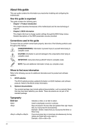
... Instructions that you MUST follow to complete a task. These documents are linked with a plus sign (+). Keys enclosed in this guide To ensure that may have been added by your... means that you must press the enclosed key. NOTE: Tips and additional information to the ASUS contact information. 2. Typography Bold text Italics ++ Indicates a menu or an item to emphasize...optional documentation, such as warranty flyers, that you need when installing and configuring the motherboard. How this guide is organized This guide contains the following sources for additional information ...
... Instructions that you MUST follow to complete a task. These documents are linked with a plus sign (+). Keys enclosed in this guide To ensure that may have been added by your... means that you must press the enclosed key. NOTE: Tips and additional information to the ASUS contact information. 2. Typography Bold text Italics ++ Indicates a menu or an item to emphasize...optional documentation, such as warranty flyers, that you need when installing and configuring the motherboard. How this guide is organized This guide contains the following sources for additional information ...
User Manual
Page 13
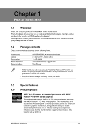
... in the long line of the items is damaged or missing, contact your motherboard package for the following items. Motherboard Cables Accessories Application DVD Documentations ASUS F1A55-M LX Series motherboard 2 x Serial ATA 3.0Gb/s cables 1 x I/O shield ASUS motherboard Support DVD User Manual • F1A55-M LX Series motherboards include F1A55-M LX PLUS and F1A55-M LX two models. series accelerated processor with AMD® Radeon™ HD 6000 series...
... in the long line of the items is damaged or missing, contact your motherboard package for the following items. Motherboard Cables Accessories Application DVD Documentations ASUS F1A55-M LX Series motherboard 2 x Serial ATA 3.0Gb/s cables 1 x I/O shield ASUS motherboard Support DVD User Manual • F1A55-M LX Series motherboards include F1A55-M LX PLUS and F1A55-M LX two models. series accelerated processor with AMD® Radeon™ HD 6000 series...
User Manual
Page 14
...Center. 100% All High-quality Conductive Polymer Capacitors (F1A55-M LX PLUS only) This motherboard uses all high-quality conductive polymer capacitors for durability, improved lifespan, and enhanced thermal capacity. 1.3.2 ASUS Exclusive Features Ai Charger Ai Charger is for experienced performance.... CrossFireX™ allows higher antialiasing, anisotropic filtering, shading, and texture settings. ASUS Anti-Surge Protection This special design protects expensive devices and the motherboard from switching power supply unit (PSU). 1-2 Chapter 1: Product introduction Users can ...
...Center. 100% All High-quality Conductive Polymer Capacitors (F1A55-M LX PLUS only) This motherboard uses all high-quality conductive polymer capacitors for durability, improved lifespan, and enhanced thermal capacity. 1.3.2 ASUS Exclusive Features Ai Charger Ai Charger is for experienced performance.... CrossFireX™ allows higher antialiasing, anisotropic filtering, shading, and texture settings. ASUS Anti-Surge Protection This special design protects expensive devices and the motherboard from switching power supply unit (PSU). 1-2 Chapter 1: Product introduction Users can ...
User Manual
Page 16
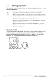
...supply and detach its power cord. The illustration below shows the location of the following precautions before you install motherboard components or change any motherboard settings. • Unplug the power cord from the wall socket before touching any component. • Before handling...component, place it on a grounded antistatic pad or in the bag that you install or remove any motherboard component. F1A55-M LX PLUS SB_PWR ON OFF Standby Power Powered Off F1A55-M LX PLUS Onboard LED 1-4 Chapter 1: Product introduction 1.4 Before you proceed Take note of the onboard LED. This ...
...supply and detach its power cord. The illustration below shows the location of the following precautions before you install motherboard components or change any motherboard settings. • Unplug the power cord from the wall socket before touching any component. • Before handling...component, place it on a grounded antistatic pad or in the bag that you install or remove any motherboard component. F1A55-M LX PLUS SB_PWR ON OFF Standby Power Powered Off F1A55-M LX PLUS Onboard LED 1-4 Chapter 1: Product introduction 1.4 Before you proceed Take note of the onboard LED. This ...
User Manual
Page 17
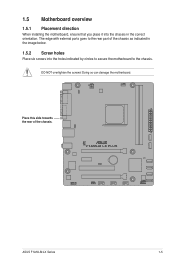
1.5 Motherboard overview 1.5.1 Placement direction When installing the motherboard, ensure that you place it into the holes indicated by circles to secure the motherboard to the rear part of the chassis. F1A55-M LX PLUS ASUS F1A55-M LX Series 1-5 The edge with external ports goes to the chassis. Place this side towards the rear of the chassis as indicated in the image below. 1.5.2 Screw holes Place six screws into the chassis in the correct orientation. DO NOT overtighten the screws! Doing so can damage the motherboard.
1.5 Motherboard overview 1.5.1 Placement direction When installing the motherboard, ensure that you place it into the holes indicated by circles to secure the motherboard to the rear part of the chassis. F1A55-M LX PLUS ASUS F1A55-M LX Series 1-5 The edge with external ports goes to the chassis. Place this side towards the rear of the chassis as indicated in the image below. 1.5.2 Screw holes Place six screws into the chassis in the correct orientation. DO NOT overtighten the screws! Doing so can damage the motherboard.
User Manual
Page 18
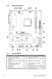
... 1-6 Chapter 1: Product introduction 1.5.3 Motherboard layout 1 2 34 54 6 21.3cm(8.4in) KB_USB56 KBPWR ATX12V EPU CPU_FAN COM1 SOCKET FM1 DDR3 DIMM_A1 (64bit, 240-pin module) DDR3 DIMM_B1 (64bit, 240-pin module) EATXPWR SATA3G_5 SATA3G_6 24.4cm(9.6in) LPT VGA 3 USB34 USBPW1-6 LAN1_USB12 AUDIO 14 RTL 8111E Super I/O CHA_FAN F1A55-M LX PLUS PCIEX16_1 PCIEX1_1 CLRTC PCI1...
... 1-6 Chapter 1: Product introduction 1.5.3 Motherboard layout 1 2 34 54 6 21.3cm(8.4in) KB_USB56 KBPWR ATX12V EPU CPU_FAN COM1 SOCKET FM1 DDR3 DIMM_A1 (64bit, 240-pin module) DDR3 DIMM_B1 (64bit, 240-pin module) EATXPWR SATA3G_5 SATA3G_6 24.4cm(9.6in) LPT VGA 3 USB34 USBPW1-6 LAN1_USB12 AUDIO 14 RTL 8111E Super I/O CHA_FAN F1A55-M LX PLUS PCIEX16_1 PCIEX1_1 CLRTC PCI1...
User Manual
Page 19
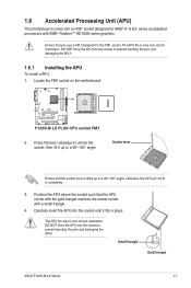
...the gold triangle matches the socket corner with a small triangle. 4. The APU fits in one correct orientation. F1A55-M LX PLUS F1A55-M LX PLUS CPU socket FM1 2. The APU fits only in only one correct orientation. DO NOT force the APU into ...& E2- otherwise, the APU will not fit in place. Locate the FM1 socket on the motherboard. 1.6 Accelerated Processing Unit (APU) This motherboard comes with AMD® Radeon™ HD 6000 series graphics. series accelerated processors with an FM1...the APU To install a APU: 1. Small triangle Gold triangle ASUS F1A55-M LX Series 1-7
...the gold triangle matches the socket corner with a small triangle. 4. The APU fits in one correct orientation. F1A55-M LX PLUS F1A55-M LX PLUS CPU socket FM1 2. The APU fits only in only one correct orientation. DO NOT force the APU into ...& E2- otherwise, the APU will not fit in place. Locate the FM1 socket on the motherboard. 1.6 Accelerated Processing Unit (APU) This motherboard comes with AMD® Radeon™ HD 6000 series graphics. series accelerated processors with an FM1...the APU To install a APU: 1. Small triangle Gold triangle ASUS F1A55-M LX Series 1-7
User Manual
Page 20
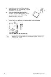
CPU_FAN F1A55-M LX PLUS F1A55-M LX PLUS CPU fan connector DO NOT forget to section 1.6.2 Installing heatsink and fan for instructions. 7. You can occur if you fail to secure the APU. When the APU is locked. 6. The lever clicks on the motherboard. Connect the CPU fan cable to the CPU_FAN connector on the side tab to indicate that...
CPU_FAN F1A55-M LX PLUS F1A55-M LX PLUS CPU fan connector DO NOT forget to section 1.6.2 Installing heatsink and fan for instructions. 7. You can occur if you fail to secure the APU. When the APU is locked. 6. The lever clicks on the motherboard. Connect the CPU fan cable to the CPU_FAN connector on the side tab to indicate that...
User Manual
Page 22
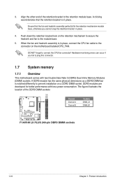
... Align the other end of the DDR3 DIMM sockets: DIMM_A1 DIMM_B1 F1A55-M LX PLUS Channel Channel A Channel B Sockets DIMM_A1 DIMM_B1 F1A55-M LX PLUS 240-pin DDR3 DIMM sockets 1-10 Chapter 1: Product introduction DDR3 ...modules are developed for better performance with two Double Data Rate 3 (DDR3) Dual Inline Memory Modules (DIMM) sockets. Hardware monitoring errors can occur if you cannot snap the retention bracket in place. 3. DO NOT forget to prevent installation on the motherboard...
... Align the other end of the DDR3 DIMM sockets: DIMM_A1 DIMM_B1 F1A55-M LX PLUS Channel Channel A Channel B Sockets DIMM_A1 DIMM_B1 F1A55-M LX PLUS 240-pin DDR3 DIMM sockets 1-10 Chapter 1: Product introduction DDR3 ...modules are developed for better performance with two Double Data Rate 3 (DDR3) Dual Inline Memory Modules (DIMM) sockets. Hardware monitoring errors can occur if you cannot snap the retention bracket in place. 3. DO NOT forget to prevent installation on the motherboard...
User Manual
Page 30
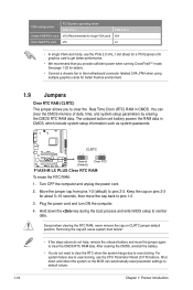
F1A55-M LX PLUS CLRTC 12 23 Normal (Default) Clear RTC F1A55-M LX PLUS Clear RTC RAM To erase the RTC RAM: 1. For system failure due to overclocking. VGA configuration Single VGA/PCIe card Dual VGA/PCIe card PCI ... card) x16 PCIe x16_2 N/A x4 • In single VGA card mode, use the CPU Parameter Recall (C.P.R) feature. You can automatically reset parameter settings to the motherboard connector labeled CHA_FAN when using multiple graphics cards for better thermal environment. 1.9 Jumpers Clear RTC RAM (CLRTC) This jumper allows you provide sufficient power when...
F1A55-M LX PLUS CLRTC 12 23 Normal (Default) Clear RTC F1A55-M LX PLUS Clear RTC RAM To erase the RTC RAM: 1. For system failure due to overclocking. VGA configuration Single VGA/PCIe card Dual VGA/PCIe card PCI ... card) x16 PCIe x16_2 N/A x4 • In single VGA card mode, use the CPU Parameter Recall (C.P.R) feature. You can automatically reset parameter settings to the motherboard connector labeled CHA_FAN when using multiple graphics cards for better thermal environment. 1.9 Jumpers Clear RTC RAM (CLRTC) This jumper allows you provide sufficient power when...
User Manual
Page 33
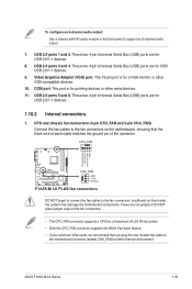
...(USB) ports are for USB 2.0/1.1 devices. 8. USB 2.0 ports 3 and 4. CPU_FAN CPU FAN PWM CPU FAN IN CPU FAN PWR GND F1A55-M LX PLUS CHA_FAN GND +12V Rotation F1A55-M LX PLUS fan connectors DO NOT forget to connect the fan cables to support an 8-channel audio output. 7. USB 2.0 ports 1 and 2. These two... labeled CHA_FAN for a VGA monitor or other serial devices. 11. Insufficient air flow inside the system may damage the motherboard components. ASUS F1A55-M LX Series 1-21 To configure an 8-channel audio output: Use a chassis with HD audio module in the front panel to the ...
...(USB) ports are for USB 2.0/1.1 devices. 8. USB 2.0 ports 3 and 4. CPU_FAN CPU FAN PWM CPU FAN IN CPU FAN PWR GND F1A55-M LX PLUS CHA_FAN GND +12V Rotation F1A55-M LX PLUS fan connectors DO NOT forget to connect the fan cables to support an 8-channel audio output. 7. USB 2.0 ports 1 and 2. These two... labeled CHA_FAN for a VGA monitor or other serial devices. 11. Insufficient air flow inside the system may damage the motherboard components. ASUS F1A55-M LX Series 1-21 To configure an 8-channel audio output: Use a chassis with HD audio module in the front panel to the ...
User Manual
Page 37
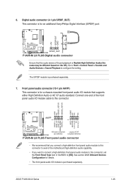
... PORT2 L F1A55-M LX PLUS HD-audio-compliant Legacy AC'97 pin definition compliant definition F1A55-M LX PLUS Front panel audio connector • We recommend that you connect a high-definition front panel audio module to this connector to avail of the motherboard high-definition audio... playback is purchased separately. 7. ASUS F1A55-M LX Series 1-25 Digital audio connector (4-1 pin SPDIF_OUT) This connector is for an additional Sony/Philips Digital Interface (S/PDIF) port. +5V SPDIFOUT GND F1A55-M LX PLUS SPDIF_OUT F1A55-M LX PLUS Digital audio connector Ensure that supports...
... PORT2 L F1A55-M LX PLUS HD-audio-compliant Legacy AC'97 pin definition compliant definition F1A55-M LX PLUS Front panel audio connector • We recommend that you connect a high-definition front panel audio module to this connector to avail of the motherboard high-definition audio... playback is purchased separately. 7. ASUS F1A55-M LX Series 1-25 Digital audio connector (4-1 pin SPDIF_OUT) This connector is for an additional Sony/Philips Digital Interface (S/PDIF) port. +5V SPDIFOUT GND F1A55-M LX PLUS SPDIF_OUT F1A55-M LX PLUS Digital audio connector Ensure that supports...
User Manual
Page 38
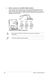
USB1112 USB910 USB78 USB+5V USB_P12USB_P12+ GND NC USB+5V USB_P10USB_P10+ GND NC USB+5V USB_P8USB_P8+ GND NC F1A55-M LX PLUS PIN 1 PIN 1 PIN 1 USB+5V USB_P11USB_P11+ GND USB+5V USB_P9USB_P9+ GND USB+5V USB_P7USB_P7+ GND F1A55-M LX PLUS USB2.0 connectors Never connect a 1394 cable to a slot opening at the back of these connectors, then install the... that supports up to 480Mbps connection speed. USB 2.0 connectors (10-1 pin USB78, USB910, USB1112) These connectors are for USB 2.0 ports. Doing so will damage the motherboard! 8.
USB1112 USB910 USB78 USB+5V USB_P12USB_P12+ GND NC USB+5V USB_P10USB_P10+ GND NC USB+5V USB_P8USB_P8+ GND NC F1A55-M LX PLUS PIN 1 PIN 1 PIN 1 USB+5V USB_P11USB_P11+ GND USB+5V USB_P9USB_P9+ GND USB+5V USB_P7USB_P7+ GND F1A55-M LX PLUS USB2.0 connectors Never connect a 1394 cable to a slot opening at the back of these connectors, then install the... that supports up to 480Mbps connection speed. USB 2.0 connectors (10-1 pin USB78, USB910, USB1112) These connectors are for USB 2.0 ports. Doing so will damage the motherboard! 8.
User Manual
Page 43
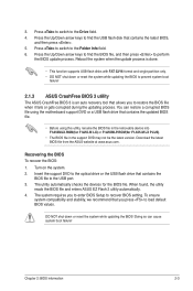
... then press . 5. The system requires you press to the USB port. 3. Turn on the system. 2. The utility automatically checks the devices for F1A55-M LX PLUS). • The BIOS file in the support DVD may not be the latest version. DO NOT shut down or reset the system while updating the... motherboard support DVD or a USB flash drive that contains the updated BIOS file. • Before using this utility, rename the BIOS file in the removable device into F1A55MLX.ROM(for F1A55-M LX) or F1A55MLP.ROM(for the BIOS file. Download the latest BIOS file from the ASUS website at www.asus.com...
... then press . 5. The system requires you press to the USB port. 3. Turn on the system. 2. The utility automatically checks the devices for F1A55-M LX PLUS). • The BIOS file in the support DVD may not be the latest version. DO NOT shut down or reset the system while updating the... motherboard support DVD or a USB flash drive that contains the updated BIOS file. • Before using this utility, rename the BIOS file in the removable device into F1A55MLX.ROM(for F1A55-M LX) or F1A55MLP.ROM(for the BIOS file. Download the latest BIOS file from the ASUS website at www.asus.com...
User Manual
Page 48
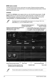
...system information, and allows you to display all fan speeds if available Displays the CPU/motherboard temperature, CPU/5V/3.3V/12V voltage output, CPU/chassis fan speed Exits the BIOS ...Refer to the Setup Mode item in the EZ Mode/Advanced Mode screen. EZ Mode Tuesday [1/1/2008] F1A55-M LX PLUS BIOS Version : 0202 CPU Type : AMD Engineering Sample Total Memory : 1024 MB (DDR3 1333MHz) ...Energy Saving Normal Use the mouse to drag or keyboard to navigate to the system. 2-8 ASUS F1A55-M LX Series The default screen for details. EZ Mode By default, the EZ Mode screen appears ...
...system information, and allows you to display all fan speeds if available Displays the CPU/motherboard temperature, CPU/5V/3.3V/12V voltage output, CPU/chassis fan speed Exits the BIOS ...Refer to the Setup Mode item in the EZ Mode/Advanced Mode screen. EZ Mode Tuesday [1/1/2008] F1A55-M LX PLUS BIOS Version : 0202 CPU Type : AMD Engineering Sample Total Memory : 1024 MB (DDR3 1333MHz) ...Energy Saving Normal Use the mouse to drag or keyboard to navigate to the system. 2-8 ASUS F1A55-M LX Series The default screen for details. EZ Mode By default, the EZ Mode screen appears ...

User Manual
Page 70
... Position : CEO Name : Jerry Shen Declaration Date: Aug. 30, 2011 Year to the following apparatus: Product name : Motherboard Model name : F1A55-M LX, F1A55-M LX PLUS conform with part 15 of the FCC Rules. No. 150, LI-TE RD., PEITOU, TAIPEI 112, TAIWAN R.O.C. Operation ...is subject to the following two conditions: (1) This device may cause undesired operation. Country: TAIWAN Authorized representative in Europe: ASUS COMPUTER ...
... Position : CEO Name : Jerry Shen Declaration Date: Aug. 30, 2011 Year to the following apparatus: Product name : Motherboard Model name : F1A55-M LX, F1A55-M LX PLUS conform with part 15 of the FCC Rules. No. 150, LI-TE RD., PEITOU, TAIPEI 112, TAIWAN R.O.C. Operation ...is subject to the following two conditions: (1) This device may cause undesired operation. Country: TAIWAN Authorized representative in Europe: ASUS COMPUTER ...


