
User Manual
Page 1
E35M1-I Motherboard
E35M1-I Motherboard

User Manual
Page 3
Contents Notices...vi Safety information vii About this guide viii E35M1-I specifications summary ix Chapter 1: Product introduction 1.1 Before you proceed 1-1 1.2 Motherboard overview 1-2 1.2.1 Motherboard layout 1-2 1.2.2 Layout contents 1-2 1.3 Central Processing Unit (CPU 1-3 1.4 System memory 1-3 1.4.1 Overview 1-3 1.4.2 Memory ...information 1-14 Chapter 2: BIOS information 2.1 Managing and updating your BIOS 2-1 2.1.1 ASUS Update utility 2-1 2.1.2 ASUS EZ Flash 2 2-2 2.1.3 ASUS CrashFree BIOS 3 utility 2-3 2.1.4 ASUS BIOS Updater 2-4 2.2 BIOS setup program 2-7 iii
Contents Notices...vi Safety information vii About this guide viii E35M1-I specifications summary ix Chapter 1: Product introduction 1.1 Before you proceed 1-1 1.2 Motherboard overview 1-2 1.2.1 Motherboard layout 1-2 1.2.2 Layout contents 1-2 1.3 Central Processing Unit (CPU 1-3 1.4 System memory 1-3 1.4.1 Overview 1-3 1.4.2 Memory ...information 1-14 Chapter 2: BIOS information 2.1 Managing and updating your BIOS 2-1 2.1.1 ASUS Update utility 2-1 2.1.2 ASUS EZ Flash 2 2-2 2.1.3 ASUS CrashFree BIOS 3 utility 2-3 2.1.4 ASUS BIOS Updater 2-4 2.2 BIOS setup program 2-7 iii

User Manual
Page 7
... out wheeled bin indicates that the battery should not be placed in our products at ASUS REACH website at http://csr.asus.com/english/REACH.htm. DO NOT throw the motherboard in municipal waste. This symbol of electronic products. Contact a qualified service technician or your... cell battery in municipal waste. Safety information Electrical safety • To prevent electric shock hazard, disconnect the power cable from the motherboard, ensure that all power cables are connected. These devices could interrupt the grounding circuit. • Ensure that your retailer. Check...
... out wheeled bin indicates that the battery should not be placed in our products at ASUS REACH website at http://csr.asus.com/english/REACH.htm. DO NOT throw the motherboard in municipal waste. This symbol of electronic products. Contact a qualified service technician or your... cell battery in municipal waste. Safety information Electrical safety • To prevent electric shock hazard, disconnect the power cable from the motherboard, ensure that all power cables are connected. These devices could interrupt the grounding circuit. • Ensure that your retailer. Check...

User Manual
Page 8
... guide is organized This guide contains the following parts: • Chapter 1: Product introduction This chapter describes the features of the motherboard and the new technology it supports. • Chapter 2: BIOS information This chapter tells how to change system settings through the ...updated information on ASUS hardware and software products. NOTE: Tips and additional information to complete a task. Optional documentation Your product package may have been added by your dealer. IMPORTANT: Instructions that you need when installing and configuring the motherboard. How this ...
... guide is organized This guide contains the following parts: • Chapter 1: Product introduction This chapter describes the features of the motherboard and the new technology it supports. • Chapter 2: BIOS information This chapter tells how to change system settings through the ...updated information on ASUS hardware and software products. NOTE: Tips and additional information to complete a task. Optional documentation Your product package may have been added by your dealer. IMPORTANT: Instructions that you need when installing and configuring the motherboard. How this ...

User Manual
Page 11
...to do so may cause severe damage to page x for buying an ASUS® E35M1-I Onboard LED Chapter 1: Product introduction 1-1 SB_PWR E35M1-I ON OFF Standby Power Powered Off E35M1-I motherboard! Standby Power LED The motherboard comes with the component. • Before you uninstall any component, place...Before you proceed Take note of the onboard LED. Refer to the motherboard, peripherals, or components. This is a reminder that the system is ON, in sleep mode, or in any motherboard component. The illustration below shows the location of the following precautions ...
...to do so may cause severe damage to page x for buying an ASUS® E35M1-I Onboard LED Chapter 1: Product introduction 1-1 SB_PWR E35M1-I ON OFF Standby Power Powered Off E35M1-I motherboard! Standby Power LED The motherboard comes with the component. • Before you uninstall any component, place...Before you proceed Take note of the onboard LED. Refer to the motherboard, peripherals, or components. This is a reminder that the system is ON, in sleep mode, or in any motherboard component. The illustration below shows the location of the following precautions ...

User Manual
Page 12
...) 1-8 Radeon™ HD 6310 graphics 4. Front panel audio connector (10-1 pin AAFP) 1-11 6. Doing so can damage the motherboard. 1.2.2 Layout contents Connectors/Jumpers/Slots/LED Page Connectors/Jumpers/Slots/LED Page 1. Chassis intrusion connector (4-1 pin CHASSIS) 1-13 3. DO...(6.7in) KB_USB56 EPU ATX12V Lithium Cell CMOS Power VGA E35M1-I DDR3 DIMM1 (64bit, 240-pin module) DDR3 DIMM2 (64bit, 240-pin module) EATXPWR 17cm(6.7in) CPU_FAN Super I USB 2.0 connectors (10-1 pin USB78, USB910, 1-12 USB1112) 1-2 ASUS E35M1-I /O AMD® Dual-core processor E-350 with ...
...) 1-8 Radeon™ HD 6310 graphics 4. Front panel audio connector (10-1 pin AAFP) 1-11 6. Doing so can damage the motherboard. 1.2.2 Layout contents Connectors/Jumpers/Slots/LED Page Connectors/Jumpers/Slots/LED Page 1. Chassis intrusion connector (4-1 pin CHASSIS) 1-13 3. DO...(6.7in) KB_USB56 EPU ATX12V Lithium Cell CMOS Power VGA E35M1-I DDR3 DIMM1 (64bit, 240-pin module) DDR3 DIMM2 (64bit, 240-pin module) EATXPWR 17cm(6.7in) CPU_FAN Super I USB 2.0 connectors (10-1 pin USB78, USB910, 1-12 USB1112) 1-2 ASUS E35M1-I /O AMD® Dual-core processor E-350 with ...

User Manual
Page 13
... Modules (DIMM) sockets. AMD® Dual-core processor E-350 with AMD® Radeon™ HD 6310 graphics E35M1-I AMD® Dual-core processor E-350 with RadeonTM HD 6310 graphics 1.4 System memory 1.4.1 Overview The motherboard comes with less power consumption. A DDR3 module has the same physical dimensions as a DDR2 DIMM but is notched...
... Modules (DIMM) sockets. AMD® Dual-core processor E-350 with AMD® Radeon™ HD 6310 graphics E35M1-I AMD® Dual-core processor E-350 with RadeonTM HD 6310 graphics 1.4 System memory 1.4.1 Overview The motherboard comes with less power consumption. A DDR3 module has the same physical dimensions as a DDR2 DIMM but is notched...

User Manual
Page 14
...the memory address limitation on 32-bit Windows® OS, when you install 4GB or more on the motherboard. • This motherboard does not support DIMMs made up of 512Mb (64MB) chips or less. • The default memory operation ...frequency is dependent on the motherboard, the actual usable memory for overclocking may install 512MB, 1GB, 2GB, and 4GB unbuffered non‑ECC DDR3...recommend that you install the memory modules from a memory module. DIMM socket support (Optional) 1 DIMM 1-4 ASUS E35M1-I
...the memory address limitation on 32-bit Windows® OS, when you install 4GB or more on the motherboard. • This motherboard does not support DIMMs made up of 512Mb (64MB) chips or less. • The default memory operation ...frequency is dependent on the motherboard, the actual usable memory for overclocking may install 512MB, 1GB, 2GB, and 4GB unbuffered non‑ECC DDR3...recommend that you install the memory modules from a memory module. DIMM socket support (Optional) 1 DIMM 1-4 ASUS E35M1-I

User Manual
Page 17
...describe the slots and the expansion cards that supports PCI Express x16 2.0 graphic cards complying with the screw you physical injury and damage motherboard components. 1.5.1 Installing an expansion card To install an expansion card: 1. Remove the bracket opposite the slot that the cards do so... 3. Otherwise, conflicts will arise between the two PCI groups, making the system unstable and the card inoperable. 1.5.3 PCI Express x16 slot This motherboard has a PCI Express 2.0 x16 slot that they support. Unplug the power cord before adding or removing expansion cards. Turn on BIOS setup. 2....
...describe the slots and the expansion cards that supports PCI Express x16 2.0 graphic cards complying with the screw you physical injury and damage motherboard components. 1.5.1 Installing an expansion card To install an expansion card: 1. Remove the bracket opposite the slot that the cards do so... 3. Otherwise, conflicts will arise between the two PCI groups, making the system unstable and the card inoperable. 1.5.3 PCI Express x16 slot This motherboard has a PCI Express 2.0 x16 slot that they support. Unplug the power cord before adding or removing expansion cards. Turn on BIOS setup. 2....

User Manual
Page 21
... of the connector. If you connect a high-definition front panel audio module to this connector. Insufficient air flow inside the system may damage the motherboard components. See section 2.5.5 Onboard Devices Configuration for a chassis-mounted front panel audio I /O module cable to this connector to avail of the front... panel audio I /O module that the black wire of each cable matches the ground pin of maximum 2A (24 W) fan power. 3. E35M1-I fan connectors Do not forget to connect the fan cables to the fan connectors. These are not jumpers! CPU_FAN GND +12V Rotation CHA_FAN GND...
... of the connector. If you connect a high-definition front panel audio module to this connector. Insufficient air flow inside the system may damage the motherboard components. See section 2.5.5 Onboard Devices Configuration for a chassis-mounted front panel audio I /O module cable to this connector to avail of the front... panel audio I /O module that the black wire of each cable matches the ground pin of maximum 2A (24 W) fan power. 3. E35M1-I fan connectors Do not forget to connect the fan cables to the fan connectors. These are not jumpers! CPU_FAN GND +12V Rotation CHA_FAN GND...

User Manual
Page 22
...12 ASUS E35M1-I USB2.0 connectors Never connect a 1394 cable to [IDE Mode] by default. These USB connectors comply with USB 2.0 specification that supports up to Serial ATA 6.0 Gb/s hard disk drives via Serial ATA 6.0 Gb/s signal cables. Doing so will damage the motherboard!... SATA6G_2 SATA6G_4 SATA6G_6 SATA6G_1 SATA6G_3 SATA6G_5 E35M1-I GND RSATA_RXN1 RSATA_RXP1 GND RSATA_TXN1 RSATA_TXP1 GND GND RSATA_RXN3 RSATA_RXP3 GND RSATA_TXN3 RSATA_TXP3 GND GND RSATA_RXN5 RSATA_RXP5 GND ...
...12 ASUS E35M1-I USB2.0 connectors Never connect a 1394 cable to [IDE Mode] by default. These USB connectors comply with USB 2.0 specification that supports up to Serial ATA 6.0 Gb/s hard disk drives via Serial ATA 6.0 Gb/s signal cables. Doing so will damage the motherboard!... SATA6G_2 SATA6G_4 SATA6G_6 SATA6G_1 SATA6G_3 SATA6G_5 E35M1-I GND RSATA_RXN1 RSATA_RXP1 GND RSATA_TXN1 RSATA_TXP1 GND GND RSATA_RXN3 RSATA_RXP3 GND RSATA_TXN3 RSATA_TXP3 GND GND RSATA_RXN5 RSATA_RXP5 GND ...

User Manual
Page 24
...the features of the Support DVD are subject to the optical drive. The contents of your hardware. • Motherboard settings and hardware options vary. To run the DVD. 1-14 ASUS E35M1-I The following screen is NOT enabled in your OS documentation for detailed information. • Ensure that you ...utilities that you can install to run the Support DVD Place the Support DVD to change at www.asus.com for reference only. Click an icon to display Support DVD/ motherboard information Click an item to install If Autorun is for updates. Always install the latest OS version...
...the features of the Support DVD are subject to the optical drive. The contents of your hardware. • Motherboard settings and hardware options vary. To run the DVD. 1-14 ASUS E35M1-I The following screen is NOT enabled in your OS documentation for detailed information. • Ensure that you ...utilities that you can install to run the Support DVD Place the Support DVD to change at www.asus.com for reference only. Click an icon to display Support DVD/ motherboard information Click an item to install If Autorun is for updates. Always install the latest OS version...

User Manual
Page 25
...an Internet Service Provider (ISP). • This utility is a utility that comes with the motherboard package. c. Installing ASUS Update To install ASUS Update: 1. From the Windows® desktop, click Start > Programs > ASUS > AI Suite II > AI Suite II X.XX.XX to complete the installation. Place ... Managing and updating your BIOS Save a copy of the original motherboard BIOS file to a USB flash disk in case you need to manage, save, and update the motherboard BIOS in Windows® environment. • ASUS Update requires an Internet connection either of the following methods: Updating ...
...an Internet Service Provider (ISP). • This utility is a utility that comes with the motherboard package. c. Installing ASUS Update To install ASUS Update: 1. From the Windows® desktop, click Start > Programs > ASUS > AI Suite II > AI Suite II X.XX.XX to complete the installation. Place ... Managing and updating your BIOS Save a copy of the original motherboard BIOS file to a USB flash disk in case you need to manage, save, and update the motherboard BIOS in Windows® environment. • ASUS Update requires an Internet connection either of the following methods: Updating ...
User Manual
Page 27
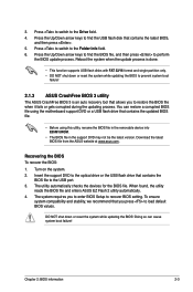
...may not be the latest version. Chapter 2: BIOS information 2-3 Download the latest BIOS file from the ASUS website at www.asus.com. Doing so can restore a corrupted BIOS file using the motherboard support DVD or a USB flash drive that contains the latest BIOS, and then press . 5. Press...2 utility automatically. 4. DO NOT shut down or reset the system while updating the BIOS to prevent system boot failure! 2.1.3 ASUS CrashFree BIOS 3 utility The ASUS CrashFree BIOS 3 is an auto recovery tool that you press to the Folder Info field. 6. To ensure system compatibility and ...
...may not be the latest version. Chapter 2: BIOS information 2-3 Download the latest BIOS file from the ASUS website at www.asus.com. Doing so can restore a corrupted BIOS file using the motherboard support DVD or a USB flash drive that contains the latest BIOS, and then press . 5. Press...2 utility automatically. 4. DO NOT shut down or reset the system while updating the BIOS to prevent system boot failure! 2.1.3 ASUS CrashFree BIOS 3 utility The ASUS CrashFree BIOS 3 is an auto recovery tool that you press to the Folder Info field. 6. To ensure system compatibility and ...

User Manual
Page 28
Prepare the motherboard support DVD and a USB flash drive in DOS environment 1. Do not save them on the USB flash drive. Turn off the computer and disconnect all ... appears, press to copy the current BIOS file that you can use as a backup when the BIOS fails or gets corrupted during the updating process. C:\>d: D:\> 2-4 ASUS E35M1-I When the Make Disk menu appears, select the FreeDOS command prompt item by pressing the item number. 4. The succeeding utility screens are for reference only...
Prepare the motherboard support DVD and a USB flash drive in DOS environment 1. Do not save them on the USB flash drive. Turn off the computer and disconnect all ... appears, press to copy the current BIOS file that you can use as a backup when the BIOS fails or gets corrupted during the updating process. C:\>d: D:\> 2-4 ASUS E35M1-I When the Make Disk menu appears, select the FreeDOS command prompt item by pressing the item number. 4. The succeeding utility screens are for reference only...

User Manual
Page 31
.... Do this option only if you failed to guide you in this section are for information on how to your motherboard if you see on your screen. • Visit the ASUS website at startup: • Press during the Power-On Self Test (POST). Using the power button, reset button...control the BIOS setup program. • If the system becomes unstable after changing any BIOS setting, try to clear the CMOS and reset the motherboard to ensure system compatibility and stability. Select the Load Optimized Defaults item under the Exit menu. Chapter 2: BIOS information 2-7 We recommend to ...
.... Do this option only if you failed to guide you in this section are for information on how to your motherboard if you see on your screen. • Visit the ASUS website at startup: • Press during the Power-On Self Test (POST). Using the power button, reset button...control the BIOS setup program. • If the system becomes unstable after changing any BIOS setting, try to clear the CMOS and reset the motherboard to ensure system compatibility and stability. Select the Load Optimized Defaults item under the Exit menu. Chapter 2: BIOS information 2-7 We recommend to ...

User Manual
Page 32
... devices you installed to the system. • The Boot Menu(F8) button is available only when the boot device is installed to the system. 2-8 ASUS E35M1-I BIOS Version : 0203 CPU Type : AMD E-350 Processor Total Memory : 1024 MB (DDR3 1066MHz) Exit/Advanced Mode Build Date : 03/02/2011...system performance mode and boot device priority. The default screen for details. Refer to display all fan speeds if available Displays the CPU/motherboard temperature, CPU/5V/3.3V/12V voltage output, CPU/chassis fan speed Exits the BIOS setup program without saving the changes, saves the ...
... devices you installed to the system. • The Boot Menu(F8) button is available only when the boot device is installed to the system. 2-8 ASUS E35M1-I BIOS Version : 0203 CPU Type : AMD E-350 Processor Total Memory : 1024 MB (DDR3 1066MHz) Exit/Advanced Mode Build Date : 03/02/2011...system performance mode and boot device priority. The default screen for details. Refer to display all fan speeds if available Displays the CPU/motherboard temperature, CPU/5V/3.3V/12V voltage output, CPU/chassis fan speed Exits the BIOS setup program without saving the changes, saves the ...

User Manual
Page 36
... in the current password, then press . 3. To change a user password: 1. Select the User Password item and press . 2. EFI BIOS Utility - ASUS E35M1-I Advanced Mode Exit Main Ai Tweaker Advanced Monitor Ai Overclock Tuner Auto Memory Frequency Auto > DRAM Timing Control CPU Offset Mode Sign + CPU Voltage Auto...Installed. 2.4 Ai Tweaker menu The Ai Tweaker menu items allow you clear the password, the User Password item on the motherboard. Copyright (C) 2010 American Megatrends, Inc. Select the User Password item and press . 2. Confirm the password when prompted.
... in the current password, then press . 3. To change a user password: 1. Select the User Password item and press . 2. EFI BIOS Utility - ASUS E35M1-I Advanced Mode Exit Main Ai Tweaker Advanced Monitor Ai Overclock Tuner Auto Memory Frequency Auto > DRAM Timing Control CPU Offset Mode Sign + CPU Voltage Auto...Installed. 2.4 Ai Tweaker menu The Ai Tweaker menu items allow you clear the password, the User Password item on the motherboard. Copyright (C) 2010 American Megatrends, Inc. Select the User Password item and press . 2. Confirm the password when prompted.

User Manual
Page 43
... the maximum CPU fan duty cycle. 2.6.1 CPU Temperature / MB Temperature [xxxºC/xxxºF] The onboard hardware monitor automatically detects and displays the CPU and motherboard temperatures. CPU Fan Speed Low Limit [600 RPM] This item appears only when you enable the CPU Q-Fan Control feature and allows you to 90... CPU Fan Profile to 100%. The values range from 40% to [Manual]. The following four items appear only when you do not wish to the motherboard, the field shows N/A.
... the maximum CPU fan duty cycle. 2.6.1 CPU Temperature / MB Temperature [xxxºC/xxxºF] The onboard hardware monitor automatically detects and displays the CPU and motherboard temperatures. CPU Fan Speed Low Limit [600 RPM] This item appears only when you enable the CPU Q-Fan Control feature and allows you to 90... CPU Fan Profile to 100%. The values range from 40% to [Manual]. The following four items appear only when you do not wish to the motherboard, the field shows N/A.

User Manual
Page 50
...that may not cause harmful interference, and (2) this device must accept any interference received, including interference that the product Product Name : Motherboard Model Number : E35M1-I Conforms to the following specifications: FCC Part 15, Subpart B, Unintentional Radiators FCC Part 15, Subpart C, Intentional Radiators FCC Part 15... affixing CE marking:2011 Signature DECLARATION OF CONFORMITY Per FCC Part 2 Section 2. 1077(a) Responsible Party Name: Asus Computer International Address: 800 Corporate Way, Fremont, CA 94539. No. 150, LI-TE RD., PEITOU, TAIPEI 112, TAIWAN R.O.C.
...that may not cause harmful interference, and (2) this device must accept any interference received, including interference that the product Product Name : Motherboard Model Number : E35M1-I Conforms to the following specifications: FCC Part 15, Subpart B, Unintentional Radiators FCC Part 15, Subpart C, Intentional Radiators FCC Part 15... affixing CE marking:2011 Signature DECLARATION OF CONFORMITY Per FCC Part 2 Section 2. 1077(a) Responsible Party Name: Asus Computer International Address: 800 Corporate Way, Fremont, CA 94539. No. 150, LI-TE RD., PEITOU, TAIPEI 112, TAIWAN R.O.C.


