
P4S333-VM User Manual
Page 7
... the power supply is set to fix it , carefully read all the manuals that the power cables for the devices are unplugged before you are not damaged. These devices could interrupt the grounding circuit. • Make sure that your power supply is broken, do not try to the correct voltage in any damage, contact your retailer. Operation safety • Before installing the motherboard and adding devices...
... the power supply is set to fix it , carefully read all the manuals that the power cables for the devices are unplugged before you are not damaged. These devices could interrupt the grounding circuit. • Make sure that your power supply is broken, do not try to the correct voltage in any damage, contact your retailer. Operation safety • Before installing the motherboard and adding devices...
P4S333-VM User Manual
Page 13
... start installing the motherboard, and hardware devices on it another standout in the long line of system memory with PC2100/1600 DDR SDRAM, high-resolution graphics via an AGP 4X slot, USB capability, communication and networking options, high-speed data transfers using the ATA100 protocol, and AC '97-compliant audio features, the P4S333VM is damaged or missing, contact your retailer. Supporting up to 2GB of ASUS...
... start installing the motherboard, and hardware devices on it another standout in the long line of system memory with PC2100/1600 DDR SDRAM, high-resolution graphics via an AGP 4X slot, USB capability, communication and networking options, high-speed data transfers using the ATA100 protocol, and AC '97-compliant audio features, the P4S333VM is damaged or missing, contact your retailer. Supporting up to 2GB of ASUS...

P4S333-VM User Manual
Page 18
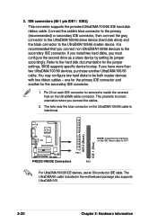
... the floppy disk cable. 11 Flash EEPROM. This chip performs multiple system functions that include hardware and system voltage monitoring. 9 Onboard LED This green indicator light informs the user that power is slotted to four Ultra DMA/100/66, PIO Modes 3 & 4 IDE devices. This Low Pin Count (LPC) interface provides the commonly used Super I /O controller. This power connector connects the 4-pin 12V plug from the ATX 12V power supply. 2 CPU socket. A 478-pin surface...
... the floppy disk cable. 11 Flash EEPROM. This chip performs multiple system functions that include hardware and system voltage monitoring. 9 Onboard LED This green indicator light informs the user that power is slotted to four Ultra DMA/100/66, PIO Modes 3 & 4 IDE devices. This Low Pin Count (LPC) interface provides the commonly used Super I /O controller. This power connector connects the 4-pin 12V plug from the ATX 12V power supply. 2 CPU socket. A 478-pin surface...

P4S333-VM User Manual
Page 19
... motherboard user guide 1-7 This ICS 1893Y LAN PHY works with a PCI audio accelerator or core logic that supports the AC '97 interface, the CODEC delivers a cost-effective, superior quality audio solution. (on audio models only) 15 AGP slot. This Mic (pink) jack connects a microphone. (on LAN models only) 17 PS/2 mouse port. This 15-pin VGA port supports all types of visual displays, including CRTs and VGA monitors. 25 Serial port. This purple 6-pin connector is for two additional USB ports...
... motherboard user guide 1-7 This ICS 1893Y LAN PHY works with a PCI audio accelerator or core logic that supports the AC '97 interface, the CODEC delivers a cost-effective, superior quality audio solution. (on audio models only) 15 AGP slot. This Mic (pink) jack connects a microphone. (on LAN models only) 17 PS/2 mouse port. This 15-pin VGA port supports all types of visual displays, including CRTs and VGA monitors. 25 Serial port. This purple 6-pin connector is for two additional USB ports...
P4S333-VM User Manual
Page 37
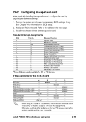
... card, configure the card by adjusting the software settings. 1. shared shared shared - - - - Otherwise, conflicts will arise between the two PCI groups, making the system unstable and the card inoperable. shared shared - ASUS P4S333-VM motherboard user guide 2-15 Install the software drivers for this motherboard PCI slot 1 PCI slot 2 PCI slot 3 Onboard USB controller HC0 Onboard USB controller HC1 AGP Onboard audio Onboard LAN Onboard VGA A - - - - - shared - - - - D - - See Chapter 4 for ISA or PCI devices. Turn on shared slots, ensure that the drivers support...
... card, configure the card by adjusting the software settings. 1. shared shared shared - - - - Otherwise, conflicts will arise between the two PCI groups, making the system unstable and the card inoperable. shared shared - ASUS P4S333-VM motherboard user guide 2-15 Install the software drivers for this motherboard PCI slot 1 PCI slot 2 PCI slot 3 Onboard USB controller HC0 Onboard USB controller HC1 AGP Onboard audio Onboard LAN Onboard VGA A - - - - - shared - - - - D - - See Chapter 4 for ISA or PCI devices. Turn on shared slots, ensure that the drivers support...

P4S333-VM User Manual
Page 41
... the power connector on hard drives and CD-ROM drives, but may be on the opposite side on the connectors. Hard disk activity LED (2-pin IDELED) This connector supplies power to your motherboard. IDELED P4S333-VM IDE Activity LED ASUS P4S333-VM motherboard user guide 2-19 Some pins are clearly distinguished from jumpers in the Motherboard Layout. Placing jumper caps over these connector pins will cause damage to the hard disk activity LED. Always connect ribbon cables with the red stripe to light up...
... the power connector on hard drives and CD-ROM drives, but may be on the opposite side on the connectors. Hard disk activity LED (2-pin IDELED) This connector supplies power to your motherboard. IDELED P4S333-VM IDE Activity LED ASUS P4S333-VM motherboard user guide 2-19 Some pins are clearly distinguished from jumpers in the Motherboard Layout. Placing jumper caps over these connector pins will cause damage to the hard disk activity LED. Always connect ribbon cables with the red stripe to light up...
P4S333-VM User Manual
Page 42
... IDE connector. If you install two hard disks, you have more than two UltraDMA/100/66 devices, purchase another for the jumper settings. BIOS supports specific device bootup. one for the primary IDE connector and another UltraDMA/100/66 cable. The UltraDMA/66 cable included in the motherboard package also supports UltraDMA/100. 2-20 Chapter 2: Hardware information If you must configure the second drive as a slave device by setting its jumper accordingly. Pin...
... IDE connector. If you install two hard disks, you have more than two UltraDMA/100/66 devices, purchase another for the jumper settings. BIOS supports specific device bootup. one for the primary IDE connector and another UltraDMA/100/66 cable. The UltraDMA/66 cable included in the motherboard package also supports UltraDMA/100. 2-20 Chapter 2: Hardware information If you must configure the second drive as a slave device by setting its jumper accordingly. Pin...

P4S333-VM User Manual
Page 43
... motherboard, connect the other end to the floppy drive. (Pin 5 is removed to PIN 1. ® PIN 1 P4S333-VM Floppy Disk Drive Connector 4. The fan wiring and plug may damage the motherboard components. DO NOT place jumper caps on the fan manufacturer. Floppy disk drive connector (34-1 pin FLOPPY) This connector supports the provided floppy drive ribbon cable. P4S333-VM NOTE: Orient the red markings on the floppy ribbon cable to prevent incorrect insertion when using ribbon cables...
... motherboard, connect the other end to the floppy drive. (Pin 5 is removed to PIN 1. ® PIN 1 P4S333-VM Floppy Disk Drive Connector 4. The fan wiring and plug may damage the motherboard components. DO NOT place jumper caps on the fan manufacturer. Floppy disk drive connector (34-1 pin FLOPPY) This connector supports the provided floppy drive ribbon cable. P4S333-VM NOTE: Orient the red markings on the floppy ribbon cable to prevent incorrect insertion when using ribbon cables...

P4S333-VM User Manual
Page 49
Pressing the power switch turns the system between ON and SLEEP, or ON and SOFT OFF, depending on the BIOS or OS settings. ASUS P4S333-VM motherboard user guide 2-27 Pressing the power switch while in the ON mode for more than 4 seconds turns the system OFF. • Reset Switch Lead (2-pin RESET) This 2-pin connector connects to the case-mounted reset switch for rebooting the system without turning off the system power. • ATX Power Switch / Soft-Off Switch Lead (2-pin PWR) This connector connects a switch that controls the system power.
Pressing the power switch turns the system between ON and SLEEP, or ON and SOFT OFF, depending on the BIOS or OS settings. ASUS P4S333-VM motherboard user guide 2-27 Pressing the power switch while in the ON mode for more than 4 seconds turns the system OFF. • Reset Switch Lead (2-pin RESET) This 2-pin connector connects to the case-mounted reset switch for rebooting the system without turning off the system power. • ATX Power Switch / Soft-Off Switch Lead (2-pin PWR) This connector connects a switch that controls the system power.

P4S333-VM User Manual
Page 53
... a power outlet that all the connections, replace the system case cover. 2. Check the jumper settings and connections or call your monitor complies with the last device on the screen. Follow the instructions in the following order: a. 3.1 Starting up for assistance. Be sure that is working Meaning No error during POST No DRAM installed or detected Video card not found or video card memory bad CPU overheated; Turn on the system front panel case lights up or switch...
... a power outlet that all the connections, replace the system case cover. 2. Check the jumper settings and connections or call your monitor complies with the last device on the screen. Follow the instructions in the following order: a. 3.1 Starting up for assistance. Be sure that is working Meaning No error during POST No DRAM installed or detected Video card not found or video card memory bad CPU overheated; Turn on the system front panel case lights up or switch...

P4S333-VM User Manual
Page 57
... file works only in DOS mode. It is recommended that you reboot using a floppy disk. 3. BIOS setup must specify "Floppy" as the first item in case you need to the programmable flash ROM on the upper left-hand corner of your screen during bootup. AFLASH.EXE is a Flash Memory Writer utility that updates the BIOS by the Flash Memory Writer utility. Type COPY D:\AFLASH\AFLASH.EXE A:\ (assuming D is your CD-ROM drive) to...
... file works only in DOS mode. It is recommended that you reboot using a floppy disk. 3. BIOS setup must specify "Floppy" as the first item in case you need to the programmable flash ROM on the upper left-hand corner of your screen during bootup. AFLASH.EXE is a Flash Memory Writer utility that updates the BIOS by the Flash Memory Writer utility. Type COPY D:\AFLASH\AFLASH.EXE A:\ (assuming D is your CD-ROM drive) to...
P4S333-VM User Manual
Page 61
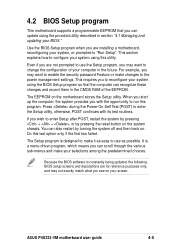
... update using this utility. Because the BIOS software is a menu-driven program, which means you see on . Press during the Power-On Self Test (POST) to configure your system using the provided utility described in the CMOS RAM of your computer in the future. ASUS P4S333-VM motherboard user guide 4-5 4.2 BIOS Setup program This motherboard supports a programmable EEPROM that the computer can recognize these changes and record them in section "4.1 Managing and updating your BIOS...
... update using this utility. Because the BIOS software is a menu-driven program, which means you see on . Press during the Power-On Self Test (POST) to configure your system using the provided utility described in the CMOS RAM of your computer in the future. ASUS P4S333-VM motherboard user guide 4-5 4.2 BIOS Setup program This motherboard supports a programmable EEPROM that the computer can recognize these changes and record them in section "4.1 Managing and updating your BIOS...
P4S333-VM User Manual
Page 67
... Method field to [Manual]. To make changes to this field. CHS Capacity This field shows the drive's maximum CHS capacity as calculated by the BIOS based on the drive information you entered. Configuration options: [Disabled] [2 Sectors] [4 Sectors] [8 Sectors] [16 Sectors] [32 Sectors] [Maximum] ASUS P4S333-VM motherboard user guide 4-11 Configuration options: [LBA] [LARGE] [Normal] [Match Partition Table] [Manual] Cylinders This field configures the number of the hard drive is enabled, the 28...
... Method field to [Manual]. To make changes to this field. CHS Capacity This field shows the drive's maximum CHS capacity as calculated by the BIOS based on the drive information you entered. Configuration options: [Disabled] [2 Sectors] [4 Sectors] [8 Sectors] [16 Sectors] [32 Sectors] [Maximum] ASUS P4S333-VM motherboard user guide 4-11 Configuration options: [LBA] [LARGE] [Normal] [Match Partition Table] [Manual] Cylinders This field configures the number of the hard drive is enabled, the 28...
P4S333-VM User Manual
Page 93
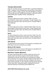
.... If Autorun is enabled in the support CD to your CD-ROM drive. Refer to display the menu. The contents of your screen. ASUS P4S333-VM motherboard user guide 5-1 Visit the ASUS website for updates. 5.2.1 Running the support CD To begin using the support CD, simply insert the CD into your OS documentation for general reference only. If the installation menu did not appear automatically, locate and doubleclick on the...
.... If Autorun is enabled in the support CD to your CD-ROM drive. Refer to display the menu. The contents of your screen. ASUS P4S333-VM motherboard user guide 5-1 Visit the ASUS website for updates. 5.2.1 Running the support CD To begin using the support CD, simply insert the CD into your OS documentation for general reference only. If the installation menu did not appear automatically, locate and doubleclick on the...

P4S333-VM User Manual
Page 101
... support next-generation auto-intensive PC applications such as VCRs, TVs, phones, and stereos. For example, inserting a tape into a VCR can turn ON and OFF peripherals such as CD-ROMs, network cards, hard disk drives, and printers, as well as consumer devices connected to the PC such as DVD, 3-D multiplayer gaming and interactive music. ASUS P4S333-VM motherboard user guide G-1 This specification uses software emulation to compete with audio...
... support next-generation auto-intensive PC applications such as VCRs, TVs, phones, and stereos. For example, inserting a tape into a VCR can turn ON and OFF peripherals such as CD-ROMs, network cards, hard disk drives, and printers, as well as consumer devices connected to the PC such as DVD, 3-D multiplayer gaming and interactive music. ASUS P4S333-VM motherboard user guide G-1 This specification uses software emulation to compete with audio...
P4S333-VM User Manual
Page 102
... your computer. G-2 Appendix C: Glossary "Reboot" means to use a different IRQ and address assignment. When using the AFLASH utility by the computer. Bus master IDE driver and bus master IDE hard disk drives are required to represent a single alphanumeric character, punctuation mark, or other symbol. A type of RAM that the CPU be involved in the cache memory. A software component that supports serial devices such as printers, mice...
... your computer. G-2 Appendix C: Glossary "Reboot" means to use a different IRQ and address assignment. When using the AFLASH utility by the computer. Bus master IDE driver and bus master IDE hard disk drives are required to represent a single alphanumeric character, punctuation mark, or other symbol. A type of RAM that the CPU be involved in the cache memory. A software component that supports serial devices such as printers, mice...

P4S333-VM User Manual
Page 103
... the monitor screen. A printed circuit card suchas an audio card, a video card, or a LAN card that requires refresh cycles to the operating system. Internet. The specific memory location for the OS. Two devices cannot share the same I /O (Input/Output). Flash ROM. IDE devices integrate the drive control circuitry directly on the motherboard. I /O address space. Device Driver. The driver translates these commands into an expansion slot on the drive itself, eliminating the need for SCSI devices). ASUS P4S333-VM motherboard user guide G-3 Each device...
... the monitor screen. A printed circuit card suchas an audio card, a video card, or a LAN card that requires refresh cycles to the operating system. Internet. The specific memory location for the OS. Two devices cannot share the same I /O (Input/Output). Flash ROM. IDE devices integrate the drive control circuitry directly on the motherboard. I /O address space. Device Driver. The driver translates these commands into an expansion slot on the drive itself, eliminating the need for SCSI devices). ASUS P4S333-VM motherboard user guide G-3 Each device...

P4S333-VM User Manual
Page 104
... CPU can connect to the ISP using a modem installed in the computer and connected to the Internet and the World Wide Web for memory capacity as one of linked computers are separated by expansion card manufacturers. The IrDA protocol is a specification that controls the overall operation of others. Network. The software that defines a 32-bit data bus interface. The ISP also provides Internet utilities and services...
... CPU can connect to the ISP using a modem installed in the computer and connected to the Internet and the World Wide Web for memory capacity as one of linked computers are separated by expansion card manufacturers. The IrDA protocol is a specification that controls the overall operation of others. Network. The software that defines a 32-bit data bus interface. The ISP also provides Internet utilities and services...

P4S333-VM User Manual
Page 105
... processing. SDRAM takes memory access away from the CPU control; SIR (Serial IrDA). ASUS P4S333-VM motherboard user guide G-5 The POST checks system memory, the motherboard circuitry, the display, the keyboard, the diskette drive, and other storage media like an ID detect for SDRAM module, it will first run through the POST, a series of architecture transfers data through a 16-bit or 32-bit bus. RAM (Random Access Memory). The information...
... processing. SDRAM takes memory access away from the CPU control; SIR (Serial IrDA). ASUS P4S333-VM motherboard user guide G-5 The POST checks system memory, the motherboard circuitry, the display, the keyboard, the diskette drive, and other storage media like an ID detect for SDRAM module, it will first run through the POST, a series of architecture transfers data through a 16-bit or 32-bit bus. RAM (Random Access Memory). The information...

P4S333-VM User Manual
Page 109
... 4-33 Setup Program 4-5 Sub-menu launching 4-7 Updating 4-1 BIOS Beep Codes 3-1 BIOS Flash Utility 5-3 Boot Device selection 4-30 Boot Up NumLock Status 4-13 Boot Virus Detection 4-31 C Card Reader support 1-2 Central Processing Unit (CPU) fan connector 2-21 installation 2-5 Central Processing Unit (CPU) Level 1/Level 2 Cache 4-16 Speed 4-15 CPU socket 1-6 Chip Configuration 4-17 Clear RTC RAM 2-18 Connectors ATX 12V 1-6 ATX power 1-6 chassis alarm 2-21 digital audio 2-24 fan 2-21 floppy disk 1-6, 2-21 HDD LED 2-19 IDE 1-6 infrared module 2-25 internal audio 2-23 panel 2-26 power supply 2-22...
... 4-33 Setup Program 4-5 Sub-menu launching 4-7 Updating 4-1 BIOS Beep Codes 3-1 BIOS Flash Utility 5-3 Boot Device selection 4-30 Boot Up NumLock Status 4-13 Boot Virus Detection 4-31 C Card Reader support 1-2 Central Processing Unit (CPU) fan connector 2-21 installation 2-5 Central Processing Unit (CPU) Level 1/Level 2 Cache 4-16 Speed 4-15 CPU socket 1-6 Chip Configuration 4-17 Clear RTC RAM 2-18 Connectors ATX 12V 1-6 ATX power 1-6 chassis alarm 2-21 digital audio 2-24 fan 2-21 floppy disk 1-6, 2-21 HDD LED 2-19 IDE 1-6 infrared module 2-25 internal audio 2-23 panel 2-26 power supply 2-22...


