

Motherboard DIY Troubleshooting Guide
Page 13
...® Pentium® 4 Processor in the world of power computing! Supporting up to set a new benchmark for an effective desktop platform solution. Before you for a 3.5-inch floppy drive Bag of extra jumper caps User Guide If any of system memory with PC100/133 unbuffered SDRAM, high-resolution graphics via an AGP 4X slot, communication and networking options through a CNR slot, high-speed data transfers using the ATA100 protocol...
...® Pentium® 4 Processor in the world of power computing! Supporting up to set a new benchmark for an effective desktop platform solution. Before you for a 3.5-inch floppy drive Bag of extra jumper caps User Guide If any of system memory with PC100/133 unbuffered SDRAM, high-resolution graphics via an AGP 4X slot, communication and networking options through a CNR slot, high-speed data transfers using the ATA100 protocol...
Motherboard DIY Troubleshooting Guide
Page 15
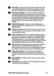
... of the floppy disk cable. 8 Flash EEPROM. The MCH provides the processor interface, system memory interface, AGP interface, and Hub Interface. 3 SDRAM DIMM sockets. This 2Mb firmware contains the programmable BIOS program. 9 DIP switches. ASUS P4B-M motherboard user guide 1-3 This socket accommodates the Intel® Pentium® 4 478/Northwood Processor with the south bridge Intel I/O Controller Hub 2 (ICH2) are slotted to 3GB using unbuffered ECC or...
... of the floppy disk cable. 8 Flash EEPROM. The MCH provides the processor interface, system memory interface, AGP interface, and Hub Interface. 3 SDRAM DIMM sockets. This 2Mb firmware contains the programmable BIOS program. 9 DIP switches. ASUS P4B-M motherboard user guide 1-3 This socket accommodates the Intel® Pentium® 4 478/Northwood Processor with the south bridge Intel I/O Controller Hub 2 (ICH2) are slotted to 3GB using unbuffered ECC or...

Motherboard DIY Troubleshooting Guide
Page 16
...-bit PCI 2.2 expansion slots support bus master PCI cards like SCSI or LAN cards with 133MB/s maximum throughput. 16 AGP slot. 10 South bridge controller. Referred to turn off the system power before plugging or unplugging devices. 13 CNR slot. This Line Out (lime) jack connects a headphone or a speaker. 21 Game/MIDI connector. This slot is a standby power on the motherboard. This chip performs multiple system functions that allows access to...
...-bit PCI 2.2 expansion slots support bus master PCI cards like SCSI or LAN cards with 133MB/s maximum throughput. 16 AGP slot. 10 South bridge controller. Referred to turn off the system power before plugging or unplugging devices. 13 CNR slot. This Line Out (lime) jack connects a headphone or a speaker. 21 Game/MIDI connector. This slot is a standby power on the motherboard. This chip performs multiple system functions that allows access to...

Motherboard DIY Troubleshooting Guide
Page 17
... installed. You do not have to a Local Area Network (LAN) through a network hub. 27 PS/2 keyboard port. This green 6-pin connector is for connecting USB devices such as a mouse and PDA. 26 RJ-45 port. This power connector connects the 4-pin 12V plug from the ATX 12V power supply. 23 Serial ports. These two 9-pin COM1/COM2 ports are available for a PS/2 keyboard. 28 PS/2 mouse port. Retention Module Base Figure 1-2 Pre-installed Heatsink Retention Module Base ASUS P4B-M motherboard user guide...
... installed. You do not have to a Local Area Network (LAN) through a network hub. 27 PS/2 keyboard port. This green 6-pin connector is for connecting USB devices such as a mouse and PDA. 26 RJ-45 port. This power connector connects the 4-pin 12V plug from the ATX 12V power supply. 23 Serial ports. These two 9-pin COM1/COM2 ports are available for a PS/2 keyboard. 28 PS/2 mouse port. Retention Module Base Figure 1-2 Pre-installed Heatsink Retention Module Base ASUS P4B-M motherboard user guide...

Motherboard DIY Troubleshooting Guide
Page 34
... 4 ACPI Mode when used - - - - PCI slot 2 - - - - - - Onboard LAN - - - - shared - - shared - - - When using PCI cards on the system and change the necessary BIOS settings, if any. IRQ assignments for the expansion card. Onboard USB controller HC1 shared AGP used - shared - - Turn on shared slots, ensure that the drivers support "Share IRQ" or that the cards do not need IRQ assignments. used CNR LAN - - - - used - - - - - - Install the software drivers for this motherboard A B C D E F G H PCI slot 1 - - - - - See Chapter 4 for ISA or PCI devices...
... 4 ACPI Mode when used - - - - PCI slot 2 - - - - - - Onboard LAN - - - - shared - - shared - - - When using PCI cards on the system and change the necessary BIOS settings, if any. IRQ assignments for the expansion card. Onboard USB controller HC1 shared AGP used - shared - - Turn on shared slots, ensure that the drivers support "Share IRQ" or that the cards do not need IRQ assignments. used CNR LAN - - - - used - - - - - - Install the software drivers for this motherboard A B C D E F G H PCI slot 1 - - - - - See Chapter 4 for ISA or PCI devices...

Motherboard DIY Troubleshooting Guide
Page 39
...the +5VSB lead, and a corresponding setting in the BIOS (see section 4.5.1 Power Up Control). P4B-M KBPWR 2 1 +5V (Default) 3 2 +5VSB ® P4B-M Keyboard Power Setting Figure 2-25 Keyboard Power Settings ASUS P4B-M motherboard user guide 2-19 USB port selection (3-pin CNRUSB0, CNRUSB1) When set to activate USB port 3. Both jumpers are set to pins 2-3 activates the CNR slot. 2. CNRUSB0 CNRUSB1 P4B-M ® P4B-M USB/CNR Selection 12 Use External USB Ports (Default) Figure 2-24 USB Port Selection 23 Use CNR USB 3. Setting the jumpers to pins 1-2, these jumpers.
...the +5VSB lead, and a corresponding setting in the BIOS (see section 4.5.1 Power Up Control). P4B-M KBPWR 2 1 +5V (Default) 3 2 +5VSB ® P4B-M Keyboard Power Setting Figure 2-25 Keyboard Power Settings ASUS P4B-M motherboard user guide 2-19 USB port selection (3-pin CNRUSB0, CNRUSB1) When set to activate USB port 3. Both jumpers are set to pins 2-3 activates the CNR slot. 2. CNRUSB0 CNRUSB1 P4B-M ® P4B-M USB/CNR Selection 12 Use External USB Ports (Default) Figure 2-24 USB Port Selection 23 Use CNR USB 3. Setting the jumpers to pins 1-2, these jumpers.

Motherboard DIY Troubleshooting Guide
Page 40
... switch the jumpers from the default position Center/Bass (pins 2-3) to Bass/Center (pins 1-2) to reroute signals on LAN models only) This jumper allows you to install the multichannel audio feature. BCS P4B-M BCS1 BCS2 12 (BASS/CENTER) ® P4B-M Bass Center Setting Figure 2-27 Bass Center Settings BCS1 BCS2 23 (CENTER/BASS) (Default) 2-20 Chapter 2: Hardware information 4. P4B-M ® P4B-M On Board Lan Setting Figure 2-26 LAN Settings LAN_EN 12 23 Disabled Enabled (Default) 5. LAN setting (3-pin LAN_EN) (on the internal...
... switch the jumpers from the default position Center/Bass (pins 2-3) to Bass/Center (pins 1-2) to reroute signals on LAN models only) This jumper allows you to install the multichannel audio feature. BCS P4B-M BCS1 BCS2 12 (BASS/CENTER) ® P4B-M Bass Center Setting Figure 2-27 Bass Center Settings BCS1 BCS2 23 (CENTER/BASS) (Default) 2-20 Chapter 2: Hardware information 4. P4B-M ® P4B-M On Board Lan Setting Figure 2-26 LAN Settings LAN_EN 12 23 Disabled Enabled (Default) 5. LAN setting (3-pin LAN_EN) (on the internal...

Motherboard DIY Troubleshooting Guide
Page 43
... supports UltraDMA/100. ASUS P4B-M motherboard user guide 2-23 2. Connect the cable's blue connector to the primary (recommended) or secondary IDE connector, then connect the gray connector to the UltraDMA/100/66 slave device (hard disk drive) and the black connector to the secondary IDE connector. BIOS supports specific device bootup. one for the jumper settings. It is intentional. If you must configure the second drive as a slave device by setting its jumper accordingly. PIN 1 For UltraDMA/100/66 IDE devices, use...
... supports UltraDMA/100. ASUS P4B-M motherboard user guide 2-23 2. Connect the cable's blue connector to the primary (recommended) or secondary IDE connector, then connect the gray connector to the UltraDMA/100/66 slave device (hard disk drive) and the black connector to the secondary IDE connector. BIOS supports specific device bootup. one for the jumper settings. It is intentional. If you must configure the second drive as a slave device by setting its jumper accordingly. PIN 1 For UltraDMA/100/66 IDE devices, use...
Motherboard DIY Troubleshooting Guide
Page 51
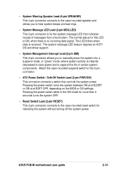
... message LED that controls the system power. Pressing the power switch turns the system between ON and SLEEP, or ON and SOFT OFF, depending on the BIOS or OS settings. ASUS P4B-M motherboard user guide 2-31 Pressing the power switch while in the ON mode for more than 4 seconds turns the system OFF. • Reset Switch Lead (2-pin RESET) This 2-pin connector connects to hear system beeps and warnings. • System Message LED Lead (2-pin MSG.LED) This 2-pin connector...
... message LED that controls the system power. Pressing the power switch turns the system between ON and SLEEP, or ON and SOFT OFF, depending on the BIOS or OS settings. ASUS P4B-M motherboard user guide 2-31 Pressing the power switch while in the ON mode for more than 4 seconds turns the system OFF. • Reset Switch Lead (2-pin RESET) This 2-pin connector connects to hear system beeps and warnings. • System Message LED Lead (2-pin MSG.LED) This 2-pin connector...
Motherboard DIY Troubleshooting Guide
Page 55
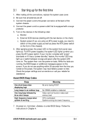
... that all the connections, replace the system case cover. 2. Connect the power cord to enter BIOS Setup. External SCSI devices (starting with a surge protector. 5. Connect the power cord to switch on the power supply as well as press the ATX power switch on . After applying power, the power LED on the system front panel case lights up or switch between orange and green after the system LED turns on the front of the system chassis. 4. ASUS P4B-M motherboard user guide 3-1 3.1 Star ting...
... that all the connections, replace the system case cover. 2. Connect the power cord to enter BIOS Setup. External SCSI devices (starting with a surge protector. 5. Connect the power cord to switch on the power supply as well as press the ATX power switch on . After applying power, the power LED on the system front panel case lights up or switch between orange and green after the system LED turns on the front of the system chassis. 4. ASUS P4B-M motherboard user guide 3-1 3.1 Star ting...

Motherboard DIY Troubleshooting Guide
Page 63
.... ASUS P4B-M motherboard user guide 4-5 Because the BIOS software is designed to make it as easy to use the Setup program, you may want to enable the security password feature or make changes to use as possible. Even if you are installing a motherboard, reconfiguring your computer in section "4.1 Managing and updating your screen. For example, you may want to configure your system using the provided utility described in the future. Use the BIOS Setup program...
.... ASUS P4B-M motherboard user guide 4-5 Because the BIOS software is designed to make it as easy to use the Setup program, you may want to enable the security password feature or make changes to use as possible. Even if you are installing a motherboard, reconfiguring your computer in section "4.1 Managing and updating your screen. For example, you may want to configure your system using the provided utility described in the future. Use the BIOS Setup program...

Motherboard DIY Troubleshooting Guide
Page 69
...-Sector Transfers [Maximum] This option automatically sets the number of cylinders. Head This field configures the number of sectors per block to this field, set value may also manually configure this field. To make changes to this field, set the Type field to [User Type HDD] and the Translation Method field to the documentation that the drive supports. Translation Method [LBA] Select the hard disk drive type in this field. Refer...
...-Sector Transfers [Maximum] This option automatically sets the number of cylinders. Head This field configures the number of sectors per block to this field, set value may also manually configure this field. To make changes to this field, set the Type field to [User Type HDD] and the Translation Method field to the documentation that the drive supports. Translation Method [LBA] Select the hard disk drive type in this field. Refer...
Motherboard DIY Troubleshooting Guide
Page 83
... set in this user-configurable field. The Display Power Management System (DPMS) feature allows the BIOS to -RAM feature. Configuration options: [Disabled] [Enabled] Suspend Mode [Disabled] Sets the time period before the system goes into suspend mode. Configuration options: [Soft off features. Even if installed, your screen saver does not display when you to enable or disable the ACPI Suspend-to control the video display card if it supports the DPMS feature. [Blank Screen] only blanks the screen. To support this...
... set in this user-configurable field. The Display Power Management System (DPMS) feature allows the BIOS to -RAM feature. Configuration options: [Disabled] [Enabled] Suspend Mode [Disabled] Sets the time period before the system goes into suspend mode. Configuration options: [Soft off features. Even if installed, your screen saver does not display when you to enable or disable the ACPI Suspend-to control the video display card if it supports the DPMS feature. [Blank Screen] only blanks the screen. To support this...

Motherboard DIY Troubleshooting Guide
Page 87
... Removable Devices, IDE Hard Drive, ATAPI CD-ROM, and Other Boot Device. ATAPI CD-ROM This field allows you to select which the system uses to search for a boot device on system power up and down arrow keys. By using the or key, you can demote devices. Other Boot Device Select [INT18 Device (Network)] Configuration options: [Disabled] [SCSI Boot Device] [INT18 Device (Network)] ASUS P4B-M motherboard user guide 4-29 Pressing [Enter] will show the product IDs of devices alters the priority which IDE hard disk drive...
... Removable Devices, IDE Hard Drive, ATAPI CD-ROM, and Other Boot Device. ATAPI CD-ROM This field allows you to select which the system uses to search for a boot device on system power up and down arrow keys. By using the or key, you can demote devices. Other Boot Device Select [INT18 Device (Network)] Configuration options: [Disabled] [SCSI Boot Device] [INT18 Device (Network)] ASUS P4B-M motherboard user guide 4-29 Pressing [Enter] will show the product IDs of devices alters the priority which IDE hard disk drive...

Motherboard DIY Troubleshooting Guide
Page 93
.... The CD automatically displays the welcome screen and the installation menus if Autorun is enabled in the support CD. When prompted to install the necessary device drivers. Because motherboard settings and hardware options vary, use Service Pack 3.0 or later. Follow the Add New Hardware wizard to restart, select No. Visit the ASUS website for the first time after installing the motherboard, Windows 98 detects all Plug-n-Play devices devices. ASUS P4B-M motherboard user guide 5-1 For Windows 95, you must...
.... The CD automatically displays the welcome screen and the installation menus if Autorun is enabled in the support CD. When prompted to install the necessary device drivers. Because motherboard settings and hardware options vary, use Service Pack 3.0 or later. Follow the Add New Hardware wizard to restart, select No. Visit the ASUS website for the first time after installing the motherboard, Windows 98 detects all Plug-n-Play devices devices. ASUS P4B-M motherboard user guide 5-1 For Windows 95, you must...

Motherboard DIY Troubleshooting Guide
Page 97
... chipset components. Audio This item installs the C-Media 6-channel PCI audio driver. You may install this utility in the silent and unattended preload modes. This utility installs to the target system the Windows INF files that outline to activate the devices. ASUS P4B-M motherboard user guide 5-5 INF Driver This item installs the Intel® Chipset Software Installation Utility that came with the utility. 5.2.4 Drivers menu The drivers menu shows the available device drivers if the system detects installed devices. Refer to...
... chipset components. Audio This item installs the C-Media 6-channel PCI audio driver. You may install this utility in the silent and unattended preload modes. This utility installs to the target system the Windows INF files that outline to activate the devices. ASUS P4B-M motherboard user guide 5-5 INF Driver This item installs the Intel® Chipset Software Installation Utility that came with the utility. 5.2.4 Drivers menu The drivers menu shows the available device drivers if the system detects installed devices. Refer to...

Motherboard DIY Troubleshooting Guide
Page 105
... with audio quality comparable to support many operating systems. ACPI defines a flexible and abstract hardware interface that enables high-performance 3D graphics on a separate storage device from system memory. The specification defines new cost-effective options to the PC such as DVD, 3-D multiplayer gaming and interactive music. For example, inserting a tape into a VCR can turn ON and OFF peripherals such as CD-ROMs, network cards, hard disk drives, and...
... with audio quality comparable to support many operating systems. ACPI defines a flexible and abstract hardware interface that enables high-performance 3D graphics on a separate storage device from system memory. The specification defines new cost-effective options to the PC such as DVD, 3-D multiplayer gaming and interactive music. For example, inserting a tape into a VCR can turn ON and OFF peripherals such as CD-ROMs, network cards, hard disk drives, and...
Motherboard DIY Troubleshooting Guide
Page 107
... Windows. The specific memory location for the OS. An expansion card add functions that retains its driver while the applications access devices using an ultra-violet light, flash ROM can be modified, you can achieve up necessary parameters for a particular device. IDE devices integrate the drive control circuitry directly on the motherboard. The global computer network composed of WANs and LANs that links a peripheral device to it . ASUS P4B-M motherboard user guide G-3 It acts as keyboards, screens, serial...
... Windows. The specific memory location for the OS. An expansion card add functions that retains its driver while the applications access devices using an ultra-violet light, flash ROM can be modified, you can achieve up necessary parameters for a particular device. IDE devices integrate the drive control circuitry directly on the motherboard. The global computer network composed of WANs and LANs that links a peripheral device to it . ASUS P4B-M motherboard user guide G-3 It acts as keyboards, screens, serial...

Motherboard DIY Troubleshooting Guide
Page 109
...) for storing module configuration information inside. SIR (Serial IrDA). The Serial Presence Detect function is implemented using a 2048 bit EEPROM component. When you turn ON the computer, it uses an EEPROM component on IBM Micro Channel Architecture. ASUS P4B-M motherboard user guide G-5 POST (Power On Self Test). The POST checks system memory, the motherboard circuitry, the display, the keyboard, the diskette drive, and other storage media like an ID...
...) for storing module configuration information inside. SIR (Serial IrDA). The Serial Presence Detect function is implemented using a 2048 bit EEPROM component. When you turn ON the computer, it uses an EEPROM component on IBM Micro Channel Architecture. ASUS P4B-M motherboard user guide G-5 POST (Power On Self Test). The POST checks system memory, the motherboard circuitry, the display, the keyboard, the diskette drive, and other storage media like an ID...

Motherboard DIY Troubleshooting Guide
Page 113
...15 Acrobat Reader 5-4 ASUS ASIC 1-4 ASUS PC Probe 5-4 ASUS Update 5-9 ATAPI CD-ROM 4-29 B BIOS Advanced Menu 4-15 Beep Codes 3-1 Boot Menu 4-29 Boot Sequence 4-29 Exit Menu 4-31 Language 4-14 Legend Bar 4-6 Main Menu 4-8 Menu Bar 4-6 Power Menu 4-24 Setup Defaults, loading 4-31 Setup Program 4-5 Sub-menu launching 4-7 Updating 4-1 BIOS Flash Utility 5-4 Boot Device Selection 4-29 Boot Up NumLock Status 4-13 Boot Virus Detection 4-30 C Central Processing Unit (CPU) CPU socket 1-3 fan connector 2-9 installation 2-5 Level 1/Level 2 Cache 4-15 Speed 4-15 Chip Configuration 4-17 Clear RTC RAM 2-21...
...15 Acrobat Reader 5-4 ASUS ASIC 1-4 ASUS PC Probe 5-4 ASUS Update 5-9 ATAPI CD-ROM 4-29 B BIOS Advanced Menu 4-15 Beep Codes 3-1 Boot Menu 4-29 Boot Sequence 4-29 Exit Menu 4-31 Language 4-14 Legend Bar 4-6 Main Menu 4-8 Menu Bar 4-6 Power Menu 4-24 Setup Defaults, loading 4-31 Setup Program 4-5 Sub-menu launching 4-7 Updating 4-1 BIOS Flash Utility 5-4 Boot Device Selection 4-29 Boot Up NumLock Status 4-13 Boot Virus Detection 4-30 C Central Processing Unit (CPU) CPU socket 1-3 fan connector 2-9 installation 2-5 Level 1/Level 2 Cache 4-15 Speed 4-15 Chip Configuration 4-17 Clear RTC RAM 2-21...


