
CUSI-M User Manual
Page 2
...on the following page. Copyright © 2000 ASUSTeK COMPUTER INC. For previous or updated manuals, BIOS, drivers, or product release information, contact ASUS at http://www.asus.com.tw or through any means, except documentation kept by the purchaser for each product design represented... TO CHANGE AT ANY TIME WITHOUT NOTICE, AND SHOULD NOT BE CONSTRUED AS A COMMITMENT BY ASUS. Product Name: ASUS CUSI-M Manual Revision: 1.01 E605 Release Date: September 2000 2 ASUS CUSI-M User's Manual Manual revisions are registered trademarks of Adobe Systems Incorporated. IN NO EVENT SHALL...
...on the following page. Copyright © 2000 ASUSTeK COMPUTER INC. For previous or updated manuals, BIOS, drivers, or product release information, contact ASUS at http://www.asus.com.tw or through any means, except documentation kept by the purchaser for each product design represented... TO CHANGE AT ANY TIME WITHOUT NOTICE, AND SHOULD NOT BE CONSTRUED AS A COMMITMENT BY ASUS. Product Name: ASUS CUSI-M Manual Revision: 1.01 E605 Release Date: September 2000 2 ASUS CUSI-M User's Manual Manual revisions are registered trademarks of Adobe Systems Incorporated. IN NO EVENT SHALL...
CUSI-M User Manual
Page 4
... First Use of the Computer System 41 4.1.2 Updating BIOS Procedures 42 4.2 BIOS Setup Program 45 4.2.1 BIOS Menu Bar 46 4.2.2 Legend Bar 46 4.3 Main Menu 48 4.3.1 Primary & Secondary Master/Slave 49 4.3.2 Keyboard Features 52 4 ASUS CUSI-M User's Manual CONTENTS 1. FEATURES 8 2.1 The ASUS CUSI-M 8 2.1.1 Specifications 8 2.1.2 Specifications-Optional Components 9 2.1.3 Performance 10 2.1.4 Intelligence 11 2.2 CUSI-M Motherboard Components 12 3. INTRODUCTION 7 1.1 How This Manual...
... First Use of the Computer System 41 4.1.2 Updating BIOS Procedures 42 4.2 BIOS Setup Program 45 4.2.1 BIOS Menu Bar 46 4.2.2 Legend Bar 46 4.3 Main Menu 48 4.3.1 Primary & Secondary Master/Slave 49 4.3.2 Keyboard Features 52 4 ASUS CUSI-M User's Manual CONTENTS 1. FEATURES 8 2.1 The ASUS CUSI-M 8 2.1.1 Specifications 8 2.1.2 Specifications-Optional Components 9 2.1.3 Performance 10 2.1.4 Intelligence 11 2.2 CUSI-M Motherboard Components 12 3. INTRODUCTION 7 1.1 How This Manual...

CUSI-M User Manual
Page 7
... 5. 1. Intructions on setting up the BIOS Intructions on setting up the included software Reference material for (1) 5.25" and (2) 3.5" floppy disk drives (1) ASUS 3-port USB connector set with bracket (1) I/O Shield (1) Bag of spare jumpers (1) Support drivers and utilities (1) This Motherboard User's Manual Optional Items ASUS consumer infrared set Modem riser ASUS CUSI-M User's Manual 7 If you...
... 5. 1. Intructions on setting up the BIOS Intructions on setting up the included software Reference material for (1) 5.25" and (2) 3.5" floppy disk drives (1) ASUS 3-port USB connector set with bracket (1) I/O Shield (1) Bag of spare jumpers (1) Support drivers and utilities (1) This Motherboard User's Manual Optional Items ASUS consumer infrared set Modem riser ASUS CUSI-M User's Manual 7 If you...
CUSI-M User Manual
Page 9
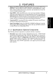
ASUS CUSI-M User's Manual 9 With this chip onboard, no external CODEC is needed. Provides Vcore and CPU/ SDRAM frequency adjustments, boot block write protection, and HD/SCSI/...: Provides C-Media Electronics Inc.'s CMI-8738 PCI 3D Extension Positional Audio Chip. 2. FEATURES • Enhanced ACPI & Anti-Boot Virus Protection: Programmable BIOS (Flash EEPROM), offering enhanced ACPI for virtually automatic setup. • Smart BIOS: 2Mbit flash ROM gives a new easy-to-use interface which provides more control and protection over the motherboard.
ASUS CUSI-M User's Manual 9 With this chip onboard, no external CODEC is needed. Provides Vcore and CPU/ SDRAM frequency adjustments, boot block write protection, and HD/SCSI/...: Provides C-Media Electronics Inc.'s CMI-8738 PCI 3D Extension Positional Audio Chip. 2. FEATURES • Enhanced ACPI & Anti-Boot Virus Protection: Programmable BIOS (Flash EEPROM), offering enhanced ACPI for virtually automatic setup. • Smart BIOS: 2Mbit flash ROM gives a new easy-to-use interface which provides more control and protection over the motherboard.
CUSI-M User Manual
Page 10
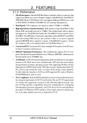
...using UltraDMA/33 Bus Master IDE can be used. • New Compliancy: Both the BIOS and hardware levels of ACPI, an ACPI-supported OS, such as required by PC 99. 10 ASUS CUSI-M User's Manual With these features implemented in two channels. UltraDMA/66 is backward compatible ...Color-coded connectors and descriptive icons make identification easy as Windows 98/2000/Millenium, must be ready around the clock, yet satisfy all ASUS smart series motherboards. This motherboard with existing DMA devices and systems so there is also implemented on all the energy saving standards. 2....
...using UltraDMA/33 Bus Master IDE can be used. • New Compliancy: Both the BIOS and hardware levels of ACPI, an ACPI-supported OS, such as required by PC 99. 10 ASUS CUSI-M User's Manual With these features implemented in two channels. UltraDMA/66 is backward compatible ...Color-coded connectors and descriptive icons make identification easy as Windows 98/2000/Millenium, must be ready around the clock, yet satisfy all ASUS smart series motherboards. This motherboard with existing DMA devices and systems so there is also implemented on all the energy saving standards. 2....

CUSI-M User Manual
Page 11
... as Windows 98/ Millenium, Windows NT/2000, and OS/2, require much more efficiently. • Dual Function Power Button: Through BIOS, the power button can access any information from a fax/modem. Voltage specifications are used up can determine if a message has been... computer to ensure proper system configuration and management. • System Resources Alert: Today's operating systems, such as the "Stand by" (a.k.a. ASUS CUSI-M User's Manual 11 FEATURES Intelligence 2. Regardless of the setting, pushing the power button for future processors, so monitoring is necessary to be ...
... as Windows 98/ Millenium, Windows NT/2000, and OS/2, require much more efficiently. • Dual Function Power Button: Through BIOS, the power button can access any information from a fax/modem. Voltage specifications are used up can determine if a message has been... computer to ensure proper system configuration and management. • System Resources Alert: Today's operating systems, such as the "Stand by" (a.k.a. ASUS CUSI-M User's Manual 11 FEATURES Intelligence 2. Regardless of the setting, pushing the power button for future processors, so monitoring is necessary to be ...
CUSI-M User Manual
Page 12
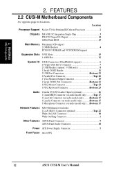
FEATURES 2.2 CUSI-M Motherboard Components See opposite page for Pentium III/Celeron Processors 2 Chipsets SiS 630E 3C Integration Single Chip 3 ITE 8705 Super I/O Chipset 14 2Mbit Flash BIOS 13 Main Memory Maximum 1GB support 2 DIMM Sockets 4 PC100/133 SDRAM and VCM SDRAM support...Top) 22 Wake-On-LAN Connector 10 Wake-On-Ring Connector 1 Other Features ASUS iPanel Connector 9 ASUS iPanel Audio Connector 18 Power ATX Power Supply Connector 5 Form Factor microATX 12 ASUS CUSI-M User's Manual FEATURES MB Components 2. Location Processor Support Socket 370 for locations. ...
FEATURES 2.2 CUSI-M Motherboard Components See opposite page for Pentium III/Celeron Processors 2 Chipsets SiS 630E 3C Integration Single Chip 3 ITE 8705 Super I/O Chipset 14 2Mbit Flash BIOS 13 Main Memory Maximum 1GB support 2 DIMM Sockets 4 PC100/133 SDRAM and VCM SDRAM support...Top) 22 Wake-On-LAN Connector 10 Wake-On-Ring Connector 1 Other Features ASUS iPanel Connector 9 ASUS iPanel Audio Connector 18 Power ATX Power Supply Connector 5 Form Factor microATX 12 ASUS CUSI-M User's Manual FEATURES MB Components 2. Location Processor Support Socket 370 for locations. ...
CUSI-M User Manual
Page 14
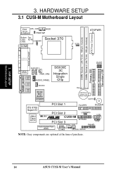
H/W SETUP Motherboard Layout 3. JP3 JP1 JP2 Secondary IDE JP0 3. HARDWARE SETUP 3.1 CUSI-M Motherboard Layout 01 PS/2 CPU_FAN WOR T: Mouse B: Keyboard PWRTMP Bottom: Top: USB1 RJ-45 Socket 370 USB2 USBPWR1 COM1 ATXPWR SCPU ATX Power Connector ... Audio Chipset Row 0 1 2 3 CR2032 3V Lithium Cell CMOS Power CLRTC Primary IDE PCI Slot 1 FLOPPY BUZZER ITE 8705 Super I/O 2Mbit Flash BIOS PCI Slot 2 USBPWR0 USB1 JEN ® CUSI-M PCI Slot 3 AFPANEL USB2 Audio Modem Riser (AMR) WOL_CON PANEL COM2 CH_FAN IDELED NOTE: Gray components are optional at the time of...
H/W SETUP Motherboard Layout 3. JP3 JP1 JP2 Secondary IDE JP0 3. HARDWARE SETUP 3.1 CUSI-M Motherboard Layout 01 PS/2 CPU_FAN WOR T: Mouse B: Keyboard PWRTMP Bottom: Top: USB1 RJ-45 Socket 370 USB2 USBPWR1 COM1 ATXPWR SCPU ATX Power Connector ... Audio Chipset Row 0 1 2 3 CR2032 3V Lithium Cell CMOS Power CLRTC Primary IDE PCI Slot 1 FLOPPY BUZZER ITE 8705 Super I/O 2Mbit Flash BIOS PCI Slot 2 USBPWR0 USB1 JEN ® CUSI-M PCI Slot 3 AFPANEL USB2 Audio Modem Riser (AMR) WOL_CON PANEL COM2 CH_FAN IDELED NOTE: Gray components are optional at the time of...
CUSI-M User Manual
Page 16
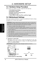
Use a grounded wrist strap before you plug in detail how to change your motherboard's function settings through the BIOS setup (see 4.4 Advanced Menu) IMPORTANT: In JumperFree mode, all jumpers must be made through the use of your hands to a safely grounded object or to [1-2]. ... components. 4. If you work on the inside. 2. 3. To protect them against damage from the system. 5. H/W SETUP Motherboard Settings 01 JP3 JP1 JP2 JP0 3 2 1 ® CUSI-M CUSI-M JumperFree™ Mode Setting JEN Jumperless Mode Jumper Mode 12 12 16 ASUS CUSI-M User's Manual WARNING!
Use a grounded wrist strap before you plug in detail how to change your motherboard's function settings through the BIOS setup (see 4.4 Advanced Menu) IMPORTANT: In JumperFree mode, all jumpers must be made through the use of your hands to a safely grounded object or to [1-2]. ... components. 4. If you work on the inside. 2. 3. To protect them against damage from the system. 5. H/W SETUP Motherboard Settings 01 JP3 JP1 JP2 JP0 3 2 1 ® CUSI-M CUSI-M JumperFree™ Mode Setting JEN Jumperless Mode Jumper Mode 12 12 16 ASUS CUSI-M User's Manual WARNING!
CUSI-M User Manual
Page 20
...3.5 System Memory (DIMM) NOTE: No hardware or BIOS setup is recommended through Configure SDRAM Timing by SPD (see 4.4.2 Advanced Chipset Setup). tended Data Output) chips. • BIOS shows SDRAM memory on the motherboard. Memory speed setup ...is required after adding or removing memory. This motherboard uses only Dual Inline Memory Modules (DIMMs). 3. H/W SETUP System Memory 3. One side (with 9 chips per side (standard 8 chips/side + 1 ECC chip). double-sided come in 32, 64, 128, 256, 512MB. 20 ASUS CUSI...
...3.5 System Memory (DIMM) NOTE: No hardware or BIOS setup is recommended through Configure SDRAM Timing by SPD (see 4.4.2 Advanced Chipset Setup). tended Data Output) chips. • BIOS shows SDRAM memory on the motherboard. Memory speed setup ...is required after adding or removing memory. This motherboard uses only Dual Inline Memory Modules (DIMMs). 3. H/W SETUP System Memory 3. One side (with 9 chips per side (standard 8 chips/side + 1 ECC chip). double-sided come in 32, 64, 128, 256, 512MB. 20 ASUS CUSI...
CUSI-M User Manual
Page 23
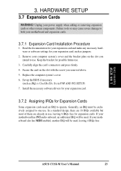
... In a standard design, there are 16 IRQs available but most of them are already in PNP AND PCI SETUP) 7. H/W SETUP Expansion Cards ASUS CUSI-M User's Manual 23 Keep the bracket for expansion cards. Read the documentation for your expansion card and make any necessary hardware or software settings for...your expansion card, such as IRQ xx Used By ISA: Yes in use, leaving 6 IRQs free for possible future use. 3. Set up the BIOS if necessary (such as jumpers. 2. If your power supply when adding or removing expansion cards or other system components. Failure to do so may ...
... In a standard design, there are 16 IRQs available but most of them are already in PNP AND PCI SETUP) 7. H/W SETUP Expansion Cards ASUS CUSI-M User's Manual 23 Keep the bracket for expansion cards. Read the documentation for your expansion card and make any necessary hardware or software settings for...your expansion card, such as IRQ xx Used By ISA: Yes in use, leaving 6 IRQs free for possible future use. 3. Set up the BIOS if necessary (such as jumpers. 2. If your power supply when adding or removing expansion cards or other system components. Failure to do so may ...
CUSI-M User Manual
Page 30
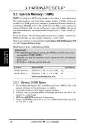
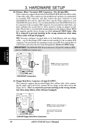
.../s transfer rates. IMPORTANT: UltraDMA/66 IDE devices must configure the second drive to PIN 1. ® CUSI-M PIN 1 CUSI-M Floppy Disk Drive Connector 30 ASUS CUSI-M User's Manual 3. BIOS now supports specific device bootup (see 4.4.1 Advanced CMOS Setup). (Pin 20 is recommended that non-UltraDMA/... the floppy ribbon cable to Slave mode by setting its jumper accordingly. You may configure two hard disks to PIN 1 ® CUSI-M CUSI-M IDE Connectors PIN 1 11) Floppy Disk Drive Connector (34-1pin FLOPPY) This connector supports the provided floppy drive ribbon cable. ...
.../s transfer rates. IMPORTANT: UltraDMA/66 IDE devices must configure the second drive to PIN 1. ® CUSI-M PIN 1 CUSI-M Floppy Disk Drive Connector 30 ASUS CUSI-M User's Manual 3. BIOS now supports specific device bootup (see 4.4.1 Advanced CMOS Setup). (Pin 20 is recommended that non-UltraDMA/... the floppy ribbon cable to Slave mode by setting its jumper accordingly. You may configure two hard disks to PIN 1 ® CUSI-M CUSI-M IDE Connectors PIN 1 11) Floppy Disk Drive Connector (34-1pin FLOPPY) This connector supports the provided floppy drive ribbon cable. ...
CUSI-M User Manual
Page 39
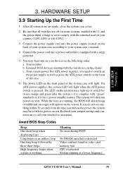
... No error during POST No DRAM installed or detected Video card not found or video card memory bad CPU overheated System running , the BIOS will alarm beeps or additional messages will then run power-on the screen. External SCSI devices (starting with the last device on the ... standards or if it has a power standby feature. Connect the power supply cord into a power outlet that all connections are running at a lower frequency ASUS CUSI-M User's Manual 39 Your system power. For ATX power supplies, the system LED will light. The LED on the monitor may have failed a power...
... No error during POST No DRAM installed or detected Video card not found or video card memory bad CPU overheated System running , the BIOS will alarm beeps or additional messages will then run power-on the screen. External SCSI devices (starting with the last device on the ... standards or if it has a power standby feature. Connect the power supply cord into a power outlet that all connections are running at a lower frequency ASUS CUSI-M User's Manual 39 Your system power. For ATX power supplies, the system LED will light. The LED on the monitor may have failed a power...
CUSI-M User Manual
Page 40
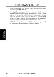
Follow the instructions in 4. If you can now safely turn off the power switch. BIOS SETUP. * Powering Off your computer: You must first exit or shut down . H/W SETUP Powering Up 40 ASUS CUSI-M User's Manual The power supply should turn off your computer" will not appear when shutting down with ATX power supplies. 3. During... system. 3. HARDWARE SETUP 7. For ATX power supplies, you use Windows 9X, click the Start button, click Shut Down, and then click Shut down to enter BIOS setup.
Follow the instructions in 4. If you can now safely turn off the power switch. BIOS SETUP. * Powering Off your computer: You must first exit or shut down . H/W SETUP Powering Up 40 ASUS CUSI-M User's Manual The power supply should turn off your computer" will not appear when shutting down with ATX power supplies. 3. During... system. 3. HARDWARE SETUP 7. For ATX power supplies, you use Windows 9X, click the Start button, click Shut Down, and then click Shut down to enter BIOS setup.
CUSI-M User Manual
Page 41
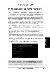
...not supported by uploading a new BIOS file to a bootable floppy disk in DOS mode. This file works only in Windows and will not work with certain memory drivers that you boot from the floppy disk. Type FORMAT A:/S at the DOS prompt to the disk. 2. ASUS CUSI-M User's Manual 41 To ...determine the BIOS version of the Computer System It is recommended that may be programmed by the Flash Memory Writer utility. It will not work...
...not supported by uploading a new BIOS file to a bootable floppy disk in DOS mode. This file works only in Windows and will not work with certain memory drivers that you boot from the floppy disk. Type FORMAT A:/S at the DOS prompt to the disk. 2. ASUS CUSI-M User's Manual 41 To ...determine the BIOS version of the Computer System It is recommended that may be programmed by the Flash Memory Writer utility. It will not work...
CUSI-M User Manual
Page 42
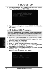
... Type the filename of your new BIOS and the path, for example, A:\XXX-XX.XXX and then press . 4.1.2 Updating BIOS Procedures WARNING! BIOS SETUP 5. BIOS SETUP Updating BIOS 42 ASUS CUSI-M User's Manual Save Current BIOS to File from the Internet (WWW or FTP) (see ASUS CONTACT INFORMATION on page 3 for.... At the "A:\" prompt, type AFLASH and then press . 4. NOTE: To cancel this operation, press . 4. The Save Current BIOS To File screen appears. 6. Download an updated ASUS BIOS file from the Main menu and press . At the Main Menu, type 2 and then press . 4. Only update your...
... Type the filename of your new BIOS and the path, for example, A:\XXX-XX.XXX and then press . 4.1.2 Updating BIOS Procedures WARNING! BIOS SETUP 5. BIOS SETUP Updating BIOS 42 ASUS CUSI-M User's Manual Save Current BIOS to File from the Internet (WWW or FTP) (see ASUS CONTACT INFORMATION on page 3 for.... At the "A:\" prompt, type AFLASH and then press . 4. NOTE: To cancel this operation, press . 4. The Save Current BIOS To File screen appears. 6. Download an updated ASUS BIOS file from the Main menu and press . At the Main Menu, type 2 and then press . 4. Only update your...
CUSI-M User Manual
Page 43
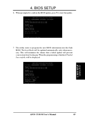
This will minimize the chance that a failed update will be updated automatically only when necessary. BIOS SETUP Updating BIOS ASUS CUSI-M User's Manual 43 The boot block will be displayed. 4. When the programming is finished, Flashed Successfully will prevent your system from booting up. When prompted to confirm the BIOS update, press Y to program the new BIOS information into the flash ROM. BIOS SETUP 6. The utility starts to start the update. 7. 4.
This will minimize the chance that a failed update will be updated automatically only when necessary. BIOS SETUP Updating BIOS ASUS CUSI-M User's Manual 43 The boot block will be displayed. 4. When the programming is finished, Flashed Successfully will prevent your system from booting up. When prompted to confirm the BIOS update, press Y to program the new BIOS information into the flash ROM. BIOS SETUP 6. The utility starts to start the update. 7. 4.
CUSI-M User Manual
Page 44
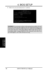
If this might prevent your system will need servicing. 4. Just repeat the process, and if the problem still persists, update the original BIOS file you encounter problems while updating the new BIOS, DO NOT turn off your system since this happens, your system from booting up . If you saved to disk above. If the Flash Memory Writer utility was not able to successfully update a complete BIOS file, your system may not be able to continue. 4. Follow the onscreen instructions to boot up . BIOS SETUP Updating BIOS 44 ASUS CUSI-M User's Manual WARNING! BIOS SETUP 8.
If this might prevent your system will need servicing. 4. Just repeat the process, and if the problem still persists, update the original BIOS file you encounter problems while updating the new BIOS, DO NOT turn off your system since this happens, your system from booting up . If you saved to disk above. If the Flash Memory Writer utility was not able to successfully update a complete BIOS file, your system may not be able to continue. 4. Follow the onscreen instructions to boot up . BIOS SETUP Updating BIOS 44 ASUS CUSI-M User's Manual WARNING! BIOS SETUP 8.
CUSI-M User Manual
Page 45
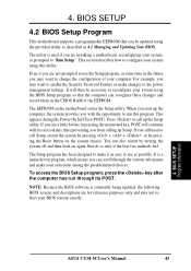
... first two methods fail. The EEPROM on the system chassis. The Setup program has been designed to the power management settings. BIOS SETUP Program Information ASUS CUSI-M User's Manual 45 BIOS SETUP 4.2 BIOS Setup Program This motherboard supports a programmable EEPROM that the computer can also restart by pressing the Reset button on the motherboard stores...
... first two methods fail. The EEPROM on the system chassis. The Setup program has been designed to the power management settings. BIOS SETUP Program Information ASUS CUSI-M User's Manual 45 BIOS SETUP 4.2 BIOS Setup Program This motherboard supports a programmable EEPROM that the computer can also restart by pressing the Reset button on the motherboard stores...
CUSI-M User Manual
Page 46
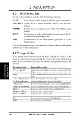
... Key(s) Function Description or Displays the General Help screen from anywhere in the legend bar with the following table lists the keys found in the BIOS Setup Jumps to the Exit menu or returns to the main menu from a submenu ← or → (keypad arrow) Selects the menu... field or Moves the cursor to the last field Resets the current screen to locate and load the Operating System. BIOS SETUP Menu Introduction 46 ASUS CUSI-M User's Manual BIOS SETUP 4.2.1 BIOS Menu Bar The top of the Setup screen you to the advanced features. To access the menu bar items, press...
... Key(s) Function Description or Displays the General Help screen from anywhere in the legend bar with the following table lists the keys found in the BIOS Setup Jumps to the Exit menu or returns to the main menu from a submenu ← or → (keypad arrow) Selects the menu... field or Moves the cursor to the last field Resets the current screen to locate and load the Operating System. BIOS SETUP Menu Introduction 46 ASUS CUSI-M User's Manual BIOS SETUP 4.2.1 BIOS Menu Bar The top of the Setup screen you to the advanced features. To access the menu bar items, press...


