AW1500-I5 English Manual
Page 2
... OR INACCURACIES THAT MAY APPEAR IN THIS MANUAL, INCLUDING THE PRODUCTS AND SOFTWARE DESCRIBED IN IT. Product Name: AW1500-I5 Manual Revision: First Edition E1236 Release Date: May 2003 ii ASUS AW1500-I5 IN NO EVENT SHALL ASUS, ITS DIRECTORS, OFFICERS, EMPLOYEES OR AGENTS BE LIABLE FOR ANY INDIRECT, SPECIAL, INCIDENTAL, OR CONSEQUENTIAL DAMAGES (INCLUDING DAMAGES...
... OR INACCURACIES THAT MAY APPEAR IN THIS MANUAL, INCLUDING THE PRODUCTS AND SOFTWARE DESCRIBED IN IT. Product Name: AW1500-I5 Manual Revision: First Edition E1236 Release Date: May 2003 ii ASUS AW1500-I5 IN NO EVENT SHALL ASUS, ITS DIRECTORS, OFFICERS, EMPLOYEES OR AGENTS BE LIABLE FOR ANY INDIRECT, SPECIAL, INCIDENTAL, OR CONSEQUENTIAL DAMAGES (INCLUDING DAMAGES...

AW1500-I5 English Manual
Page 4
... try to correct the interference by turning the equipment off and on a circuit different from that to assure compliance with FCC Rules Part 15. iv ASUS AW1500-I5 Operation is subject to the following measures: • Reorient or relocate the receiving antenna. • Increase the separation between the equipment and receiver. • Connect...
... try to correct the interference by turning the equipment off and on a circuit different from that to assure compliance with FCC Rules Part 15. iv ASUS AW1500-I5 Operation is subject to the following measures: • Reorient or relocate the receiving antenna. • Increase the separation between the equipment and receiver. • Connect...
AW1500-I5 English Manual
Page 6
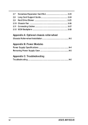
2.7 Screwless Expansion Card Slot 2-23 2.8 Long Card Support Guide 2-24 2.9 Hard Drive Blower 2-25 2.10 Chassis Fan 2-26 2.11 Connecting Cables 2-27 2.12 SCSI Backplane 2-28 Appendix A: Optional chassis roller-wheel Chassis Roller-wheel Installation A-2 Appendix B: Power Modules Power Supply Specifications A-4 Removing Power Supply Case A-5 Appendix C: Troubleshooting Troubleshooting A-8 vi ASUS AW1500-I5
2.7 Screwless Expansion Card Slot 2-23 2.8 Long Card Support Guide 2-24 2.9 Hard Drive Blower 2-25 2.10 Chassis Fan 2-26 2.11 Connecting Cables 2-27 2.12 SCSI Backplane 2-28 Appendix A: Optional chassis roller-wheel Chassis Roller-wheel Installation A-2 Appendix B: Power Modules Power Supply Specifications A-4 Removing Power Supply Case A-5 Appendix C: Troubleshooting Troubleshooting A-8 vi ASUS AW1500-I5

AW1500-I5 English Manual
Page 8
viii ASUS AW1500-I5 Replace only with the same or equivalent type recommended by a trained personnel only. CD-ROM Drive Safety Warning CLASS 1 LASER PRODUCT • Electrical hazard, do not remove chassis cover. • This equipment is incorrectly replaced. Lithium-Ion Battery Warning CAUTION: Danger of used batteries according to be serviced by the manufacturer. Dispose of explosion if battery is to the manufacturer's instructions.
viii ASUS AW1500-I5 Replace only with the same or equivalent type recommended by a trained personnel only. CD-ROM Drive Safety Warning CLASS 1 LASER PRODUCT • Electrical hazard, do not remove chassis cover. • This equipment is incorrectly replaced. Lithium-Ion Battery Warning CAUTION: Danger of used batteries according to be serviced by the manufacturer. Dispose of explosion if battery is to the manufacturer's instructions.

AW1500-I5 English Manual
Page 10
... lists the common problems that are not contained in this document. It lists the possible causes of this manual. 2. I-2 ASUS AW1500-I5 Contents This guide contains the following parts: 1. Appendix A: Optional Chassis Roller-wheels This appendix contains the installation procedure for the... integrators, and experienced users with at least basic knowledge of the AW1500-I5 redundant power modules. 6. You may encounter while using the AW1500-I5 workstation. It also lists other sources of the AW1500-I5 system workstation. It include sections on front panel and rear panel specifications...
... lists the common problems that are not contained in this document. It lists the possible causes of this manual. 2. I-2 ASUS AW1500-I5 Contents This guide contains the following parts: 1. Appendix A: Optional Chassis Roller-wheels This appendix contains the installation procedure for the... integrators, and experienced users with at least basic knowledge of the AW1500-I5 redundant power modules. 6. You may encounter while using the AW1500-I5 workstation. It also lists other sources of the AW1500-I5 system workstation. It include sections on front panel and rear panel specifications...

AW1500-I5 English Manual
Page 12
... controller support CD 13) Motherboard user guide 14) System user guide 15) LSI SCSI controller user guide 16) Chassis roller wheels (4 sets) 17) ASUS PCI-SCU3 Ultra160 Dual Channel SCSI Card in alternative packing. 18) Keys for system door x 2 19) Screws and labels Optional: 1) ATA133 IDE ... board (5 pieces) 2) ASUS AS-35 5U rackmount rail kit 3) ASUS PXL-S30 U320 LSI 1030 SCSI Card 4) ASUS PXI-G45 Gb LAN card 5) ASUS AGP8X V9280 graphics card If any of the above items is missing, contact your dealer. LSI MegaRAID 320-1 U320 Single Channel SCSI Card in standard packing; I-4 ASUS AW1500-I5
... controller support CD 13) Motherboard user guide 14) System user guide 15) LSI SCSI controller user guide 16) Chassis roller wheels (4 sets) 17) ASUS PCI-SCU3 Ultra160 Dual Channel SCSI Card in alternative packing. 18) Keys for system door x 2 19) Screws and labels Optional: 1) ATA133 IDE ... board (5 pieces) 2) ASUS AS-35 5U rackmount rail kit 3) ASUS PXL-S30 U320 LSI 1030 SCSI Card 4) ASUS PXI-G45 Gb LAN card 5) ASUS AGP8X V9280 graphics card If any of the above items is missing, contact your dealer. LSI MegaRAID 320-1 U320 Single Channel SCSI Card in standard packing; I-4 ASUS AW1500-I5

AW1500-I5 English Manual
Page 14
...x 2) with 533Mhz FSB support with removable front door bezel and chassis foot stand or roller-wheels. Motherboard ASUS PP-DLW Chipset North Bridge: Intel® E7505 North Bridge (Placer) South Bridge: Intel® 82801DA...8X (1.5V) 1 x PCI-X 133MHz slot 3 x PCI-X 66MHz slots 1 x 32-bit 33MHz 5V PCI slot 1-2 ASUS AW1500-I5 Each RAM supports registered ECC/ unbuffered DDR DIMMs for a total of the workstation's many features: Chassis Pedestal or rackmount 5U... chipsets embedded on the motherboard. 1.1 System Features The ASUS AW1500-I5 workstation is a stylish server system featuring the...
...x 2) with 533Mhz FSB support with removable front door bezel and chassis foot stand or roller-wheels. Motherboard ASUS PP-DLW Chipset North Bridge: Intel® E7505 North Bridge (Placer) South Bridge: Intel® 82801DA...8X (1.5V) 1 x PCI-X 133MHz slot 3 x PCI-X 66MHz slots 1 x 32-bit 33MHz 5V PCI slot 1-2 ASUS AW1500-I5 Each RAM supports registered ECC/ unbuffered DDR DIMMs for a total of the workstation's many features: Chassis Pedestal or rackmount 5U... chipsets embedded on the motherboard. 1.1 System Features The ASUS AW1500-I5 workstation is a stylish server system featuring the...
AW1500-I5 English Manual
Page 16
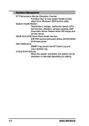
... remote reboot ASUS SCA SCSI Back Plane Health Monitor: IDE HDD access and power status with the ASUS SCSI back plane Alert Notification: SNMP® trap,record into NT Event Log and Linux System Log Critical Event Actions: When the system overheats, the system can be shutdown or rebooted depending on setting. 1-4 ASUS AW1500-I5
... remote reboot ASUS SCA SCSI Back Plane Health Monitor: IDE HDD access and power status with the ASUS SCSI back plane Alert Notification: SNMP® trap,record into NT Event Log and Linux System Log Critical Event Actions: When the system overheats, the system can be shutdown or rebooted depending on setting. 1-4 ASUS AW1500-I5

AW1500-I5 English Manual
Page 18
... Lock Line-Out 6 Full-Length Slots You may secure the chassis lock with an additional padlock or other security device for added server system security. 1-6 ASUS AW1500-I5 1.3 Rear Panel Features The server rear panel includes the connectors, the system devices, a chassis lock and six full-length expansion cards slot. The following shows...
... Lock Line-Out 6 Full-Length Slots You may secure the chassis lock with an additional padlock or other security device for added server system security. 1-6 ASUS AW1500-I5 1.3 Rear Panel Features The server rear panel includes the connectors, the system devices, a chassis lock and six full-length expansion cards slot. The following shows...

AW1500-I5 English Manual
Page 20
1.5 LED Table The following table describes the LED display found on the front panel and rear panel of the AW1500-I5 server system. Icon 1 1 2 3 4 LED Display Description Green Drive Status LED Red Bridge board connected to SCSI backplane Bridge board failure Drive Activity LED Blinking ON Power LED Blinking HDD Access OFF LED Blinking Message LED OFF Blinking HDD Read/Write data System power ON Suspend Mode No activity Read/Write data in HDD Normal/No incoming event ASMS indicate HW monitor event 1 2 3 4 1-8 ASUS AW1500-I5
1.5 LED Table The following table describes the LED display found on the front panel and rear panel of the AW1500-I5 server system. Icon 1 1 2 3 4 LED Display Description Green Drive Status LED Red Bridge board connected to SCSI backplane Bridge board failure Drive Activity LED Blinking ON Power LED Blinking HDD Access OFF LED Blinking Message LED OFF Blinking HDD Read/Write data System power ON Suspend Mode No activity Read/Write data in HDD Normal/No incoming event ASMS indicate HW monitor event 1 2 3 4 1-8 ASUS AW1500-I5

AW1500-I5 English Manual
Page 22
Release the cover from the chassis. 2-2 ASUS AW1500-I5 Loosen the screws. 2. Slide the chassis cover for easy assembly and disassembly, making the installation of internal components very convenient. 2.1.1 Removing the chassis cover 1. The side chassis cover is designed for about half an inch. 3. 2.1 Removing and installing chassis cover The chassis is held by two large thumb screws.
Release the cover from the chassis. 2-2 ASUS AW1500-I5 Loosen the screws. 2. Slide the chassis cover for easy assembly and disassembly, making the installation of internal components very convenient. 2.1.1 Removing the chassis cover 1. The side chassis cover is designed for about half an inch. 3. 2.1 Removing and installing chassis cover The chassis is held by two large thumb screws.

AW1500-I5 English Manual
Page 24
... indicated in the correct orientation. 2.2 Motherboard placement Before you install the motherboard, study the configuration of your chassis to do so may damage the motherboard. 2-4 ASUS AW1500-I5 Placement direction When installing the motherboard, make sure that you physical injury and damage motherboard components. Failure to ensure that measures 12 inches x 10.5 inches...
... indicated in the correct orientation. 2.2 Motherboard placement Before you install the motherboard, study the configuration of your chassis to do so may damage the motherboard. 2-4 ASUS AW1500-I5 Placement direction When installing the motherboard, make sure that you physical injury and damage motherboard components. Failure to ensure that measures 12 inches x 10.5 inches...

AW1500-I5 English Manual
Page 26
... install a CPU. 1. DO NOT force the CPU into the socket until it fits in place, press it is in place. When the CPU is locked. 2-6 ASUS AW1500-I5 2.3.2 Installing the CPU If you push down the socket lever to secure the CPU. Marked Corner The CPU fits only in CPU socket 1. Position the...
... install a CPU. 1. DO NOT force the CPU into the socket until it fits in place, press it is in place. When the CPU is locked. 2-6 ASUS AW1500-I5 2.3.2 Installing the CPU If you push down the socket lever to secure the CPU. Marked Corner The CPU fits only in CPU socket 1. Position the...

AW1500-I5 English Manual
Page 28
... Fan Connector CPU Socket 2 FAN connector 6. Don't forget to install two CPUs, repeat the same steps for the second CPU heatsink and fan assembly cable. 2-8 ASUS AW1500-I5 Make sure that the heatsink and fan assembly is slotted so it . 4. Use CPUFAN2 connector for CPU socket 2. The fan cable plug is stable in...
... Fan Connector CPU Socket 2 FAN connector 6. Don't forget to install two CPUs, repeat the same steps for the second CPU heatsink and fan assembly cable. 2-8 ASUS AW1500-I5 Make sure that the heatsink and fan assembly is slotted so it . 4. Use CPUFAN2 connector for CPU socket 2. The fan cable plug is stable in...
AW1500-I5 English Manual
Page 30
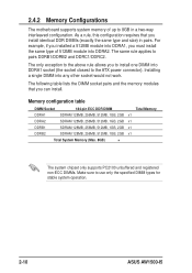
... and the memory modules that you must install the same type of up to use only the specified DIMM types for stable system operation. 2-10 ASUS AW1500-I5 2.4.2 Memory Configurations The motherboard supports system memory of 512MB module into any other socket would not work. For example, if you installed a 512MB module into...
... and the memory modules that you must install the same type of up to use only the specified DIMM types for stable system operation. 2-10 ASUS AW1500-I5 2.4.2 Memory Configurations The motherboard supports system memory of 512MB module into any other socket would not work. For example, if you installed a 512MB module into...

AW1500-I5 English Manual
Page 32
An IDE DVD-ROM drive is installed on the uppermost bay and two free bays are cinched by screwless locks for installation of additional storage devices like optical disc drives or tape drives. Front door bezel Screwless fixed device bay locks 2-12 ASUS AW1500-I5 2.5 Fixed Device Bays 2.5.1 Overview The fixed device bay are available for device placement convenience.
An IDE DVD-ROM drive is installed on the uppermost bay and two free bays are cinched by screwless locks for installation of additional storage devices like optical disc drives or tape drives. Front door bezel Screwless fixed device bay locks 2-12 ASUS AW1500-I5 2.5 Fixed Device Bays 2.5.1 Overview The fixed device bay are available for device placement convenience.

AW1500-I5 English Manual
Page 34
Do not use too much force when installing or removing items. 4. Take caution in removing the front panel cover. Use thumbs or a flat-head screw driver to install your device. 2-14 ASUS AW1500-I5 Remove the appropriate metallic bay panel cover of the bay slot you want to detach the hooked tabs from the left side of the front panel. 3.
Do not use too much force when installing or removing items. 4. Take caution in removing the front panel cover. Use thumbs or a flat-head screw driver to install your device. 2-14 ASUS AW1500-I5 Remove the appropriate metallic bay panel cover of the bay slot you want to detach the hooked tabs from the left side of the front panel. 3.
AW1500-I5 English Manual
Page 36
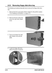
Locate the floppy disk drive cable and power connectors. 2-16 ASUS AW1500-I5 Pull out and detach the right side chassis cover and set aside. 4. Remove the front cover panel. Perform steps #1, #2 and #3 in section "2.5.2 Installing a 5.25 device" on page 2-13. 2. 2.5.3 Removing floppy disk drive tray The following procedures describe how to remove the floppy disk drive tray. 1. Remove the two screws that secure the right side chassis cover. 3.
Locate the floppy disk drive cable and power connectors. 2-16 ASUS AW1500-I5 Pull out and detach the right side chassis cover and set aside. 4. Remove the front cover panel. Perform steps #1, #2 and #3 in section "2.5.2 Installing a 5.25 device" on page 2-13. 2. 2.5.3 Removing floppy disk drive tray The following procedures describe how to remove the floppy disk drive tray. 1. Remove the two screws that secure the right side chassis cover. 3.

AW1500-I5 English Manual
Page 38
When the tray lever is a removable tray for mounting an SCA SCSI hard disk drive. Pull the tray outwards on the tray lever. 2-18 ASUS AW1500-I5 2.6 Installing a Hard Disk Drive The server comes with six externally accessible drive bays. To release the drive bay, follow these steps. 1. In each of the drive bays is pulled down, the tray will eject slightly. Lift the spring lock upwards, then pull the tray lever outwards. 2.
When the tray lever is a removable tray for mounting an SCA SCSI hard disk drive. Pull the tray outwards on the tray lever. 2-18 ASUS AW1500-I5 2.6 Installing a Hard Disk Drive The server comes with six externally accessible drive bays. To release the drive bay, follow these steps. 1. In each of the drive bays is pulled down, the tray will eject slightly. Lift the spring lock upwards, then pull the tray lever outwards. 2.
AW1500-I5 English Manual
Page 40
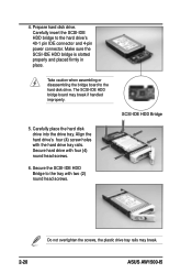
... handled improperly. 5. Prepare hard disk drive. Carefully insert the SCSI-IDE HDD bridge to the hard drive's 40-1 pin IDE connector and 4-pin power connector. ASUS AW1500-I5
... handled improperly. 5. Prepare hard disk drive. Carefully insert the SCSI-IDE HDD bridge to the hard drive's 40-1 pin IDE connector and 4-pin power connector. ASUS AW1500-I5


