
User Manual
Page 2
..., or translated into any warranty. No part of the LGPL Software (with you encounter any problems in this manual, including the products and software described in it shipped to, by downloading it from http://support.asus.com/download; SPECIFICATIONS AND INFORMATION CONTAINED IN THIS MANUAL ARE FURNISHED FOR INFORMATIONAL USE ONLY, AND ARE SUBJECT TO CHANGE AT ANY TIME WITHOUT NOTICE, AND SHOULD...
..., or translated into any warranty. No part of the LGPL Software (with you encounter any problems in this manual, including the products and software described in it shipped to, by downloading it from http://support.asus.com/download; SPECIFICATIONS AND INFORMATION CONTAINED IN THIS MANUAL ARE FURNISHED FOR INFORMATIONAL USE ONLY, AND ARE SUBJECT TO CHANGE AT ANY TIME WITHOUT NOTICE, AND SHOULD...

User Manual
Page 3
... (CPU 1-3 1.4 System memory 1-3 1.4.1 Overview 1-3 1.4.2 Memory configurations 1-4 1.5 Expansion slot 1-6 1.5.1 Installing an expansion card 1-6 1.5.2 Configuring an expansion card 1-6 1.5.3 PCI Express x4 slots 1-6 1.6 Jumpers 1-7 1.7 Connectors 1-9 1.7.1 Rear panel connectors 1-9 1.7.2 Internal connectors 1-10 1.8 Software support 1-16 1.8.1 Installing an operating system 1-16 1.8.2 Support DVD information 1-16 Chapter 2: BIOS information 2.1 Managing and updating your BIOS 2-1 2.1.1 ASUS Update utility 2-1 2.1.2 ASUS EZ Flash 2 2-2 2.1.3 ASUS CrashFree BIOS 3 2-3 2.2 BIOS...
... (CPU 1-3 1.4 System memory 1-3 1.4.1 Overview 1-3 1.4.2 Memory configurations 1-4 1.5 Expansion slot 1-6 1.5.1 Installing an expansion card 1-6 1.5.2 Configuring an expansion card 1-6 1.5.3 PCI Express x4 slots 1-6 1.6 Jumpers 1-7 1.7 Connectors 1-9 1.7.1 Rear panel connectors 1-9 1.7.2 Internal connectors 1-10 1.8 Software support 1-16 1.8.1 Installing an operating system 1-16 1.8.2 Support DVD information 1-16 Chapter 2: BIOS information 2.1 Managing and updating your BIOS 2-1 2.1.1 ASUS Update utility 2-1 2.1.2 ASUS EZ Flash 2 2-2 2.1.3 ASUS CrashFree BIOS 3 2-3 2.2 BIOS...
User Manual
Page 8
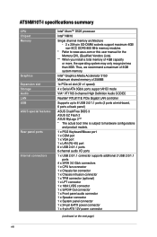
... 3GB. AT5NM10T-I specifications summary CPU Chipset Memory Graphics Expansion slot Storage Audio LAN USB ASUS special features Rear panel ports Internal connectors Intel® Atom™ D525 processor Intel® NM10 Single channel memory architecture - 2 x 204-pin SO-DIMM sockets support maximum 4GB non-ECC DDR3 800 MHz memory modules * Refer to hardware configurations and product models. 1 x PS/2 Keyboard/Mouse port 1 x COM port 1 x VGA port 1 x LAN (RJ-45) port 6 x USB 2.0/1.1 ports 6-channel audio I/O ports 1 x USB 2.0/1.1 connector supports additional 2 USB 2.0/1.1 ports 4 x SATA...
... 3GB. AT5NM10T-I specifications summary CPU Chipset Memory Graphics Expansion slot Storage Audio LAN USB ASUS special features Rear panel ports Internal connectors Intel® Atom™ D525 processor Intel® NM10 Single channel memory architecture - 2 x 204-pin SO-DIMM sockets support maximum 4GB non-ECC DDR3 800 MHz memory modules * Refer to hardware configurations and product models. 1 x PS/2 Keyboard/Mouse port 1 x COM port 1 x VGA port 1 x LAN (RJ-45) port 6 x USB 2.0/1.1 ports 6-channel audio I/O ports 1 x USB 2.0/1.1 connector supports additional 2 USB 2.0/1.1 ports 4 x SATA...

User Manual
Page 12
.... USB device wake-up (3-pin USBPW7-8) 7. Keyboard/mouse power setting (3-pin PS2_USBPW1-6) 9. Speaker connector (4-pin SPEAKER) 1-12 18. Doing so can damage the motherboard. 1.2.2 Layout contents Connectors/Jumpers/Slots/LED Page Connectors/Jumpers/Slots/LED 1. LPT connector (26-1 pin LPT ) 1-16 10. Serial ATA connectors (7-pin SATA3G_1, SATA3G_2, SATA3G_E1, SATA3G_E2) 5. DO NOT overtighten the screws! Clear RTC RAM (3-pin CLRTC) 3. Onboard LED (SB_PWR) 4. DDR3 SO-DIMM sockets 1-3 16. Digital audio connector (4-1 pin SPDIF_OUT) 8. Chassis intrusion...
.... USB device wake-up (3-pin USBPW7-8) 7. Keyboard/mouse power setting (3-pin PS2_USBPW1-6) 9. Speaker connector (4-pin SPEAKER) 1-12 18. Doing so can damage the motherboard. 1.2.2 Layout contents Connectors/Jumpers/Slots/LED Page Connectors/Jumpers/Slots/LED 1. LPT connector (26-1 pin LPT ) 1-16 10. Serial ATA connectors (7-pin SATA3G_1, SATA3G_2, SATA3G_E1, SATA3G_E2) 5. DO NOT overtighten the screws! Clear RTC RAM (3-pin CLRTC) 3. Onboard LED (SB_PWR) 4. DDR3 SO-DIMM sockets 1-3 16. Digital audio connector (4-1 pin SPDIF_OUT) 8. Chassis intrusion...
User Manual
Page 16
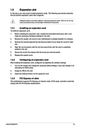
.... 6. Align the card connector with the slot and press firmly until the card is already installed in a chassis). 3. Turn on the slot. 5. Install the software drivers for the card. 2. Failure to do so may need to use . 4. Keep the screw for information on BIOS setup. 2. Replace the system cover. 1.5.2 Configuring an expansion card After installing the expansion card, configure it supports. Assign an IRQ to the chassis with the PCI Express specifications. ASUS AT5NM10T-I 1-6 Before installing the expansion card, read the...
.... 6. Align the card connector with the slot and press firmly until the card is already installed in a chassis). 3. Turn on the slot. 5. Install the software drivers for the card. 2. Failure to do so may need to use . 4. Keep the screw for information on BIOS setup. 2. Replace the system cover. 1.5.2 Configuring an expansion card After installing the expansion card, configure it supports. Assign an IRQ to the chassis with the PCI Express specifications. ASUS AT5NM10T-I 1-6 Before installing the expansion card, read the...

User Manual
Page 18
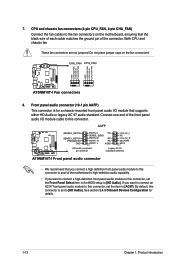
... mouse or using the connected USB devices. USB device wake-up (3-pin USBPW7-8) Set this jumper to pins 2-3 (+5VSB), you can wake up . • The total current consumed must NOT exceed the power supply capability (+5VSB) whether under normal condition or in sleep mode. When you to wake up feature. AT5NM10T-I PS2_USBPW1-6 12 23 +5V +5VSB (Default) AT5NM10T-I 1-8 Set to +5VSB to enable or disable the keyboard/mouse and USB port 1-6 wake-up from S1 sleep mode (CPU stopped, DRAM refreshed...
... mouse or using the connected USB devices. USB device wake-up (3-pin USBPW7-8) Set this jumper to pins 2-3 (+5VSB), you can wake up . • The total current consumed must NOT exceed the power supply capability (+5VSB) whether under normal condition or in sleep mode. When you to wake up feature. AT5NM10T-I PS2_USBPW1-6 12 23 +5V +5VSB (Default) AT5NM10T-I 1-8 Set to +5VSB to enable or disable the keyboard/mouse and USB port 1-6 wake-up from S1 sleep mode (CPU stopped, DRAM refreshed...

User Manual
Page 20
... devices. • This motherboard supports VGA and LVDS display devices. The power supply plugs are uncertain about the minimum power supply requirement for a VGA monitor or other serial devices. 10. com/PowerSupplyCalculator/PSCalculator.aspx?SLanguage=en-us for ATX power supply plugs. USB 2.0 ports 3 and 4. COM port. USB 2.0 ports 5 and 6. In Single Display mode, use , then press the hot keys to switch to use an ATX 12V Specification 2.0‑compliant power supply unit (PSU) with 20-pin and 4-pin power plugs, ensure that device. 9. Otherwise, the system will not boot...
... devices. • This motherboard supports VGA and LVDS display devices. The power supply plugs are uncertain about the minimum power supply requirement for a VGA monitor or other serial devices. 10. com/PowerSupplyCalculator/PSCalculator.aspx?SLanguage=en-us for ATX power supply plugs. USB 2.0 ports 3 and 4. COM port. USB 2.0 ports 5 and 6. In Single Display mode, use , then press the hot keys to switch to use an ATX 12V Specification 2.0‑compliant power supply unit (PSU) with 20-pin and 4-pin power plugs, ensure that device. 9. Otherwise, the system will not boot...
User Manual
Page 23
... connector, set to the fan connectors on the fan connectors! Both CPU and chassis fan These fan connectors are not jumpers! If you want to connect an AC'97 front panel audio module to this connector. 7. CHA_FAN CPU_FAN AT5NM10T-I GND CHA FAN PWR CHA FAN IN CHA FAN PWM GND CPU FAN PWR CPU FAN IN CPU FAN PWM AT5NM10T-I /O module cable to [HD Audio]. CPU and chassis fan connectors (4-pin CPU_FAN, 4-pin CHA_FAN) Connect the fan cables to [HD Audio]. Do not place jumper caps on the motherboard, ensuring that supports...
... connector, set to the fan connectors on the fan connectors! Both CPU and chassis fan These fan connectors are not jumpers! If you want to connect an AC'97 front panel audio module to this connector. 7. CHA_FAN CPU_FAN AT5NM10T-I GND CHA FAN PWR CHA FAN IN CHA FAN PWM GND CPU FAN PWR CPU FAN IN CPU FAN PWM AT5NM10T-I /O module cable to [HD Audio]. CPU and chassis fan connectors (4-pin CPU_FAN, 4-pin CHA_FAN) Connect the fan cables to [HD Audio]. Do not place jumper caps on the motherboard, ensuring that supports...
User Manual
Page 26
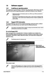
... ASUS motherboard. 1.8 Software support 1.8.1 Installing an operating system This motherboard supports Windows® XP/Vista/7 Operating Systems (OS). Visit the ASUS website at any time without notice. The following screen is enabled in your hardware. • Motherboard settings and hardware options vary. To run the DVD. Always install the latest OS version and corresponding updates to the optical drive. If Autorun is for updates. Click Drivers, Utilities, Make Disk, Manual, and Contact tabs to display...
... ASUS motherboard. 1.8 Software support 1.8.1 Installing an operating system This motherboard supports Windows® XP/Vista/7 Operating Systems (OS). Visit the ASUS website at any time without notice. The following screen is enabled in your hardware. • Motherboard settings and hardware options vary. To run the DVD. Always install the latest OS version and corresponding updates to the optical drive. If Autorun is for updates. Click Drivers, Utilities, Make Disk, Manual, and Contact tabs to display...
User Manual
Page 27
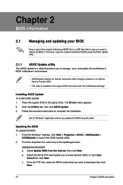
... download then click Next. 2-1 Chapter 2: BIOS information The Drivers menu appears. 2. Follow the onscreen instructions to launch the ASUS Update utility. 2. From the dropdown list, select any of the original motherboard BIOS file to a USB flash disk in case you need to restore the BIOS in the optical drive. Copy the original motherboard BIOS using this utility. Click the Utilities tab, then click ASUS Update. 3. From the Windows® desktop, click Start > Programs > ASUS > ASUSUpdate > ASUSUpdate to complete the installation...
... download then click Next. 2-1 Chapter 2: BIOS information The Drivers menu appears. 2. Follow the onscreen instructions to launch the ASUS Update utility. 2. From the dropdown list, select any of the original motherboard BIOS file to a USB flash disk in case you need to restore the BIOS in the optical drive. Copy the original motherboard BIOS using this utility. Click the Utilities tab, then click ASUS Update. 3. From the Windows® desktop, click Start > Programs > ASUS > ASUSUpdate > ASUSUpdate to complete the installation...

User Manual
Page 28
.... 3. ASUS AT5NM10T-I VER: 0306 (H:00 B:02) DATE: 02/23/2011 Update ROM BOARD: Unknown VER: Unknown DATE: Unknown PATH: A:\ A: Note [Enter] Select or Load [Up/Down/Home/End] Move [Tab] Switch [B] Backup [V] Drive Info [ESC] Exit 2. To update the BIOS using an OS‑based utility. Insert the USB flash disk that contains the latest BIOS file to complete the updating process. 2.1.2 ASUS EZ Flash 2 The ASUS EZ Flash 2 feature allows you start using this utility, download...
.... 3. ASUS AT5NM10T-I VER: 0306 (H:00 B:02) DATE: 02/23/2011 Update ROM BOARD: Unknown VER: Unknown DATE: Unknown PATH: A:\ A: Note [Enter] Select or Load [Up/Down/Home/End] Move [Tab] Switch [B] Backup [V] Drive Info [ESC] Exit 2. To update the BIOS using an OS‑based utility. Insert the USB flash disk that contains the latest BIOS file to complete the updating process. 2.1.2 ASUS EZ Flash 2 The ASUS EZ Flash 2 feature allows you start using this utility, download...
User Manual
Page 29
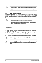
... motherboard support DVD or a USB flash drive that contains the BIOS file to the USB port. 3. Ensure to load the BIOS default settings to section 2.8 Exit menu for the BIOS file. You can cause system boot failure! DO NOT shut down or reset the system while updating the BIOS to prevent system boot failure! 2.1.3 ASUS CrashFree BIOS 3 The ASUS CrashFree BIOS 3 is an auto recovery tool that allows you to the optical drive or the removable device that contains the updated BIOS file. • Before using this utility...
... motherboard support DVD or a USB flash drive that contains the BIOS file to the USB port. 3. Ensure to load the BIOS default settings to section 2.8 Exit menu for the BIOS file. You can cause system boot failure! DO NOT shut down or reset the system while updating the BIOS to prevent system boot failure! 2.1.3 ASUS CrashFree BIOS 3 The ASUS CrashFree BIOS 3 is an auto recovery tool that allows you to the optical drive or the removable device that contains the updated BIOS file. • Before using this utility...

User Manual
Page 31
... the device supports this mode, and if the device was not previously formatted with LBA mode disabled. These items show Not Detected if no Serial ATA device is either a ZIP, LS-120, or MO drive. Select Screen Select Item +- There is a separate sub-menu for each SATA device. These values are specifically configuring a CD-ROM drive. Type [Auto] Selects the type of the appropriate SATA device type. Setting to Auto allows automatic selection of SATA drive. Main Advanced AT5NM10T-I BIOS Setup Power Boot...
... the device supports this mode, and if the device was not previously formatted with LBA mode disabled. These items show Not Detected if no Serial ATA device is either a ZIP, LS-120, or MO drive. Select Screen Select Item +- There is a separate sub-menu for each SATA device. These values are specifically configuring a CD-ROM drive. Type [Auto] Selects the type of the appropriate SATA device type. Setting to Auto allows automatic selection of SATA drive. Main Advanced AT5NM10T-I BIOS Setup Power Boot...

User Manual
Page 32
...change the configurations for the Serial ATA connectors supported by the Southbridge chip. Configuration options: [Disabled] [Enabled] 2.3.4 Storage Configuration The items in this menu allow you to the device occurs multiple sectors at a time. Configuration options: [IDE] [AHCI] [Disabled] SATA Run Mode Configuration [Compatible] Sets the SATA run mode configuration. The BIOS automatically detects the items in this menu. ASUS AT5NM10T-I 2-6 Block (Multi-sector Transfer) Mode [Auto] Enables or disables data multi-sectors transfers. Configuration options: [Auto] SMART Monitoring...
...change the configurations for the Serial ATA connectors supported by the Southbridge chip. Configuration options: [Disabled] [Enabled] 2.3.4 Storage Configuration The items in this menu allow you to the device occurs multiple sectors at a time. Configuration options: [IDE] [AHCI] [Disabled] SATA Run Mode Configuration [Compatible] Sets the SATA run mode configuration. The BIOS automatically detects the items in this menu. ASUS AT5NM10T-I 2-6 Block (Multi-sector Transfer) Mode [Auto] Enables or disables data multi-sectors transfers. Configuration options: [Auto] SMART Monitoring...

User Manual
Page 33
.... Configuration options: [Disabled] [Enabled] Execute-Disable Bit Capability [Enabled] Allows you to determine whether to enable or disable the No-Execution Page Protection Technology. Main Advanced AT5NM10T-I BIOS Setup Power Boot Tools Exit CPU Configuration Chipset Onboard Devices Configuration USB Configuration PCIPnP Version 0306 Configure CPU. 2.4.1 CPU Configuration The items in this item to [Disabled] forces the XD feature flag to always return to malfunction. Configuration options: [IGD] [PCIE/IGD] Internal Graphics Mode Select [Enabled, 8MB] Sets the IGD graphics mode.
.... Configuration options: [Disabled] [Enabled] Execute-Disable Bit Capability [Enabled] Allows you to determine whether to enable or disable the No-Execution Page Protection Technology. Main Advanced AT5NM10T-I BIOS Setup Power Boot Tools Exit CPU Configuration Chipset Onboard Devices Configuration USB Configuration PCIPnP Version 0306 Configure CPU. 2.4.1 CPU Configuration The items in this item to [Disabled] forces the XD feature flag to always return to malfunction. Configuration options: [IGD] [PCIE/IGD] Internal Graphics Mode Select [Enabled, 8MB] Sets the IGD graphics mode.

User Manual
Page 34
... ASUS AT5NM10T-I 2-8 Configuration options: [Disabled] [Enabled] Front Panel Select [HD Audio] Configuration options: [AC97] [HD Audio] OnBoard LAN Controller [Enabled] Configuration options: [Disabled] [Enabled] OnBoard LAN Boot ROM [Disabled] Configuration options: [Disabled] [Enabled] JMicron 36x ATA Controller [IDE Mode] Allows you to select the DVMT mode. Configuration options: [SSP] [EPP] [ECP] [EPP + ECP] ECP Mode DMA Channel [DMA3] Appears only when the Parallel Port Mode is set the Parallel Port ECP DMA. Configuration options: [DVMT Mode] [Fixed Mode] DVMT/FIXED Memory [Maxiimum...
... ASUS AT5NM10T-I 2-8 Configuration options: [Disabled] [Enabled] Front Panel Select [HD Audio] Configuration options: [AC97] [HD Audio] OnBoard LAN Controller [Enabled] Configuration options: [Disabled] [Enabled] OnBoard LAN Boot ROM [Disabled] Configuration options: [Disabled] [Enabled] JMicron 36x ATA Controller [IDE Mode] Allows you to select the DVMT mode. Configuration options: [SSP] [EPP] [ECP] [EPP + ECP] ECP Mode DMA Channel [DMA3] Appears only when the Parallel Port Mode is set the Parallel Port ECP DMA. Configuration options: [DVMT Mode] [Fixed Mode] DVMT/FIXED Memory [Maxiimum...

User Manual
Page 35
...] [Enabled] USB 2.0 Controller [Enabled] Allows you to change the USB-related features. Configuration options: [No] [Yes] 2-9 Chapter 2: BIOS information When this item is plugged. 2.4.5 PCIPnP The PCI PnP menu items allow you to enable or disable support for Legacy USB storage devices, including USB flash drives and USB hard drives. 2.4.4 USB Configuration The items in this menu allows you install a Plug and Play operating system, the operating system configures the Plug and Play devices not required for boot. The Module Version and USB Devices Enabled items show the auto...
...] [Enabled] USB 2.0 Controller [Enabled] Allows you to change the USB-related features. Configuration options: [No] [Yes] 2-9 Chapter 2: BIOS information When this item is plugged. 2.4.5 PCIPnP The PCI PnP menu items allow you to enable or disable support for Legacy USB storage devices, including USB flash drives and USB hard drives. 2.4.4 USB Configuration The items in this menu allows you install a Plug and Play operating system, the operating system configures the Plug and Play devices not required for boot. The Module Version and USB Devices Enabled items show the auto...

User Manual
Page 36
...] [Enabled] ASUS AT5NM10T-I BIOS Setup Power Boot Tools Exit Suspend Mode ACPI 2.0 Support ACPI APIC Support Control EuP [S3 only] [Disabled] [Enabled] [Disabled] APM Configuration Hardware Monitor Version 0306 Select the ACPI state used for Advanced Configuration and Power Interface (ACPI) 2.0 specifications. Main Advanced AT5NM10T-I 2-10 When set values. Configuration option: [S3 Only] [S3 Only] - Enables the system to enter the ACPI S3 (Suspend to generate a wake event. Configuration options: [Disabled] [Enabled] 2.5.4 Control EuP [Disabled] Enables or disables the...
...] [Enabled] ASUS AT5NM10T-I BIOS Setup Power Boot Tools Exit Suspend Mode ACPI 2.0 Support ACPI APIC Support Control EuP [S3 only] [Disabled] [Enabled] [Disabled] APM Configuration Hardware Monitor Version 0306 Select the ACPI state used for Advanced Configuration and Power Interface (ACPI) 2.0 specifications. Main Advanced AT5NM10T-I 2-10 When set values. Configuration option: [S3 Only] [S3 Only] - Enables the system to enter the ACPI S3 (Suspend to generate a wake event. Configuration options: [Disabled] [Enabled] 2.5.4 Control EuP [Disabled] Enables or disables the...

User Manual
Page 38
... available devices. Configuration options: [Removable Dev.] [Hard Drive] [ATAPI CD-ROM] [Disabled] • To select the boot device during system startup, press when ASUS Logo appears. • To access Windows® OS in the system. When set to [Disabled], BIOS performs all the POST items. Configuration options: [Disabled] [Enabled] Full Screen Logo [Enabled] This allows you to display the sub-menu. The number of device items that appears on the screen depends on the number of devices installed in Safe Mode...
... available devices. Configuration options: [Removable Dev.] [Hard Drive] [ATAPI CD-ROM] [Disabled] • To select the boot device during system startup, press when ASUS Logo appears. • To access Windows® OS in the system. When set to [Disabled], BIOS performs all the POST items. Configuration options: [Disabled] [Enabled] Full Screen Logo [Enabled] This allows you to display the sub-menu. The number of device items that appears on the screen depends on the number of devices installed in Safe Mode...

User Manual
Page 40
... ASUS AT5NM10T-I BIOS Setup Power Boot Tools Exit Options Exit & Save Changes Exit & Discard Changes Discard Changes Load Setup Defaults Exit Version 0306 ExEixtitsyssytsetmemsesteutpup afatfetrersasvaivnigngthtehe chcahnagnegse.s. F1F010kekyeycacnanbebeusuesded fofrorthtihsisopoepreartaitoino.n. The message Password Installed appears after you set your choice. To change the user password, follow the same steps in setting a user password. Main Advanced AT5NM10T-I BIOS Setup Power Boot Tools Exit ASUS EZ Flash 2 Version 0306 Press ENTER to display the sub-menu. menu...
... ASUS AT5NM10T-I BIOS Setup Power Boot Tools Exit Options Exit & Save Changes Exit & Discard Changes Discard Changes Load Setup Defaults Exit Version 0306 ExEixtitsyssytsetmemsesteutpup afatfetrersasvaivnigngthtehe chcahnagnegse.s. F1F010kekyeycacnanbebeusuesded fofrorthtihsisopoepreartaitoino.n. The message Password Installed appears after you set your choice. To change the user password, follow the same steps in setting a user password. Main Advanced AT5NM10T-I BIOS Setup Power Boot Tools Exit ASUS EZ Flash 2 Version 0306 Press ENTER to display the sub-menu. menu...


