
User Manual
Page 1
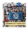
AT3N7A-I Motherboard
AT3N7A-I Motherboard
User Manual
Page 3
Contents Notices...v Safety information vi About this guide vii AT3N7A-I specifications summary viii Chapter 1: Product introduction 1-1 1.1 Before you proceed 1-1 1.2 Motherboard overview 1-2 1.2.1 Motherboard layout 1-2 1.2.2 Layout contents 1-2 1.3 Central Processing Unit (CPU 1-3 1.4 System memory 1-3 1.4.1 Overview... 2-1 2.1 Managing and updating your BIOS 2-1 2.1.1 ASUS Update utility 2-1 2.1.2 ASUS EZ Flash 2 2-2 2.1.3 ASUS CrashFree BIOS 2-3 2.2 BIOS setup program 2-4 2.3 Main menu 2-4 2.3.1 System Time 2-5 2.3.2 System Date 2-5 2.3.3 SATA 1~3, ESATA ...
Contents Notices...v Safety information vi About this guide vii AT3N7A-I specifications summary viii Chapter 1: Product introduction 1-1 1.1 Before you proceed 1-1 1.2 Motherboard overview 1-2 1.2.1 Motherboard layout 1-2 1.2.2 Layout contents 1-2 1.3 Central Processing Unit (CPU 1-3 1.4 System memory 1-3 1.4.1 Overview... 2-1 2.1 Managing and updating your BIOS 2-1 2.1.1 ASUS Update utility 2-1 2.1.2 ASUS EZ Flash 2 2-2 2.1.3 ASUS CrashFree BIOS 2-3 2.2 BIOS setup program 2-4 2.3 Main menu 2-4 2.3.1 System Time 2-5 2.3.2 System Date 2-5 2.3.3 SATA 1~3, ESATA ...
User Manual
Page 5
... Part 15 of the crossed out wheeled bin indicates that the battery should not be placed in our products at ASUS REACH website at http://green.asus.com/english/REACH.htm. This class B digital apparatus complies with manufacturer's instructions, may cause undesired operation. This ... must accept any interference received including interference that interference will not occur in municipal waste. If this equipment. DO NOT throw the motherboard in municipal waste. This equipment has been tested and found to which can radiate radio frequency energy and, if not installed and ...
... Part 15 of the crossed out wheeled bin indicates that the battery should not be placed in our products at ASUS REACH website at http://green.asus.com/english/REACH.htm. This class B digital apparatus complies with manufacturer's instructions, may cause undesired operation. This ... must accept any interference received including interference that interference will not occur in municipal waste. If this equipment. DO NOT throw the motherboard in municipal waste. This equipment has been tested and found to which can radiate radio frequency energy and, if not installed and ...

User Manual
Page 6
... • Avoid dust, humidity, and temperature extremes. Do not place the product in fire. Operation safety • Before installing the motherboard and adding devices on a stable surface. • If you are not damaged. These devices could explode and release harmful substances into the... to a hazardous material collection point. • Never replace the battery with the product, contact a qualified service technician or your motherboard) and is an optional component (may or may become wet. Contact a qualified service technician or your regular household waste. INVISIBLE ...
... • Avoid dust, humidity, and temperature extremes. Do not place the product in fire. Operation safety • Before installing the motherboard and adding devices on a stable surface. • If you are not damaged. These devices could explode and release harmful substances into the... to a hazardous material collection point. • Never replace the battery with the product, contact a qualified service technician or your motherboard) and is an optional component (may or may become wet. Contact a qualified service technician or your regular household waste. INVISIBLE ...
User Manual
Page 7
...to complete a task. Refer to select. ASUS websites The ASUS website provides updated information on ASUS hardware and software products. Conventions used throughout this guide To ensure that you perform certain tasks properly, take note of the motherboard and the new technology it supports. &#...optional documentation, such as warranty flyers, that you need when installing and configuring the motherboard. Typography Bold text Italics ++ Indicates a menu or an item to the ASUS contact information. 2. Used to change system settings through the BIOS Setup menus. IMPORTANT:...
...to complete a task. Refer to select. ASUS websites The ASUS website provides updated information on ASUS hardware and software products. Conventions used throughout this guide To ensure that you perform certain tasks properly, take note of the motherboard and the new technology it supports. &#...optional documentation, such as warranty flyers, that you need when installing and configuring the motherboard. Typography Bold text Italics ++ Indicates a menu or an item to the ASUS contact information. 2. Used to change system settings through the BIOS Setup menus. IMPORTANT:...

User Manual
Page 10
...following precautions before you install motherboard components or change any motherboard settings. • Unplug the power cord from the power supply. Before you for the list of the onboard LED. Refer to the motherboard, peripherals, or components. ASUS AT3N7A-I motherboard! Failure to do so ...may cause severe damage to page ix for buying an ASUS® AT3N7A-I 1-1 Onboard LED The motherboard comes with the component. • Before you must shut...
...following precautions before you install motherboard components or change any motherboard settings. • Unplug the power cord from the power supply. Before you for the list of the onboard LED. Refer to the motherboard, peripherals, or components. ASUS AT3N7A-I motherboard! Failure to do so ...may cause severe damage to page ix for buying an ASUS® AT3N7A-I 1-1 Onboard LED The motherboard comes with the component. • Before you must shut...
User Manual
Page 11
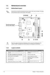
...Atom 330 processor 5. DDR2 DIMM slots 6. PCI slot 1-15 12. 1.2 1.2.1 Motherboard overview Motherboard layout Ensure that you install the motherboard into the holes indicated by circles to secure the motherboard to the rear part of the chassis. Clear RTC RAM (3-pin CLRTC) 1-3 10...Front panel audio connector (10-1 pin AAFP) Page 1-13 1-1 1-8 1-12 1-7 1-14 1-2 Chapter 1: Product introduction Doing so can damage the motherboard. 1.2.2 Layout contents Connectors/Jumpers/Slots/LED 1. CPU, power, and chassis fan connectors (3-pin CPU_FAN, 3-pin PWR_FAN, 3-pin CHA_FAN) 3. System ...
...Atom 330 processor 5. DDR2 DIMM slots 6. PCI slot 1-15 12. 1.2 1.2.1 Motherboard overview Motherboard layout Ensure that you install the motherboard into the holes indicated by circles to secure the motherboard to the rear part of the chassis. Clear RTC RAM (3-pin CLRTC) 1-3 10...Front panel audio connector (10-1 pin AAFP) Page 1-13 1-1 1-8 1-12 1-7 1-14 1-2 Chapter 1: Product introduction Doing so can damage the motherboard. 1.2.2 Layout contents Connectors/Jumpers/Slots/LED 1. CPU, power, and chassis fan connectors (3-pin CPU_FAN, 3-pin PWR_FAN, 3-pin CHA_FAN) 3. System ...
User Manual
Page 12
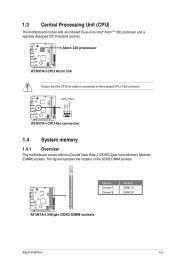
Ensure that the CPU fan cable is connected to the onboard CPU_Fan connector. 1.4 System memory 1.4.1 Overview The motherboard comes with an onboard Dual-Core Intel® Atom™ 330 processor and a specially designed CPU heatsink and fan. The figure illustrates the location of the DDR2 DIMM sockets: Channel Channel A Channel B Sockets DIMM_A1 DIMM_B1 ASUS AT3N7A-I 1-3 1.3 Central Processing Unit (CPU) The motherboard comes with two Double Data Rate 2 (DDR2) Dual Inline Memory Modules (DIMM) sockets.
Ensure that the CPU fan cable is connected to the onboard CPU_Fan connector. 1.4 System memory 1.4.1 Overview The motherboard comes with an onboard Dual-Core Intel® Atom™ 330 processor and a specially designed CPU heatsink and fan. The figure illustrates the location of the DDR2 DIMM sockets: Channel Channel A Channel B Sockets DIMM_A1 DIMM_B1 ASUS AT3N7A-I 1-3 1.3 Central Processing Unit (CPU) The motherboard comes with two Double Data Rate 2 (DDR2) Dual Inline Memory Modules (DIMM) sockets.
User Manual
Page 13
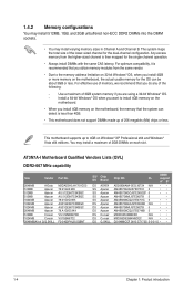
... made up of the following: - The system maps the total size of 3GB system memory if you install 4GB or more memory on the motherboard, the memory that the system can be about 3GB or less. Use a maximum of the lower-sized channel for the single-channel operation....sizes in Channel A and Channel B. Any excess memory from the higher-sized channel is recommended that you want to 4GB on each slot. AT3N7A-I Motherboard Qualified Vendors Lists (QVL) DDR2-667 MHz capability Size Vendor Part No. 2048MB A-Data 512MB Apacer 512MB Apacer 512MB Apacer 1024MB Apacer 1024MB ...
... made up of the following: - The system maps the total size of 3GB system memory if you install 4GB or more memory on the motherboard, the memory that the system can be about 3GB or less. Use a maximum of the lower-sized channel for the single-channel operation....sizes in Channel A and Channel B. Any excess memory from the higher-sized channel is recommended that you want to 4GB on each slot. AT3N7A-I Motherboard Qualified Vendors Lists (QVL) DDR2-667 MHz capability Size Vendor Part No. 2048MB A-Data 512MB Apacer 512MB Apacer 512MB Apacer 1024MB Apacer 1024MB ...
User Manual
Page 16
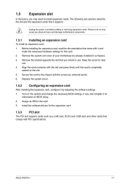
...PCI slot The PCI slot supports cards such as a LAN card, SCSI card, USB card, and other cards that you physical injury and damage motherboard components. 1.5.1 Installing an expansion card To install an expansion card: 1. Secure the card to the chassis with it supports. See Chapter 2 for... Install the software drivers for later use . ASUS AT3N7A-I 1-7 Failure to do so may need to install expansion cards. Align the card connector with PCI specifications. Assign an IRQ to use . 4. Remove the system unit cover (if your motherboard is completely seated on the slot. 5. The...
...PCI slot The PCI slot supports cards such as a LAN card, SCSI card, USB card, and other cards that you physical injury and damage motherboard components. 1.5.1 Installing an expansion card To install an expansion card: 1. Secure the card to the chassis with it supports. See Chapter 2 for... Install the software drivers for later use . ASUS AT3N7A-I 1-7 Failure to do so may need to install expansion cards. Align the card connector with PCI specifications. Assign an IRQ to use . 4. Remove the system unit cover (if your motherboard is completely seated on the slot. 5. The...
User Manual
Page 21
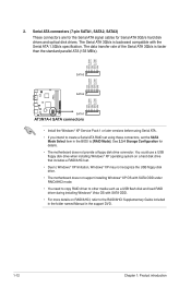
...ATA 1.5Gb/s specification. Serial ATA connectors (7-pin SATA1, SATA2, SATA3) These connectors are for the Serial ATA signal cables for details. • The motherboard does not provide a floppy disk drive connector. The Serial ATA 3Gb/s is faster than the standard parallel ATA (133 MB/s). • Install the Windows..., set . • Due to Windows® XP limitation, Windows® XP may not recognize the USB floppy disk drive. • The motherboard does not support installing Windows® XP OS with SATA ODD under RAID/AHCI mode. • You need to copy RAID driver to the RAID...
...ATA 1.5Gb/s specification. Serial ATA connectors (7-pin SATA1, SATA2, SATA3) These connectors are for the Serial ATA signal cables for details. • The motherboard does not provide a floppy disk drive connector. The Serial ATA 3Gb/s is faster than the standard parallel ATA (133 MB/s). • Install the Windows..., set . • Due to Windows® XP limitation, Windows® XP may not recognize the USB floppy disk drive. • The motherboard does not support installing Windows® XP OS with SATA ODD under RAID/AHCI mode. • You need to copy RAID driver to the RAID...
User Manual
Page 22
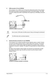
... detection sensor or switch. Doing so will damage the motherboard! The signal is purchased separately. 4. By default, the pin labeled "Chassis Signal" and "Ground" are shorted with USB 2.0 specification that supports up to this connector when a chassis component is for a USB 2.0 port. ASUS AT3N7A-I 1-13 The chassis intrusion sensor or switch sends a high...
... detection sensor or switch. Doing so will damage the motherboard! The signal is purchased separately. 4. By default, the pin labeled "Chassis Signal" and "Ground" are shorted with USB 2.0 specification that supports up to this connector when a chassis component is for a USB 2.0 port. ASUS AT3N7A-I 1-13 The chassis intrusion sensor or switch sends a high...
User Manual
Page 23
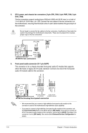
...CPU_FAN, 3-pin PWR_FAN, 3-pin CHA_FAN) The fan connectors support cooling fans of 350 mA~2000 mA (24 W max.) or a total of the motherboard's high-definition audio capability. • If you want to connect a high-definition front panel audio module to this connector to [AC97]. Insufficient air ...flow inside the system may damage the motherboard components. Front panel audio connector (10-1 pin AAFP) This connector is set the Front Panel Select item in the BIOS setup to [HD...
...CPU_FAN, 3-pin PWR_FAN, 3-pin CHA_FAN) The fan connectors support cooling fans of 350 mA~2000 mA (24 W max.) or a total of the motherboard's high-definition audio capability. • If you want to connect a high-definition front panel audio module to this connector to [AC97]. Insufficient air ...flow inside the system may damage the motherboard components. Front panel audio connector (10-1 pin AAFP) This connector is set the Front Panel Select item in the BIOS setup to [HD...
User Manual
Page 25
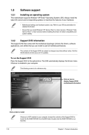
... is for updates. To run the DVD. 1-16 Chapter 1: Product introduction Click an icon to display Support DVD/ motherboard information Click an item to change at www.asus.com for reference only. The DVD automatically displays the Drivers menu if Autorun is enabled in your hardware. •...; Motherboard settings and hardware options vary. The contents of the Support DVD to the optical drive. Double-click the ASSETUP...
... is for updates. To run the DVD. 1-16 Chapter 1: Product introduction Click an icon to display Support DVD/ motherboard information Click an item to change at www.asus.com for reference only. The DVD automatically displays the Drivers menu if Autorun is enabled in your hardware. •...; Motherboard settings and hardware options vary. The contents of the Support DVD to the optical drive. Double-click the ASSETUP...
User Manual
Page 26
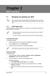
Follow the onscreen instructions to launch the ASUS Update utility. 2. ASUS AT3N7A-I 2-1 Chapter 2 BIOS information 2.1 Managing and updating your BIOS Save a copy of the updating process: Updating from the Internet, then click Next. Quit all... either through a network or an Internet Service Provider (ISP). • This utility is a utility that comes with the motherboard package. Installing ASUS Update To install ASUS Update: 1. Click the Utilities tab, then click ASUS Update. 3. From the FTP site, select the BIOS version that you to manage, save, and update the...
Follow the onscreen instructions to launch the ASUS Update utility. 2. ASUS AT3N7A-I 2-1 Chapter 2 BIOS information 2.1 Managing and updating your BIOS Save a copy of the updating process: Updating from the Internet, then click Next. Quit all... either through a network or an Internet Service Provider (ISP). • This utility is a utility that comes with the motherboard package. Installing ASUS Update To install ASUS Update: 1. Click the Utilities tab, then click ASUS Update. 3. From the FTP site, select the BIOS version that you to manage, save, and update the...
User Manual
Page 28
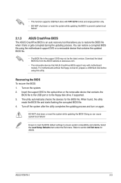
...utility reads the BIOS file and starts flashing the corrupted BIOS file. 4. Doing so can restore a corrupted BIOS file using this utility. ASUS AT3N7A-I 2-3 Turn on again. The utility automatically checks the devices for details. Ensure to load the BIOS default settings to section 2.8 Exit menu...utility completes the updating process and turn on the system. 2. • This function supports USB flash disks with motherboard models. You can cause system boot failure! Recovering the BIOS To recover the BIOS: 1. Refer to ensure system compatibility and stability.
...utility reads the BIOS file and starts flashing the corrupted BIOS file. 4. Doing so can restore a corrupted BIOS file using this utility. ASUS AT3N7A-I 2-3 Turn on again. The utility automatically checks the devices for details. Ensure to load the BIOS default settings to section 2.8 Exit menu...utility completes the updating process and turn on the system. 2. • This function supports USB flash disks with motherboard models. You can cause system boot failure! Recovering the BIOS To recover the BIOS: 1. Refer to ensure system compatibility and stability.
User Manual
Page 29
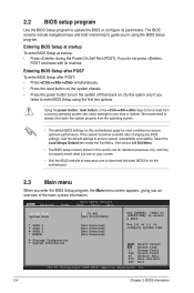
...We recommend to always shut down the system properly from a running operating system can cause damage to your screen. • Visit the ASUS website at startup: • Press during the Power-On Self Test (POST). Storage Configuration System Information Select Screen Select Item +- If...Copyright 1985-2009, American Megatrends, Inc. 2-4 Chapter 2: BIOS information If you failed to download the latest BIOS file for this motherboard apply for this motherboard. 2.3 Main menu When you enter the BIOS Setup program, the Main menu screen appears, giving you an overview of the ...
...We recommend to always shut down the system properly from a running operating system can cause damage to your screen. • Visit the ASUS website at startup: • Press during the Power-On Self Test (POST). Storage Configuration System Information Select Screen Select Item +- If...Copyright 1985-2009, American Megatrends, Inc. 2-4 Chapter 2: BIOS information If you failed to download the latest BIOS file for this motherboard apply for this motherboard. 2.3 Main menu When you enter the BIOS Setup program, the Main menu screen appears, giving you an overview of the ...
User Manual
Page 36
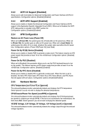
... into either off state after an AC power loss. This feature requires an ATX power supply that provides at least 1A on the +5VSB lead. ASUS AT3N7A-I 2-11 Configuration options: [Disabled] [Enabled] 2.5.3 ACPI APIC Support [Enabled] Allows you do not wish to display the detected speed. Configuration options: [Disabled] [Enabled] Power On... detects and displays the CPU/chassis/power fan speeds in the Application-Specific Integrated Circuit (ASIC). Select Ignored if you do not wish to the motherboard, the field shows N/A.
... into either off state after an AC power loss. This feature requires an ATX power supply that provides at least 1A on the +5VSB lead. ASUS AT3N7A-I 2-11 Configuration options: [Disabled] [Enabled] 2.5.3 ACPI APIC Support [Enabled] Allows you do not wish to display the detected speed. Configuration options: [Disabled] [Enabled] Power On... detects and displays the CPU/chassis/power fan speeds in the Application-Specific Integrated Circuit (ASIC). Select Ignored if you do not wish to the motherboard, the field shows N/A.


