
AT3IONT-I Series user's manual
Page 1
Motherboard AT3IONT-I DELUXE AT3IONT-I
Motherboard AT3IONT-I DELUXE AT3IONT-I

AT3IONT-I Series user's manual
Page 2
...the full corresponding source code we can coordinate the terms and cost of alteration is authorized in it from http://support.asus.com/download; ASUS ASSUMES NO RESPONSIBILITY OR LIABILITY FOR ANY ERRORS OR INACCURACIES THAT MAY APPEAR IN THIS MANUAL, INCLUDING THE PRODUCTS AND ...OR IMPLIED, INCLUDING BUT NOT LIMITED TO THE IMPLIED WARRANTIES OR CONDITIONS OF MERCHANTABILITY OR FITNESS FOR A PARTICULAR PURPOSE. IN NO EVENT SHALL ASUS, ITS DIRECTORS, OFFICERS, EMPLOYEES OR AGENTS BE LIABLE FOR ANY INDIRECT, SPECIAL, INCIDENTAL, OR CONSEQUENTIAL DAMAGES (INCLUDING DAMAGES FOR LOSS OF ...
...the full corresponding source code we can coordinate the terms and cost of alteration is authorized in it from http://support.asus.com/download; ASUS ASSUMES NO RESPONSIBILITY OR LIABILITY FOR ANY ERRORS OR INACCURACIES THAT MAY APPEAR IN THIS MANUAL, INCLUDING THE PRODUCTS AND ...OR IMPLIED, INCLUDING BUT NOT LIMITED TO THE IMPLIED WARRANTIES OR CONDITIONS OF MERCHANTABILITY OR FITNESS FOR A PARTICULAR PURPOSE. IN NO EVENT SHALL ASUS, ITS DIRECTORS, OFFICERS, EMPLOYEES OR AGENTS BE LIABLE FOR ANY INDIRECT, SPECIAL, INCIDENTAL, OR CONSEQUENTIAL DAMAGES (INCLUDING DAMAGES FOR LOSS OF ...
AT3IONT-I Series user's manual
Page 3
Contents Notices...v Safety information vi About this guide vi AT3IONT-I Series specifications summary viii Chapter 1: Product introduction 1.1 Before you proceed 1-1 1.2 Motherboard overview 1-2 1.2.1 Motherboard layout 1-2 1.2.2 Layout contents 1-2 1.3 Central Processing Unit (CPU ... 1-8 1.7.1 Rear panel connectors 1-8 1.7.2 Internal connectors 1-11 1.8 Software support 1-16 1.8.1 Installing an operating system 1-16 1.8.2 Support DVD information 1-16 1.8.3 ASUS VideoSecurity 1-17 1.8.4 ASUS Home Theater Gate 1-19 Chapter 2: BIOS information 2.1 Managing and updating your BIOS...
Contents Notices...v Safety information vi About this guide vi AT3IONT-I Series specifications summary viii Chapter 1: Product introduction 1.1 Before you proceed 1-1 1.2 Motherboard overview 1-2 1.2.1 Motherboard layout 1-2 1.2.2 Layout contents 1-2 1.3 Central Processing Unit (CPU ... 1-8 1.7.1 Rear panel connectors 1-8 1.7.2 Internal connectors 1-11 1.8 Software support 1-16 1.8.1 Installing an operating system 1-16 1.8.2 Support DVD information 1-16 1.8.3 ASUS VideoSecurity 1-17 1.8.4 ASUS Home Theater Gate 1-19 Chapter 2: BIOS information 2.1 Managing and updating your BIOS...

AT3IONT-I Series user's manual
Page 4
... EuP [Disabled 2-12 2.5.5 APM Configuration 2-12 2.5.6 Hardware Monitor 2-12 2.6 Boot menu 2-13 2.6.1 Boot Device Priority 2-13 2.6.2 Boot Settings Configuration 2-13 2.6.3 Security 2-14 2.7 Tools menu 2-15 2.7.1 ASUS EZ Flash 2 2-15 2.7.2 Express Gate [Auto 2-16 2.7.3 AI NET 2 2-16 2.8 Exit menu 2-16 iv
... EuP [Disabled 2-12 2.5.5 APM Configuration 2-12 2.5.6 Hardware Monitor 2-12 2.6 Boot menu 2-13 2.6.1 Boot Device Priority 2-13 2.6.2 Boot Settings Configuration 2-13 2.6.3 Security 2-14 2.7 Tools menu 2-15 2.7.1 ASUS EZ Flash 2 2-15 2.7.2 Express Gate [Auto 2-16 2.7.3 AI NET 2 2-16 2.8 Exit menu 2-16 iv

AT3IONT-I Series user's manual
Page 5
... battery should not be determined by the party responsible for help. This equipment generates, uses and can be placed in our products at ASUS REACH website at http://csr.asus.com/english/REACH.htm. This class B digital apparatus complies with Canadian ICES-003. DO NOT throw the mercury-containing button cell battery...
... battery should not be determined by the party responsible for help. This equipment generates, uses and can be placed in our products at ASUS REACH website at http://csr.asus.com/english/REACH.htm. This class B digital apparatus complies with Canadian ICES-003. DO NOT throw the mercury-containing button cell battery...

AT3IONT-I Series user's manual
Page 6
If you are not sure about the voltage of the electrical outlet you are also provided. Safety information Electrical safety • To prevent electric shock hazard, disconnect the power cable from the electric outlet before relocating the system. • When adding or removing devices to or from the system, ensure that your power supply is broken, do not try to fix it by yourself. These devices could interrupt the grounding circuit. • Ensure that the power cables for the devices are unplugged before the signal cables are connected. About this guide is organized This ...
If you are not sure about the voltage of the electrical outlet you are also provided. Safety information Electrical safety • To prevent electric shock hazard, disconnect the power cable from the electric outlet before relocating the system. • When adding or removing devices to or from the system, ensure that your power supply is broken, do not try to fix it by yourself. These devices could interrupt the grounding circuit. • Ensure that the power cables for the devices are unplugged before the signal cables are connected. About this guide is organized This ...
AT3IONT-I Series user's manual
Page 7
...prevent injury to yourself when trying to select. IMPORTANT: Instructions that you must press the Enter or Return key. ASUS websites The ASUS website provides updated information on ASUS hardware and software products. Typography Bold text Italics ++ Indicates a menu or an item to complete a task....added by your dealer. CAUTION: Information to prevent damage to the components when trying to help you complete a task. Used to the ASUS contact information. 2. Refer to emphasize a word or a phrase. If you must press two or more information Refer to complete a...
...prevent injury to yourself when trying to select. IMPORTANT: Instructions that you must press the Enter or Return key. ASUS websites The ASUS website provides updated information on ASUS hardware and software products. Typography Bold text Italics ++ Indicates a menu or an item to complete a task....added by your dealer. CAUTION: Information to prevent damage to the components when trying to help you complete a task. Used to the ASUS contact information. 2. Refer to emphasize a word or a phrase. If you must press two or more information Refer to complete a...

AT3IONT-I Series user's manual
Page 8
AT3IONT-I Series specifications summary CPU Chipset Front Side Bus Memory Graphics Expansion slot Storage Audio LAN USB ASUS special features Integrated Dual-Core Intel® Atom™ 330 processor NVIDIA® ION™ 533 MHz Dual channel memory architecture - 2 x ...DDR3 memory modules * Refer to 10 USB 2.0/1.1 ports (4 ports at mid-board, 6 ports at back panel) ASUS CrashFree BIOS 3 ASUS EZ Flash 2 ASUS MyLogo 2™ ASUS AI NET 2 ASUS Express Gate Home Theater Gate ASUS Q-Fan Stack Cool3+ (continued on the next page) viii Thus, we recommend a maximum of 4GB capacity or ...
AT3IONT-I Series specifications summary CPU Chipset Front Side Bus Memory Graphics Expansion slot Storage Audio LAN USB ASUS special features Integrated Dual-Core Intel® Atom™ 330 processor NVIDIA® ION™ 533 MHz Dual channel memory architecture - 2 x ...DDR3 memory modules * Refer to 10 USB 2.0/1.1 ports (4 ports at mid-board, 6 ports at back panel) ASUS CrashFree BIOS 3 ASUS EZ Flash 2 ASUS MyLogo 2™ ASUS AI NET 2 ASUS Express Gate Home Theater Gate ASUS Q-Fan Stack Cool3+ (continued on the next page) viii Thus, we recommend a maximum of 4GB capacity or ...

AT3IONT-I Series user's manual
Page 9
...(RJ-45) port 6 x USB 2.0/1.1 ports 3 x Audio jacks 1 x DC port* 1 x Bluetooth adapter* 1 x WLAN antenna port* 2 x RCA out ports* * For AT3IONT-I DELUXE only 2 x USB 2.0/1.1 connector supports additional 4 USB 2.0/1.1 ports 1 x CPU fan connector 1 x Chassis fan connector 1 x Power fan connector 4 x Serial ATA connectors 1 ... cable* 1 x Remote Controller* 1 x Receiver* 1 x WiFi antenna* 1 x 90W DC adapter* 1 x Power cord* * For AT3IONT-I DELUXE only Drivers ASUS PC Probe II ASUS Update Anti-virus software (OEM version) Mini ITX form factor: 6.75 in x 6.75 in (17.1cm x 17.1cm) *Specifications are ...
...(RJ-45) port 6 x USB 2.0/1.1 ports 3 x Audio jacks 1 x DC port* 1 x Bluetooth adapter* 1 x WLAN antenna port* 2 x RCA out ports* * For AT3IONT-I DELUXE only 2 x USB 2.0/1.1 connector supports additional 4 USB 2.0/1.1 ports 1 x CPU fan connector 1 x Chassis fan connector 1 x Power fan connector 4 x Serial ATA connectors 1 ... cable* 1 x Remote Controller* 1 x Receiver* 1 x WiFi antenna* 1 x 90W DC adapter* 1 x Power cord* * For AT3IONT-I DELUXE only Drivers ASUS PC Probe II ASUS Update Anti-virus software (OEM version) Mini ITX form factor: 6.75 in x 6.75 in (17.1cm x 17.1cm) *Specifications are ...

AT3IONT-I Series user's manual
Page 10
... motherboard! The package contents vary from the power supply. Failure to do so may cause severe damage to page ix for buying an ASUS® AT3IONT-I SERIES Onboard LED 1-1 Chapter 1: Product introduction This is a reminder that you install or remove any component, ensure that the ATX power supply is... system and unplug the power cable before removing or plugging in any motherboard component. Before you for the list of accessories. • AT3IONT-I Series motherboards include AT3IONT-I and AT3IONT-I DELUXE two models. Refer to the motherboard, peripherals, or components.
... motherboard! The package contents vary from the power supply. Failure to do so may cause severe damage to page ix for buying an ASUS® AT3IONT-I SERIES Onboard LED 1-1 Chapter 1: Product introduction This is a reminder that you install or remove any component, ensure that the ATX power supply is... system and unplug the power cable before removing or plugging in any motherboard component. Before you for the list of accessories. • AT3IONT-I Series motherboards include AT3IONT-I and AT3IONT-I DELUXE two models. Refer to the motherboard, peripherals, or components.

AT3IONT-I Series user's manual
Page 11
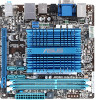
1.2 1.2.1 Motherboard overview Motherboard layout ASUS AT3IONT-I Series motherboards include AT3IONT-I and AT3IONT-I /O 5 CPU_FAN Intel® HDMI VGA Place this user guide are for AT3IONT-I DELUXE only. The edge with external ports goes to the chassis. DO NOT overtighten the screws! Doing so...SATA4) Front panel audio connector (10-1 pin AAFP) USB connector (10-1 pin USB78, USB910) Page 1-14 1-8 1-1 1-11 1-13 1-12 ASUS AT3IONT-I DELUXE Lithium Cell CMOS Power DDR3 DIMM_A1 (64bit, 240-pin module) BT_USB34 LAN1_USB12 RCA_OUT AUDIO RTL 8112L AAFP ALC 887 USB910 USB78 NVIDIA® ...
1.2 1.2.1 Motherboard overview Motherboard layout ASUS AT3IONT-I Series motherboards include AT3IONT-I and AT3IONT-I /O 5 CPU_FAN Intel® HDMI VGA Place this user guide are for AT3IONT-I DELUXE only. The edge with external ports goes to the chassis. DO NOT overtighten the screws! Doing so...SATA4) Front panel audio connector (10-1 pin AAFP) USB connector (10-1 pin USB78, USB910) Page 1-14 1-8 1-1 1-11 1-13 1-12 ASUS AT3IONT-I DELUXE Lithium Cell CMOS Power DDR3 DIMM_A1 (64bit, 240-pin module) BT_USB34 LAN1_USB12 RCA_OUT AUDIO RTL 8112L AAFP ALC 887 USB910 USB78 NVIDIA® ...
AT3IONT-I Series user's manual
Page 12
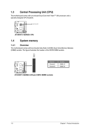
AT3IONT-I SERIES CPU 1.4 System memory 1.4.1 Overview The motherboard comes with an onboard Dual-Core Intel® Atom™ 330 processor and a specially designed CPU heatsink. Intel® Atom330 AT3IONT-I DELUXE 1.3 Central Processing Unit (CPU) The motherboard comes with two Double Data Rate 3 (DDR3) Dual Inline Memory Modules (DIMM) sockets. The figure illustrates the location of the DDR3 DIMM sockets: AT3IONT-I DELUXE DIMM_B1 DIMM_A1 Channel Channel A Channel B Sockets DIMM_A1 DIMM_B1 AT3IONT-I SERIES 240-pin DDR3 DIMM sockets 1-3 Chapter 1: Product introduction
AT3IONT-I SERIES CPU 1.4 System memory 1.4.1 Overview The motherboard comes with an onboard Dual-Core Intel® Atom™ 330 processor and a specially designed CPU heatsink. Intel® Atom330 AT3IONT-I DELUXE 1.3 Central Processing Unit (CPU) The motherboard comes with two Double Data Rate 3 (DDR3) Dual Inline Memory Modules (DIMM) sockets. The figure illustrates the location of the DDR3 DIMM sockets: AT3IONT-I DELUXE DIMM_B1 DIMM_A1 Channel Channel A Channel B Sockets DIMM_A1 DIMM_B1 AT3IONT-I SERIES 240-pin DDR3 DIMM sockets 1-3 Chapter 1: Product introduction
AT3IONT-I Series user's manual
Page 13
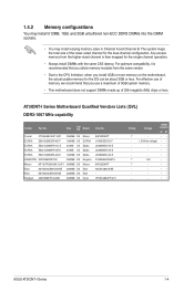
... support A* B* - •• 1.35V(low voltage) • • - •• - •• - •• 1.5V •• - •• - •• - •• - •• ASUS AT3IONT-I Series Motherboard Qualified Vendors Lists (QVL) DDR3-1067 MHz capability Vendor Part No. Any excess memory from the same vendor. • Due to the CPU...
... support A* B* - •• 1.35V(low voltage) • • - •• - •• - •• 1.5V •• - •• - •• - •• - •• ASUS AT3IONT-I Series Motherboard Qualified Vendors Lists (QVL) DDR3-1067 MHz capability Vendor Part No. Any excess memory from the same vendor. • Due to the CPU...

AT3IONT-I Series user's manual
Page 14
Timing AD30908C8D-151C E0906 - DIMM support A* B •• (continued on the next page) 1-5 Chapter 1: Product introduction AD30908C8D-151C E0903 - - 8-8-8-24 AM5D5808DEWSBG - - 9-9-9-24 - - - 9-9-9-24 - 9-9-9-24 - - - - - 9-9-9-24 9FF22D9KPT 9 - 6-6-6-20 9KF27D9KPT 9 - 6-6-6-20 - 6-6-6-20 J1108EDSE-DJ-F - - F3-10600CL9D-2GBNQ 1024MB DS G.SKILL F3-10666CL8D-4GBECO(XMP) 4096MB(Kit of 3) SS - Size SS/ DS Brand A-Data A-Data A-Data Apacer CORSAIR CORSAIR CORSAIR CORSAIR CORSAIR CORSAIR CORSAIR Crucial Crucial Crucial ...
Timing AD30908C8D-151C E0906 - DIMM support A* B •• (continued on the next page) 1-5 Chapter 1: Product introduction AD30908C8D-151C E0903 - - 8-8-8-24 AM5D5808DEWSBG - - 9-9-9-24 - - - 9-9-9-24 - 9-9-9-24 - - - - - 9-9-9-24 9FF22D9KPT 9 - 6-6-6-20 9KF27D9KPT 9 - 6-6-6-20 - 6-6-6-20 J1108EDSE-DJ-F - - F3-10600CL9D-2GBNQ 1024MB DS G.SKILL F3-10666CL8D-4GBECO(XMP) 4096MB(Kit of 3) SS - Size SS/ DS Brand A-Data A-Data A-Data Apacer CORSAIR CORSAIR CORSAIR CORSAIR CORSAIR CORSAIR CORSAIR Crucial Crucial Crucial ...
AT3IONT-I Series user's manual
Page 15
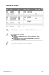
Timing 7-7-7-20 7-7-7-20 7-7-7-20 - Visit the ASUS website at 1066MHz on AT3IONT-I Series 1-6 DDR3-1333 MHz capability Vendor Part No. J1108BASE-DJ-E J1108BASE-DJ-E 8FD22D9JNM 8DD22D9JNM SEC 904 HCH9 K4B1G0846D PM64M8D38U-15 - Voltage - SS: Single-sided /... 2048MB 1024MB 2048MB 2048MB 2048MB 2048MB Kingtiger PATRIOT PATRIOT PATRIOT KTG2G1333PG3 PSD31G13332H PSD31G13332 PSD32G13332H 2048MB 1024MB 1024MB 2048MB SS/ DS Brand Chip No. ASUS AT3IONT-I Series motherboards. SS ELPIDA DS ELPIDA SS DS SS Micron DS Micron DS DS Elixir DS Samsung DS DS DS Patriot DS -
Timing 7-7-7-20 7-7-7-20 7-7-7-20 - Visit the ASUS website at 1066MHz on AT3IONT-I Series 1-6 DDR3-1333 MHz capability Vendor Part No. J1108BASE-DJ-E J1108BASE-DJ-E 8FD22D9JNM 8DD22D9JNM SEC 904 HCH9 K4B1G0846D PM64M8D38U-15 - Voltage - SS: Single-sided /... 2048MB 1024MB 2048MB 2048MB 2048MB 2048MB Kingtiger PATRIOT PATRIOT PATRIOT KTG2G1333PG3 PSD31G13332H PSD31G13332 PSD32G13332H 2048MB 1024MB 1024MB 2048MB SS/ DS Brand Chip No. ASUS AT3IONT-I Series motherboards. SS ELPIDA DS ELPIDA SS DS SS Micron DS Micron DS DS Elixir DS Samsung DS DS DS Patriot DS -

AT3IONT-I Series user's manual
Page 16
Unplug the power cord before adding or removing expansion cards. Remove the bracket opposite the slot that it supports. Assign an IRQ to the chassis with it by adjusting the software settings. 1. Align the card connector with the PCI Express specifications. 1-7 Chapter 1: Product introduction Before installing the expansion card, read the documentation that complies with the slot and press firmly until the card is already installed in a chassis). 3. Remove the system unit cover (if your motherboard is completely seated on the system and change the necessary BIOS ...
Unplug the power cord before adding or removing expansion cards. Remove the bracket opposite the slot that it supports. Assign an IRQ to the chassis with it by adjusting the software settings. 1. Align the card connector with the PCI Express specifications. 1-7 Chapter 1: Product introduction Before installing the expansion card, read the documentation that complies with the slot and press firmly until the card is already installed in a chassis). 3. Remove the system unit cover (if your motherboard is completely seated on the system and change the necessary BIOS ...
AT3IONT-I Series user's manual
Page 17
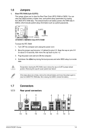
... 23 CLRTC Normal (Default) Clear RTC AT3IONT-I Series 1-8 Move the jumper cap from pins 1-2 (default) to re-enter data. The onboard button cell battery powers the RAM data in CMOS. Except when ...) This jumper allows you to pins 1-2. 3. After clearing the CMOS, reinstall the battery. 1.7 Connectors 1.7.1 Rear panel connectors 1 2 3 4 5 6 78 16 15 14 13 12 11 10 9 ASUS AT3IONT-I SERIES Clear RTC RAM To erase the RTC RAM: 1. Keep the cap on CLRTC jumper default position. You can clear the CMOS memory of date...
... 23 CLRTC Normal (Default) Clear RTC AT3IONT-I Series 1-8 Move the jumper cap from pins 1-2 (default) to re-enter data. The onboard button cell battery powers the RAM data in CMOS. Except when ...) This jumper allows you to pins 1-2. 3. After clearing the CMOS, reinstall the battery. 1.7 Connectors 1.7.1 Rear panel connectors 1 2 3 4 5 6 78 16 15 14 13 12 11 10 9 ASUS AT3IONT-I SERIES Clear RTC RAM To erase the RTC RAM: 1. Keep the cap on CLRTC jumper default position. You can clear the CMOS memory of date...

AT3IONT-I Series user's manual
Page 18
... 32KB data RAM and 256KB program RAM; 5V single supply voltage. • Under Windows® XP, if the Bluetooth Driver item is for AT3IONT-I DELUXE only). LAN (RJ-45) port. This port allows Gigabit connection to the WLAN antenna. 2. Line In port (light blue). This ...8. Line Out port (lime). Video Graphics Adapter (VGA) port. Switch on the Support DVD's Drivers screen, follow the steps below for AT3IONT-I DELUXE only). Open the Support DVD and click ASUS InstAll. 5. This port connects a receiver or a TV via an RCA cable. 7. RCA Out port (right-channel) (for a PS...
... 32KB data RAM and 256KB program RAM; 5V single supply voltage. • Under Windows® XP, if the Bluetooth Driver item is for AT3IONT-I DELUXE only). LAN (RJ-45) port. This port allows Gigabit connection to the WLAN antenna. 2. Line In port (light blue). This ...8. Line Out port (lime). Video Graphics Adapter (VGA) port. Switch on the Support DVD's Drivers screen, follow the steps below for AT3IONT-I DELUXE only). Open the Support DVD and click ASUS InstAll. 5. This port connects a receiver or a TV via an RCA cable. 7. RCA Out port (right-channel) (for a PS...
AT3IONT-I Series user's manual
Page 19
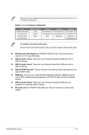
... This port connects to an external audio output device via an RCA cable. 11. These two 4-pin Universal Serial Bus (USB) ports are for AT3IONT-I DELUXE only). ASUS AT3IONT-I DELUXE only). USB 2.0 ports 3 and 4. Refer to the audio configuration table below for the function of HD DVD, Blu-Ray, and other protected content...
... This port connects to an external audio output device via an RCA cable. 11. These two 4-pin Universal Serial Bus (USB) ports are for AT3IONT-I DELUXE only). ASUS AT3IONT-I DELUXE only). USB 2.0 ports 3 and 4. Refer to the audio configuration table below for the function of HD DVD, Blu-Ray, and other protected content...

AT3IONT-I Series user's manual
Page 20
... MB/s). SATA1 SATA3 GND RSATA_RXN1 RSATA_RXP1 GND RSATA_TXN1 RSATA_TXP1 GND GND RSATA_TXP3 RSATA_TXN3 GND RSATA_RXP3 RSATA_RXN3 GND AT3IONT-I DELUXE SATA2 GND RSATA_RXN2 RSATA_RXP2 GND RSATA_TXN2 RSATA_TXP2 GND SATA4 GND RSATA_TXP4 RSATA_TXN4 GND RSATA_RXP4 RSATA_RXN4 GND AT3IONT-I SERIES SATA connectors • Install the Windows® XP Service Pack 2 or later versions before using...
... MB/s). SATA1 SATA3 GND RSATA_RXN1 RSATA_RXP1 GND RSATA_TXN1 RSATA_TXP1 GND GND RSATA_TXP3 RSATA_TXN3 GND RSATA_RXP3 RSATA_RXN3 GND AT3IONT-I DELUXE SATA2 GND RSATA_RXN2 RSATA_RXP2 GND RSATA_TXN2 RSATA_TXP2 GND SATA4 GND RSATA_TXP4 RSATA_TXN4 GND RSATA_RXP4 RSATA_RXN4 GND AT3IONT-I SERIES SATA connectors • Install the Windows® XP Service Pack 2 or later versions before using...
