
User Manual
Page 1
AT3GC-I Motherboard
AT3GC-I Motherboard

User Manual
Page 3
Contents Notices...v Safety information vi About this guide vi AT3GC-I specifications summary viii Chapter 1: Product introduction 1.1 Before you proceed 1-1 1.2 Motherboard overview 1-2 1.2.1 Motherboard layout 1-2 1.2.2 Layout contents 1-2 1.3 Central Processing Unit (CPU 1-3 1.4 System memory 1-3 1.4.1 Overview 1-3 1.4.2 Memory ...14 Chapter 2: BIOS information 2.1 Managing and updating your BIOS 2-1 2.1.1 ASUS Update utility 2-1 2.1.2 ASUS EZ Flash 2 utility 2-2 2.1.3 ASUS CrashFree BIOS 3 utility 2-3 2.2 BIOS setup program 2-4 2.3 Main menu 2-4 2.3.1 System Time 2-4 iii
Contents Notices...v Safety information vi About this guide vi AT3GC-I specifications summary viii Chapter 1: Product introduction 1.1 Before you proceed 1-1 1.2 Motherboard overview 1-2 1.2.1 Motherboard layout 1-2 1.2.2 Layout contents 1-2 1.3 Central Processing Unit (CPU 1-3 1.4 System memory 1-3 1.4.1 Overview 1-3 1.4.2 Memory ...14 Chapter 2: BIOS information 2.1 Managing and updating your BIOS 2-1 2.1.1 ASUS Update utility 2-1 2.1.2 ASUS EZ Flash 2 utility 2-2 2.1.3 ASUS CrashFree BIOS 3 utility 2-3 2.2 BIOS setup program 2-4 2.3 Main menu 2-4 2.3.1 System Time 2-4 iii

User Manual
Page 5
... undesired operation. If this unit not expressly approved by one or more of Chemicals) regulatory framework, we published the chemical substances in our products at ASUS REACH website at http://green.asus.com/english/REACH.htm DO NOT throw the motherboard in a residential installation.
... undesired operation. If this unit not expressly approved by one or more of Chemicals) regulatory framework, we published the chemical substances in our products at ASUS REACH website at http://green.asus.com/english/REACH.htm DO NOT throw the motherboard in a residential installation.
User Manual
Page 6
...; If the power supply is broken, do not try to fix it by yourself. If you are not sure about the voltage of the motherboard and the new technology it , carefully read all the manuals that came with the product, contact a qualified service technician or your dealer immediately....change system settings through the BIOS setup menus. How this guide This user guide contains the information you need when installing and configuring the motherboard. If possible, disconnect all power cables from the existing system before using an adapter or extension cord. These devices could interrupt the ...
...; If the power supply is broken, do not try to fix it by yourself. If you are not sure about the voltage of the motherboard and the new technology it , carefully read all the manuals that came with the product, contact a qualified service technician or your dealer immediately....change system settings through the BIOS setup menus. How this guide This user guide contains the information you need when installing and configuring the motherboard. If possible, disconnect all power cables from the existing system before using an adapter or extension cord. These devices could interrupt the ...
User Manual
Page 10
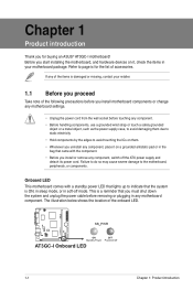
...any component, switch off mode. Failure to do so may cause severe damage to page ix for buying an ASUS® AT3GC-I Onboard LED 1-1 Chapter 1: Product introduction AT3GC-I AT3GC-I motherboard! If any of the items is a reminder that came with a standby power LED that lights up to avoid...This is damaged or missing, contact your retailer. 1.1 Before you proceed Take note of the following precautions before you install motherboard components or change any motherboard settings. • Unplug the power cord from the wall socket before removing or plugging in any component, place it ,...
...any component, switch off mode. Failure to do so may cause severe damage to page ix for buying an ASUS® AT3GC-I Onboard LED 1-1 Chapter 1: Product introduction AT3GC-I AT3GC-I motherboard! If any of the items is a reminder that came with a standby power LED that lights up to avoid...This is damaged or missing, contact your retailer. 1.1 Before you proceed Take note of the following precautions before you install motherboard components or change any motherboard settings. • Unplug the power cord from the wall socket before removing or plugging in any component, place it ,...

User Manual
Page 11
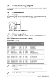
... KBPWR) 2. Front panel audio connector (10-1 pin AAFP) 1-13 1-9 16. Optical drive audio in connector (4-pin CD) 1-8 ASUS AT3GC-I DDR2 DIMM1 (64bit, 240-pin module) CLRTC EATXPWR LPT VGA USBPW1-4 Intel® 945GC Lithium Cell CMOS Power USB34 RTL 8112 LAN1_USB12...(4- IDE connector (40-1 pin PRI_IDE) Page Connectors/Jumpers/Slots/LED Page 1-6 9. 1.2 1.2.1 Motherboard overview Motherboard layout Ensure that you install the motherboard into the holes indicated by circles to secure the motherboard to the rear part of the chassis. 12 3 4 5 17.1cm(6.75in) 67 KBMS ...
... KBPWR) 2. Front panel audio connector (10-1 pin AAFP) 1-13 1-9 16. Optical drive audio in connector (4-pin CD) 1-8 ASUS AT3GC-I DDR2 DIMM1 (64bit, 240-pin module) CLRTC EATXPWR LPT VGA USBPW1-4 Intel® 945GC Lithium Cell CMOS Power USB34 RTL 8112 LAN1_USB12...(4- IDE connector (40-1 pin PRI_IDE) Page Connectors/Jumpers/Slots/LED Page 1-6 9. 1.2 1.2.1 Motherboard overview Motherboard layout Ensure that you install the motherboard into the holes indicated by circles to secure the motherboard to the rear part of the chassis. 12 3 4 5 17.1cm(6.75in) 67 KBMS ...
User Manual
Page 12
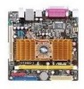
...-channel memory configuration. Visit the ASUS website at www.asus.com for the latest QVL. 1-3 Chapter 1: Product introduction 1.3 Central Processing Unit (CPU) The motherboard comes with an onboard Intel®...; Atom 330 processor and a specially designed CPU heatsink. 1.4 System memory 1.4.1 Overview The motherboard comes with one module inserted into the DIMM socket. The figure illustrates the location of the DDR2 DIMM socket: AT3GC...
...-channel memory configuration. Visit the ASUS website at www.asus.com for the latest QVL. 1-3 Chapter 1: Product introduction 1.3 Central Processing Unit (CPU) The motherboard comes with an onboard Intel®...; Atom 330 processor and a specially designed CPU heatsink. 1.4 System memory 1.4.1 Overview The motherboard comes with one module inserted into the DIMM socket. The figure illustrates the location of the DDR2 DIMM socket: AT3GC...

User Manual
Page 13
...card. Assign an IRQ to the chassis with the slot and press firmly until the card is already installed in a chassis). 3. ASUS AT3GC-I 1-4 Unplug the power cord before adding or removing expansion cards. Remove the bracket opposite the slot that comply with it by adjusting... install expansion cards. 1.5 Expansion slots In the future, you physical injury and damage motherboard components. 1.5.1 Installing an expansion card To install an expansion card: 1. Remove the chassis cover (if your motherboard is completely seated on BIOS setup. 2. Replace the chassis cover. 1.5.2 Configuring an...
...card. Assign an IRQ to the chassis with the slot and press firmly until the card is already installed in a chassis). 3. ASUS AT3GC-I 1-4 Unplug the power cord before adding or removing expansion cards. Remove the bracket opposite the slot that comply with it by adjusting... install expansion cards. 1.5 Expansion slots In the future, you physical injury and damage motherboard components. 1.5.1 Installing an expansion card To install an expansion card: 1. Remove the chassis cover (if your motherboard is completely seated on BIOS setup. 2. Replace the chassis cover. 1.5.2 Configuring an...

User Manual
Page 18
3. AT3GC-I PIN1 NOTE:Orient the red markings on the IDE ribbon cable to configure your devices. IDE connector (40-1 pin PRI_IDE) The onboard IDE connector is ... Slave Master Slave Cable connector Black Black Gray Black or gray Pin 20 on the IDE connector is removed to the motherboard's IDE connector, then select one of device(s) - PRI_IDE AT3GC-I IDE connector 1-9 Chapter 1: Product introduction This prevents incorrect insertion when you connect the IDE cable. • If any device jumper is...
3. AT3GC-I PIN1 NOTE:Orient the red markings on the IDE ribbon cable to configure your devices. IDE connector (40-1 pin PRI_IDE) The onboard IDE connector is ... Slave Master Slave Cable connector Black Black Gray Black or gray Pin 20 on the IDE connector is removed to the motherboard's IDE connector, then select one of device(s) - PRI_IDE AT3GC-I IDE connector 1-9 Chapter 1: Product introduction This prevents incorrect insertion when you connect the IDE cable. • If any device jumper is...

User Manual
Page 19
...the back of the system chassis. DO NOT place jumper cap on the motherboard, ensuring that supports up to the USB connectors. USB_P5- CHA_FAN GND +12V Rotation AT3GC-I fan connectors AT3GC-I ASUS AT3GC-I USB2.0 connectors Never connect a 1394 cable to 480Mbps connection speed. ...Insufficient air flow inside the system may damage the motherboard components. Connect the USB module cable to any of...
...the back of the system chassis. DO NOT place jumper cap on the motherboard, ensuring that supports up to the USB connectors. USB_P5- CHA_FAN GND +12V Rotation AT3GC-I fan connectors AT3GC-I ASUS AT3GC-I USB2.0 connectors Never connect a 1394 cable to 480Mbps connection speed. ...Insufficient air flow inside the system may damage the motherboard components. Connect the USB module cable to any of...

User Manual
Page 23
... Support DVD to locate the file ASSETUP.EXE from the BIN folder. Click an icon to display Support DVD/ motherboard information Click an item to get all motherboard features. Visit the ASUS website at any time without notice. Always install the latest OS version and corresponding updates to maximize the features of... Pack 1 or later versions before installing the drivers for updates. Double-click ASSETUP.EXE to your computer. 1.8 Software support 1.8.1 Installing an operating system This motherboard supports Windows® XP/Vista Operating Systems (OS). ASUS AT3GC-I 1-14
... Support DVD to locate the file ASSETUP.EXE from the BIN folder. Click an icon to display Support DVD/ motherboard information Click an item to get all motherboard features. Visit the ASUS website at any time without notice. Always install the latest OS version and corresponding updates to maximize the features of... Pack 1 or later versions before installing the drivers for updates. Double-click ASSETUP.EXE to your computer. 1.8 Software support 1.8.1 Installing an operating system This motherboard supports Windows® XP/Vista Operating Systems (OS). ASUS AT3GC-I 1-14

User Manual
Page 24
... the following methods: Updating from the Internet, then click Next. Quit all its features. 2-1 ASUS AT3GC-I The ASUS Update utility is a utility that comes with the motherboard package. Select Update BIOS from the Internet a. Follow the onscreen instructions to launch the ASUS Update utility. 2. From the dropdown list, select either through the Internet. Select the...
... the following methods: Updating from the Internet, then click Next. Quit all its features. 2-1 ASUS AT3GC-I The ASUS Update utility is a utility that comes with the motherboard package. Select Update BIOS from the Internet a. Follow the onscreen instructions to launch the ASUS Update utility. 2. From the dropdown list, select either through the Internet. Select the...
User Manual
Page 26
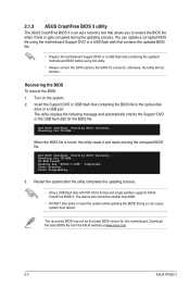
... at www.asus.com. 2-3 ASUS AT3GC-I .ROM". The utility displays the following message and automatically checks the Support DVD or the USB flash disk for this utility. • Always connect the SATA cable to the SATA1/2 connector; Bad BIOS checksum. Reading file "AT3GC-I Doing so can update a corrupted BIOS file using the motherboard Support DVD...
... at www.asus.com. 2-3 ASUS AT3GC-I .ROM". The utility displays the following message and automatically checks the Support DVD or the USB flash disk for this utility. • Always connect the SATA cable to the SATA1/2 connector; Bad BIOS checksum. Reading file "AT3GC-I Doing so can update a corrupted BIOS file using the motherboard Support DVD...

User Manual
Page 27
...on the system chassis. • Press the power button to turn the system off then back on your screen. • Visit the ASUS website at www.asus.com to download the latest BIOS file for reference only. Chapter 2: BIOS information 2-4 If the system becomes unstable after POST, reboot the... menu When you enter the BIOS Setup program, the Main menu screen appears, giving you are for this section are installing a motherboard, reconfiguring your system using the OS standard shut-down the system properly from a running operating system can cause damage to ensure optimum ...
...on the system chassis. • Press the power button to turn the system off then back on your screen. • Visit the ASUS website at www.asus.com to download the latest BIOS file for reference only. Chapter 2: BIOS information 2-4 If the system becomes unstable after POST, reboot the... menu When you enter the BIOS Setup program, the Main menu screen appears, giving you are for this section are installing a motherboard, reconfiguring your system using the OS standard shut-down the system properly from a running operating system can cause damage to ensure optimum ...

User Manual
Page 35
... on the system. This feature requires an ATX power supply that provides at least 1A on the system. Select an item then press to the motherboard, the field shows N/A. Select Ignored if you do not wish to display the detected voltage output. 2.6 Boot menu The Boot menu items allow you to...
... on the system. This feature requires an ATX power supply that provides at least 1A on the system. Select an item then press to the motherboard, the field shows N/A. Select Ignored if you do not wish to display the detected voltage output. 2.6 Boot menu The Boot menu items allow you to...


