
Hardware Reference Guide
Page 4
... Front Connections 19 Hot-Swap Tray Connector Board 20 Hot-Swap Tray Rear Connections 20 Motherboard Securing 21 Spacer Mounts 21 SCSI Backplane 22 SCSI Board Placement 22 SCSI ID Setting 23 SCSI ID Dip Switches 23 4 AP7500 Hardware Reference Guide Introduction 7 This Reference Guide 7 Sections 7 Symbols 7 This Server 8 Component Checklist 8 Features...
... Front Connections 19 Hot-Swap Tray Connector Board 20 Hot-Swap Tray Rear Connections 20 Motherboard Securing 21 Spacer Mounts 21 SCSI Backplane 22 SCSI Board Placement 22 SCSI ID Setting 23 SCSI ID Dip Switches 23 4 AP7500 Hardware Reference Guide Introduction 7 This Reference Guide 7 Sections 7 Symbols 7 This Server 8 Component Checklist 8 Features...
Hardware Reference Guide
Page 8
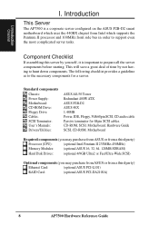
... is a corporate server configured on the ASUS P2B-D2 smart motherboard which uses the 440BX chipset from a third party) Ethernet Card: (optional ASUS PCI-L101) RAID Card: (optional ASUS PCI-DA2100A) 8 AP7500 Hardware Reference Guide CD-ROM, SCSI, Motherboard, Hardware Guide SCSI, CD-ROM, Motherboard Required components (you may purchase from ASUS or from a third party) Processor (CPU...
... is a corporate server configured on the ASUS P2B-D2 smart motherboard which uses the 440BX chipset from a third party) Ethernet Card: (optional ASUS PCI-L101) RAID Card: (optional ASUS PCI-DA2100A) 8 AP7500 Hardware Reference Guide CD-ROM, SCSI, Motherboard, Hardware Guide SCSI, CD-ROM, Motherboard Required components (you may purchase from ASUS or from a third party) Processor (CPU...
Hardware Reference Guide
Page 9
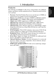
For additional features and details, read the motherboard User's Manual included with remote SCSI ID dip switches and power to support up to 8 wide-SCSI hard disk drives. • Redundant Power: Dual 400W ... and processor voltages, fan speed, temperature, chassis intrusion, and provides automatic system restart. • SNMP Agent and Intel LDSM: Provides server monitoring, management, and control. AP7500 Hardware Reference Guide 9 Introduction Features The following are highlights to this server package. • Processor: Dual Intel Pentium II processors provide up to 450MHz on...
For additional features and details, read the motherboard User's Manual included with remote SCSI ID dip switches and power to support up to 8 wide-SCSI hard disk drives. • Redundant Power: Dual 400W ... and processor voltages, fan speed, temperature, chassis intrusion, and provides automatic system restart. • SNMP Agent and Intel LDSM: Provides server monitoring, management, and control. AP7500 Hardware Reference Guide 9 Introduction Features The following are highlights to this server package. • Processor: Dual Intel Pentium II processors provide up to 450MHz on...

Hardware Reference Guide
Page 10
...or pins. • If you are ready to avoid electrical shock. I . These devices are sensitive to prevent permanent damage. 10 AP7500 Hardware Reference Guide Before picking it to a metal frame of the system unit at the same time. • Handle the devices carefully... in antistatic bags to or from the existing system before the signal cables are unplugged. Static-Sensitive Devices CAUTION: Motherboards, adapters, and disk drives are wrapped in order to static electricity discharge. Introduction Safety and Warning Observe the following precautions: •...
...or pins. • If you are ready to avoid electrical shock. I . These devices are sensitive to prevent permanent damage. 10 AP7500 Hardware Reference Guide Before picking it to a metal frame of the system unit at the same time. • Handle the devices carefully... in antistatic bags to or from the existing system before the signal cables are unplugged. Static-Sensitive Devices CAUTION: Motherboards, adapters, and disk drives are wrapped in order to static electricity discharge. Introduction Safety and Warning Observe the following precautions: •...

Hardware Reference Guide
Page 11
...power in the power supply in this hardware reference guide along with your server, do not bypass the grounding plug. Unpack your motherboard manual in the server if one is designed for 120V-140V areas. Connect server to network (an optional network card is ... used. Install final server components such as a UPS or power strip (preferably with a lockable panel to make these installations. 4. AP7500 Hardware Reference Guide 11 Use this server. • Phillips (cross) screwdriver • Standard (flat) screwdriver • Antistatic wrist strap Preparation 1.
...power in the power supply in this hardware reference guide along with your server, do not bypass the grounding plug. Unpack your motherboard manual in the server if one is designed for 120V-140V areas. Connect server to network (an optional network card is ... used. Install final server components such as a UPS or power strip (preferably with a lockable panel to make these installations. 4. AP7500 Hardware Reference Guide 11 Use this server. • Phillips (cross) screwdriver • Standard (flat) screwdriver • Antistatic wrist strap Preparation 1.

Hardware Reference Guide
Page 13
... alerting and logging with the built-in keylock. II. If either one or both of the side panels are opened, the motherboard's onboard hardware monitor can be connected to the motherboard's "chassis" connector to show the back exterior components of the chassis side panels' open/close status. System Components Server Back Side...
... alerting and logging with the built-in keylock. II. If either one or both of the side panels are opened, the motherboard's onboard hardware monitor can be connected to the motherboard's "chassis" connector to show the back exterior components of the chassis side panels' open/close status. System Components Server Back Side...
Hardware Reference Guide
Page 21
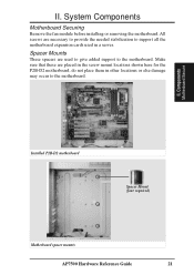
...the screw mount locations shown here for the P2B-D2 motherboard, do not place them in a server. All screws are used in other locations or else damage may occur to the motherboard. Spacer Mounts These spacers are necessary to provide the ...needed stabilization to support all the motherboard expansion cards used to give added support to the motherboard. Components Motherboard Secure Installed P2B-D2 motherboard Spacer Mount (four required) Motherboard spacer mounts AP7500 Hardware Reference Guide...
...the screw mount locations shown here for the P2B-D2 motherboard, do not place them in a server. All screws are used in other locations or else damage may occur to the motherboard. Spacer Mounts These spacers are necessary to provide the ...needed stabilization to support all the motherboard expansion cards used to give added support to the motherboard. Components Motherboard Secure Installed P2B-D2 motherboard Spacer Mount (four required) Motherboard spacer mounts AP7500 Hardware Reference Guide...
Hardware Reference Guide
Page 24
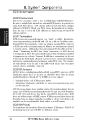
... highest priority, and SCSI ID 0 has the lowest priority. 24 AP7500 Hardware Reference Guide System Components SCSI Information SCSI Connections Your server can prevent SCSI address conflicts. If there are more devices try to the motherboard with its ID number. SCSI IDs on the bus. • ... installed single-ended SCSI devices. You must have a SCSI identification number that you can support up to 15 SCSI devices to this motherboard with cables to the manual for each SCSI device on one internal or external device, additional devices are connected with onboard SCSI, must...
... highest priority, and SCSI ID 0 has the lowest priority. 24 AP7500 Hardware Reference Guide System Components SCSI Information SCSI Connections Your server can prevent SCSI address conflicts. If there are more devices try to the motherboard with its ID number. SCSI IDs on the bus. • ... installed single-ended SCSI devices. You must have a SCSI identification number that you can support up to 15 SCSI devices to this motherboard with cables to the manual for each SCSI device on one internal or external device, additional devices are connected with onboard SCSI, must...

Hardware Reference Guide
Page 25
...pin WideSCSI Cables (for connecting devices in the server. RAID connections require the ASUS PCI-DA2100A RAID card. Plastic keepers protect the cables from devices Cable Connections The cables connect to the motherboard as shown. The P2B-DS includes onboard SCSI with the fans and other ... 68-pin and 50-pin SCSI connectors. Components Device Cables II. Floppy Cable ASUS RAID Card: SCSI Cable Ch. 0 SCSI Cable Ch. 1 SCSI Cable (underneath) IDE Cable Motherboard with cables connected AP7500 Hardware Reference Guide 25 II. The following picture points out the name of each...
...pin WideSCSI Cables (for connecting devices in the server. RAID connections require the ASUS PCI-DA2100A RAID card. Plastic keepers protect the cables from devices Cable Connections The cables connect to the motherboard as shown. The P2B-DS includes onboard SCSI with the fans and other ... 68-pin and 50-pin SCSI connectors. Components Device Cables II. Floppy Cable ASUS RAID Card: SCSI Cable Ch. 0 SCSI Cable Ch. 1 SCSI Cable (underneath) IDE Cable Motherboard with cables connected AP7500 Hardware Reference Guide 25 II. The following picture points out the name of each...

Hardware Reference Guide
Page 27
... cables should face each other. System Components IDE Cabling Proper IDE device operation requires that travels through the signal cable. Remove unused cables from the motherboard's IDE connector to the end of IDE hard disk drives. CD audio output CD-ROM drive connections NOTE: A CD-ROM audio cable is used, connect...-ROM disk drive mounts only in one IDE device is also provided in case you install an audio card. The red stripe of power cable AP7500 Hardware Reference Guide 27 II. Components IDE Cable / CD-ROM II.
... cables should face each other. System Components IDE Cabling Proper IDE device operation requires that travels through the signal cable. Remove unused cables from the motherboard's IDE connector to the end of IDE hard disk drives. CD audio output CD-ROM drive connections NOTE: A CD-ROM audio cable is used, connect...-ROM disk drive mounts only in one IDE device is also provided in case you install an audio card. The red stripe of power cable AP7500 Hardware Reference Guide 27 II. Components IDE Cable / CD-ROM II.

Hardware Reference Guide
Page 29
One AGP slot is also available for a hardware 3D accelerator with the expansion slot on the motherboard and gently lower and push the card into the free slot. 7. Ensure the jumpers (if any standard PC computer. AP7500 Hardware Reference Guide 29 System Components Expansion Cards Expansion cards can be easily installed just like...
One AGP slot is also available for a hardware 3D accelerator with the expansion slot on the motherboard and gently lower and push the card into the free slot. 7. Ensure the jumpers (if any standard PC computer. AP7500 Hardware Reference Guide 29 System Components Expansion Cards Expansion cards can be easily installed just like...
Hardware Reference Guide
Page 31
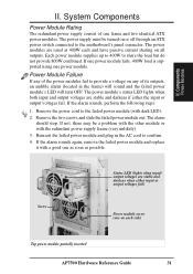
II. The power modules are rated at 400W each side) Top power module partially inserted AP7500 Hardware Reference Guide 31 Each power module supplies up to 400W to the failed power module (with dark LED). 2. If the alarm sounds, perform the .... Power Module Failure If any of one on each and have passive current sharing on or off through an ATX power switch connected to the motherboard's panel connector. The power module's status LED lights when both input and output voltages are stable and darkens when either the input or output voltages...
II. The power modules are rated at 400W each side) Top power module partially inserted AP7500 Hardware Reference Guide 31 Each power module supplies up to 400W to the failed power module (with dark LED). 2. If the alarm sounds, perform the .... Power Module Failure If any of one on each and have passive current sharing on or off through an ATX power switch connected to the motherboard's panel connector. The power module's status LED lights when both input and output voltages are stable and darkens when either the input or output voltages...
Hardware Reference Guide
Page 32
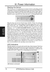
... to use RAID on your server if they are located on front panel 32 AP7500 Hardware Reference Guide LED Indicators The LED indicators are not included in the operating ...boot disk in order to boot from a floppy diskette to install a RAID card, such as the ASUS PCI-DA2100A and then run the RAID setup program from IDE or SCSI devices connected to install drivers... diskette and select "Save & Exit Setup" from the power supply. III. The Power LED lights when the motherboard receives power from the BIOS main menu. Fan #1-5 lights if the corresponding fan stops turning. If the Power ...
... to use RAID on your server if they are located on front panel 32 AP7500 Hardware Reference Guide LED Indicators The LED indicators are not included in the operating ...boot disk in order to boot from a floppy diskette to install a RAID card, such as the ASUS PCI-DA2100A and then run the RAID setup program from IDE or SCSI devices connected to install drivers... diskette and select "Save & Exit Setup" from the power supply. III. The Power LED lights when the motherboard receives power from the BIOS main menu. Fan #1-5 lights if the corresponding fan stops turning. If the Power ...

Hardware Reference Guide
Page 33
... any one time. CAUTION: Exceeding the SCSI cable limits may cause unreliable data transfers even if all the devices are for devices on the motherboard. The following "Max Devices" are mounted properly. Mixing SCSI devices is reserved for the above . III. NOTE: If connecting Fast/Ultra... unstable over long lengths, therefore stability will depend on the Ultra2 connector, the entire SCSI bus will be connected to the 50-pin Narrow connector. AP7500 Hardware Reference Guide 33 Cable Limits 1) 12m (29.4ft) 2) 3m - 1.5m 3) 3m (9.8ft) 4) 3m - 1.5m 5) 3m (9.8ft) Max Data ...
... any one time. CAUTION: Exceeding the SCSI cable limits may cause unreliable data transfers even if all the devices are for devices on the motherboard. The following "Max Devices" are mounted properly. Mixing SCSI devices is reserved for the above . III. NOTE: If connecting Fast/Ultra... unstable over long lengths, therefore stability will depend on the Ultra2 connector, the entire SCSI bus will be connected to the 50-pin Narrow connector. AP7500 Hardware Reference Guide 33 Cable Limits 1) 12m (29.4ft) 2) 3m - 1.5m 3) 3m (9.8ft) 4) 3m - 1.5m 5) 3m (9.8ft) Max Data ...

Hardware Reference Guide
Page 35
Appendix Power Requirement AP7500 Hardware Reference Guide 35 III. Appendix Power Supply Requirement Calculation Table Item Volts Amp x Qty. = TotalAmp Watts (5V) Watts (12V) Total Motherboard Power 209.55 3.6 Hard Drive 5.0V 1.3 x = 12V 1.5 x = CD-ROM 5.0V x = 12V x = Tape Drive 5.0V x = 12V x = Floppy Drive 5.0V x = 12V x = System Fans 5.0V x = 12V 0.3 x = 0.6 7.2 Other 3.3V x = 5.0V x = 12V x = Total Power III.
Appendix Power Requirement AP7500 Hardware Reference Guide 35 III. Appendix Power Supply Requirement Calculation Table Item Volts Amp x Qty. = TotalAmp Watts (5V) Watts (12V) Total Motherboard Power 209.55 3.6 Hard Drive 5.0V 1.3 x = 12V 1.5 x = CD-ROM 5.0V x = 12V x = Tape Drive 5.0V x = 12V x = Floppy Drive 5.0V x = 12V x = System Fans 5.0V x = 12V 0.3 x = 0.6 7.2 Other 3.3V x = 5.0V x = 12V x = Total Power III.
Hardware Reference Guide
Page 37
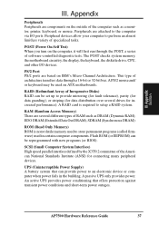
...system that offers protection against transient power conditions and short-term power outages. RAM (Random Access Memory) There are components on ATX motherboards. III. PS/2 Port PS/2 ports are attached to perform an almost limitless variety of RAM such as a monitor, printer, ... through the POST, a series of the American National Standards Institute (ANSI) for increased performance). AP7500 Hardware Reference Guide 37 Appendix Glossary III. The POST checks system memory, the motherboard circuitry, the display, the keyboard, the diskette drive, CPU, and other I /O ports. ...
...system that offers protection against transient power conditions and short-term power outages. RAM (Random Access Memory) There are components on ATX motherboards. III. PS/2 Port PS/2 ports are attached to perform an almost limitless variety of RAM such as a monitor, printer, ... through the POST, a series of the American National Standards Institute (ANSI) for increased performance). AP7500 Hardware Reference Guide 37 Appendix Glossary III. The POST checks system memory, the motherboard circuitry, the display, the keyboard, the diskette drive, CPU, and other I /O ports. ...

