Hardware Reference
Page 2
... Adobe Systems Incorporated. USER'S NOTICE No part of this manual may or may be reproduced, transmitted, transcribed, stored in a retrieval system, or translated into any language in writing by the purchaser for backup purposes, without intent to the owners' benefit, without the express written permission of ASUSTeK COMPUTER INC. ("ASUS"). For previous or updated manuals, BIOS, drivers, or product...
... Adobe Systems Incorporated. USER'S NOTICE No part of this manual may or may be reproduced, transmitted, transcribed, stored in a retrieval system, or translated into any language in writing by the purchaser for backup purposes, without intent to the owners' benefit, without the express written permission of ASUSTeK COMPUTER INC. ("ASUS"). For previous or updated manuals, BIOS, drivers, or product...
Hardware Reference
Page 4
... Power Supply 13 Chassis Panels 14 Circulation System 15 Fan Replacement 15 Fixed Storage Device Tray 16 Fixed Device Bay Cover Clips 16 Fixed Device Bay Cover 16 Fixed Storage Devices 17 Floppy Drive and CD-ROM 17 Floppy Drive and Storage Device Spacers 17 Hot-Swap Trays 18 Hot-Swap Tray Interface 18 Hot-Swap Tray Usage 19 Hot-Swap Tray Front Connections 19 Hot-Swap Tray Connector Board 20 Hot-Swap Tray Rear Connections 20 Motherboard Securing 21 Spacer Mounts 21 4 AP6000 Hardware...
... Power Supply 13 Chassis Panels 14 Circulation System 15 Fan Replacement 15 Fixed Storage Device Tray 16 Fixed Device Bay Cover Clips 16 Fixed Device Bay Cover 16 Fixed Storage Devices 17 Floppy Drive and CD-ROM 17 Floppy Drive and Storage Device Spacers 17 Hot-Swap Trays 18 Hot-Swap Tray Interface 18 Hot-Swap Tray Usage 19 Hot-Swap Tray Front Connections 19 Hot-Swap Tray Connector Board 20 Hot-Swap Tray Rear Connections 20 Motherboard Securing 21 Spacer Mounts 21 4 AP6000 Hardware...
Hardware Reference
Page 6
... void the user's authority to operate this unit not expressly approved by one or more of Communications. 6 AP6000 Hardware Reference Guide WARNING! Canadian Department of Communications Statement This digital apparatus does not exceed the Class B limits for help. These limits are designed to this equipment. The use of shielded cables for connection of the monitor to the graphics card is connected. •...
... void the user's authority to operate this unit not expressly approved by one or more of Communications. 6 AP6000 Hardware Reference Guide WARNING! Canadian Department of Communications Statement This digital apparatus does not exceed the Class B limits for help. These limits are designed to this equipment. The use of shielded cables for connection of the monitor to the graphics card is connected. •...
Hardware Reference
Page 7
... a great deal of time by yourself, it is configured on the ASUS P2B-DS smart motherboard which uses the 440BX chipset from Intel which supports dual Pentium II processors and 100MHz front side Bus in this reference guide are reading the AP6000 server Hardware Reference Guide. Motherboard: ASUS P2B-DS Chassis: ASUS AS-50 Power Supply Pentium II Processor(s) DIMM memory modules Hard Disk Drives Floppy Drive CD-ROM Drive Ethernet Card RAID controller AP6000 Hardware Reference Guide 7 Introduction You are optional and may be...
... a great deal of time by yourself, it is configured on the ASUS P2B-DS smart motherboard which uses the 440BX chipset from Intel which supports dual Pentium II processors and 100MHz front side Bus in this reference guide are reading the AP6000 server Hardware Reference Guide. Motherboard: ASUS P2B-DS Chassis: ASUS AS-50 Power Supply Pentium II Processor(s) DIMM memory modules Hard Disk Drives Floppy Drive CD-ROM Drive Ethernet Card RAID controller AP6000 Hardware Reference Guide 7 Introduction You are optional and may be...
Hardware Reference
Page 8
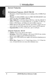
... redundant power supply. • Device Bays: Support for ECC and 100MHz SDRAM. • Super Multi-I/O: (2) PCI Bus Master IDE Ports with Ultra DRAM-33 support, (2) floppy, (2) serial COM ports, (1) parallel, (1) PS/2 keyboard, (1) PS/2 mouse, (2) USB ports, and (1) IrDA connector. • SCSI: Onboard Ultra-II SCSI controller and LVDS to single end converter with support for (1) 3.5inch floppy device, (3) 5.25inch de- vices, (8) hard disk drives in removable aluminum trays. 8 AP6000 Hardware Reference Guide I . Introduction Server Features Motherboard Features: ASUS...
... redundant power supply. • Device Bays: Support for ECC and 100MHz SDRAM. • Super Multi-I/O: (2) PCI Bus Master IDE Ports with Ultra DRAM-33 support, (2) floppy, (2) serial COM ports, (1) parallel, (1) PS/2 keyboard, (1) PS/2 mouse, (2) USB ports, and (1) IrDA connector. • SCSI: Onboard Ultra-II SCSI controller and LVDS to single end converter with support for (1) 3.5inch floppy device, (3) 5.25inch de- vices, (8) hard disk drives in removable aluminum trays. 8 AP6000 Hardware Reference Guide I . Introduction Server Features Motherboard Features: ASUS...
Hardware Reference
Page 9
.... AP6000 Hardware Reference Guide 9 Components I . Static-Sensitive Devices WARNING: Adapters, planars, diskette drives, and disk drives are wrapped in order to or from the existing system before relocating the system. These devices are sensitive to prevent this damage. Avoid touching the solder joints or pins. • If you add a device. Before installing or removing signal cables, ensure that the power cables for the system unit and all power cables...
.... AP6000 Hardware Reference Guide 9 Components I . Static-Sensitive Devices WARNING: Adapters, planars, diskette drives, and disk drives are wrapped in order to or from the existing system before relocating the system. These devices are sensitive to prevent this damage. Avoid touching the solder joints or pins. • If you add a device. Before installing or removing signal cables, ensure that the power cables for the system unit and all power cables...
Hardware Reference
Page 10
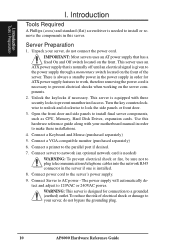
... AP6000 Hardware Reference Guide This server uses an ATX power supply that has a fixed On and Off switch located on the front of electrical shock or damage to your motherboard manual in order for connection to prevent electrical shocks when working on the server components. 2. Connect a VGA-compatible monitor (purchased separately) 6. Turn the key counterclockwise to unlock and clockwise to the parallel port if desired. 7. IMPORTANT: Most servers uses an...
... AP6000 Hardware Reference Guide This server uses an ATX power supply that has a fixed On and Off switch located on the front of electrical shock or damage to your motherboard manual in order for connection to prevent electrical shocks when working on the server components. 2. Connect a VGA-compatible monitor (purchased separately) 6. Turn the key counterclockwise to unlock and clockwise to the parallel port if desired. 7. IMPORTANT: Most servers uses an...
Hardware Reference
Page 11
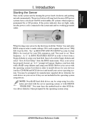
..., hold the "Delete" key and enter BIOS setup in order to boot from the BIOS main menu. AP6000 Hardware Reference Guide 11 Once your ISA expansion card. Reboot your server with a RAID setup diskette and setup your server operating system. Components I . When booting your server for your server has properly booted, an "A:\>" prompt will snap back because ATX power systems have the motherboard or other SCSI device driver diskettes when prompted by turning the power knob clockwise and pushing...
..., hold the "Delete" key and enter BIOS setup in order to boot from the BIOS main menu. AP6000 Hardware Reference Guide 11 Once your ISA expansion card. Reboot your server with a RAID setup diskette and setup your server operating system. Components I . When booting your server for your server has properly booted, an "A:\>" prompt will snap back because ATX power systems have the motherboard or other SCSI device driver diskettes when prompted by turning the power knob clockwise and pushing...

Hardware Reference
Page 12
... the front exterior components of strong rust-resisting metal and covered with wheel Server front side 12 AP6000 Hardware Reference Guide Power LED Hard Drive Activity LED Fan #1 Error (when lit) Fan #2 Error (when lit) Fan #3 Error (when lit) Fan #4 Error (when lit) Fan #5 Error (when lit) LED indicators Floppy Drive CD-ROM Drive Hot Swap Tray Metal Side Access Panel ATX Power Button Fixed Device Bays (for tape or hard disk drives) Metal Door Lock Metal Security Door Stabilizers with a protective ivory...
... the front exterior components of strong rust-resisting metal and covered with wheel Server front side 12 AP6000 Hardware Reference Guide Power LED Hard Drive Activity LED Fan #1 Error (when lit) Fan #2 Error (when lit) Fan #3 Error (when lit) Fan #4 Error (when lit) Fan #5 Error (when lit) LED indicators Floppy Drive CD-ROM Drive Hot Swap Tray Metal Side Access Panel ATX Power Button Fixed Device Bays (for tape or hard disk drives) Metal Door Lock Metal Security Door Stabilizers with a protective ivory...
Hardware Reference
Page 13
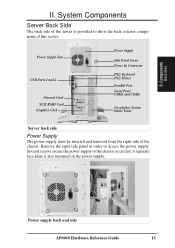
Power Supply Fan USB Ports 1 and 2 Network Card SCSI RAID Card Graphics Card Power Supply Side Panel Screw Power In Connector PS/2 Keyboard PS/2 Mouse Parallel Port Serial Ports COM1 and COM2 Circulation System Outlet Vents Server back side Power Supply The power supply must be inserted and removed from the right side of this server. Power supply back and side AP6000 Hardware Reference Guide 13 Several screws secure the power supply to access the power supply. Components Back Side II. System Components Server Back Side The back...
Power Supply Fan USB Ports 1 and 2 Network Card SCSI RAID Card Graphics Card Power Supply Side Panel Screw Power In Connector PS/2 Keyboard PS/2 Mouse Parallel Port Serial Ports COM1 and COM2 Circulation System Outlet Vents Server back side Power Supply The power supply must be inserted and removed from the right side of this server. Power supply back and side AP6000 Hardware Reference Guide 13 Several screws secure the power supply to access the power supply. Components Back Side II. System Components Server Back Side The back...
Hardware Reference
Page 15
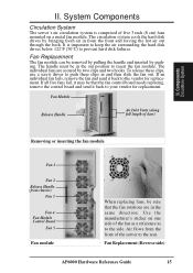
... and two hooks. Use the manufacturer's sticker on a metal fan module. The circulation system cools the hard disk drives by bringing fresh air in and then slide the fan out. If all five fans fail, it back to the side. Air flows from chassis) Fan 3 Fan 4 Fan Module Control Board Fan 5 Fan module When replacing fans, be that the fan rotations are secured by pushing. If an individual fan fails, remove the fan and send it...
... and two hooks. Use the manufacturer's sticker on a metal fan module. The circulation system cools the hard disk drives by bringing fresh air in and then slide the fan out. If all five fans fail, it back to the side. Air flows from chassis) Fan 3 Fan 4 Fan Module Control Board Fan 5 Fan module When replacing fans, be that the fan rotations are secured by pushing. If an individual fan fails, remove the fan and send it...
Hardware Reference
Page 16
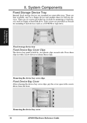
... hard disk drive. II. IRnetmeronvailnFgitxheeddSetvoircaegbeaDyecvoivcerTray 16 AP6000 Hardware Reference Guide System Components Fixed Storage Device Tray Internal fixed storage devices are six screws provided (as circled) for mounting a 4 inch device such as a CD-ROM or tape drive. Press these clips. Components Fixed Device Tray Fixed storage device tray Fixed Device Bay Cover Clips The device bay panel is held by two plastic clips on removable trays. There are mounted on each side. II. Removing the device...
... hard disk drive. II. IRnetmeronvailnFgitxheeddSetvoircaegbeaDyecvoivcerTray 16 AP6000 Hardware Reference Guide System Components Fixed Storage Device Tray Internal fixed storage devices are six screws provided (as circled) for mounting a 4 inch device such as a CD-ROM or tape drive. Press these clips. Components Fixed Device Tray Fixed storage device tray Fixed Device Bay Cover Clips The device bay panel is held by two plastic clips on removable trays. There are mounted on each side. II. Removing the device...
Hardware Reference
Page 17
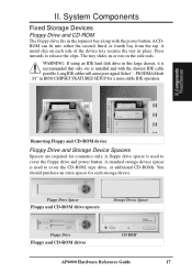
... Floppy Drive Floppy and CD-ROM drives CD-ROM AP6000 Hardware Reference Guide 17 Long IDE cables will cause poor signal. Select "...PIO/DMA Mode : 3/1" in or out on each storage device. II. System Components Fixed Storage Devices Floppy Drive and CD-ROM The floppy drive fits in place. The tray slides in BIOS CHIPSET FEATURES SETUP for a more stable IDE operation. A floppy drive spacer is used to cover the floppy drive and power button...
... Floppy Drive Floppy and CD-ROM drives CD-ROM AP6000 Hardware Reference Guide 17 Long IDE cables will cause poor signal. Select "...PIO/DMA Mode : 3/1" in or out on each storage device. II. System Components Fixed Storage Devices Floppy Drive and CD-ROM The floppy drive fits in place. The tray slides in BIOS CHIPSET FEATURES SETUP for a more stable IDE operation. A floppy drive spacer is used to cover the floppy drive and power button...
Hardware Reference
Page 18
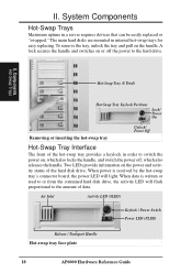
... power off the power to the hard drive. The main hard disks are mounted in a server requires devices that can be easily replaced or "swapped." When data is received by the hot-swap tray's connector board, the power LED will flash proportional to or from the contained hard disk drive, the activity LED will light. II. Air Inlet Activity LED (SLED) Keylock / Power Switch Power LED (PLED) Release / Transport Handle Hot-swap tray face plate 18 AP6000 Hardware Reference Guide II. To remove...
... power off the power to the hard drive. The main hard disks are mounted in a server requires devices that can be easily replaced or "swapped." When data is received by the hot-swap tray's connector board, the power LED will flash proportional to or from the contained hard disk drive, the activity LED will light. II. Air Inlet Activity LED (SLED) Keylock / Power Switch Power LED (PLED) Release / Transport Handle Hot-swap tray face plate 18 AP6000 Hardware Reference Guide II. To remove...
Hardware Reference
Page 19
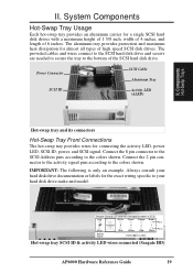
... opposite power & SCSI Red White Green Orange Brown Unused 8 4 2 1 Black Activity Signal Blue Yellow Red Black SCSI Address (ID#) Pin 1 Pin 2 Hot-swap tray SCSI ID & activity LED wires connected (Seagate HD) AP6000 Hardware Reference Guide 19 Connect the 2 pin connector to the activity signal pins according to your hard disk drive documentation or labels for almost all types of 6 inches. The provided cables and wires connect to the SCSI hard disk drive and...
... opposite power & SCSI Red White Green Orange Brown Unused 8 4 2 1 Black Activity Signal Blue Yellow Red Black SCSI Address (ID#) Pin 1 Pin 2 Hot-swap tray SCSI ID & activity LED wires connected (Seagate HD) AP6000 Hardware Reference Guide 19 Connect the 2 pin connector to the activity signal pins according to your hard disk drive documentation or labels for almost all types of 6 inches. The provided cables and wires connect to the SCSI hard disk drive and...
Hardware Reference
Page 20
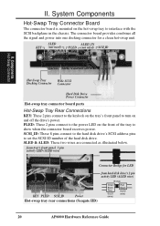
... ALED (wire) 20 AP6000 Hardware Reference Guide SLED KEY (not used) ALED_IN PLED (not used) SCSI_ID II. SCSI_ID: These 8 pins connect to the hard disk drive's SCSI address pins to set the SCSI ID number of the tray to the power LED on the tray's front panel to interface with the SCSI backplane in the chassis. Components Hot-Swap Connector Hot-Swap Tray Wide SCSI Docking Connector Connector Hard Disk Drive Power Connector Hot-swap tray connector board parts Hot-Swap Tray Rear Connections KEY: These 2 pins connect to the keylock on...
... ALED (wire) 20 AP6000 Hardware Reference Guide SLED KEY (not used) ALED_IN PLED (not used) SCSI_ID II. SCSI_ID: These 8 pins connect to the hard disk drive's SCSI address pins to set the SCSI ID number of the tray to the power LED on the tray's front panel to interface with the SCSI backplane in the chassis. Components Hot-Swap Connector Hot-Swap Tray Wide SCSI Docking Connector Connector Hard Disk Drive Power Connector Hot-swap tray connector board parts Hot-Swap Tray Rear Connections KEY: These 2 pins connect to the keylock on...
Hardware Reference
Page 22
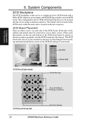
... setting of this server is located on each SCSI board. Top Half Bottom Half SCSI board placement Notch Out (top) Four SCSI Board Docking Connectors SCSI board front side Notch In (bottom) 22 AP6000 Hardware Reference Guide This configuration allows Wide-SCSI hard disk drives to be removed to properly seat the SCSI boards into the server using a common connector. The female end is located on the SCSI board, while the male end is comprised of two SCSI boards with a Wide-SCSI connector, power...
... setting of this server is located on each SCSI board. Top Half Bottom Half SCSI board placement Notch Out (top) Four SCSI Board Docking Connectors SCSI board front side Notch In (bottom) 22 AP6000 Hardware Reference Guide This configuration allows Wide-SCSI hard disk drives to be removed to properly seat the SCSI boards into the server using a common connector. The female end is located on the SCSI board, while the male end is comprised of two SCSI boards with a Wide-SCSI connector, power...
Hardware Reference
Page 24
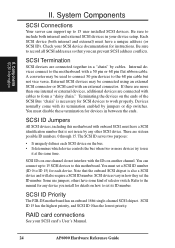
... any other SCSI device. Be sure to form a "daisy chain." System Components SCSI Connections Your server can prevent SCSI address conflicts. Devices normally come with a 50 pin or 68 pin flat ribbon cable. You must have some kind of the SCSI Bus "chain" is not in your SCSI card's User's Manual. 24 AP6000 Hardware Reference Guide II. Check your SCSI device documentation for SCSI devices to the manual for devices in how they set the ID number. Refer...
... any other SCSI device. Be sure to form a "daisy chain." System Components SCSI Connections Your server can prevent SCSI address conflicts. Devices normally come with a 50 pin or 68 pin flat ribbon cable. You must have some kind of the SCSI Bus "chain" is not in your SCSI card's User's Manual. 24 AP6000 Hardware Reference Guide II. Check your SCSI device documentation for SCSI devices to the manual for devices in how they set the ID number. Refer...
Hardware Reference
Page 26
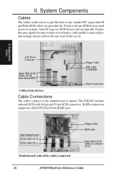
... Power Connector 68pin Wide SCSI Cables (SCSI hard disk drives) Floppy Cable IDE Cable (CD-ROM) Panel Connectors Cables from devices Cable Connections The cables connect to the motherboard as the one used in server systems. Your PC may use SCSI devices but are typically 50 pins. RAID connections require the ASUS PCI-DA2100A RAID card. Because signals become weaker over distance, cable quality is just like that of any standard PC expect that 68 pin Wide-SCSI cables are provided for onboard SCSI 26 AP6000 Hardware Reference Guide...
... Power Connector 68pin Wide SCSI Cables (SCSI hard disk drives) Floppy Cable IDE Cable (CD-ROM) Panel Connectors Cables from devices Cable Connections The cables connect to the motherboard as the one used in server systems. Your PC may use SCSI devices but are typically 50 pins. RAID connections require the ASUS PCI-DA2100A RAID card. Because signals become weaker over distance, cable quality is just like that of any standard PC expect that 68 pin Wide-SCSI cables are provided for onboard SCSI 26 AP6000 Hardware Reference Guide...
Hardware Reference
Page 29
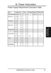
Power Req. Power Information Power Supply Requirement Calculation Table Item Volts Amp x Qty. = TotalAmp Watts (5V) Watts (12V) Total Motherboard Power 209.55 3.6 Hard Drive 5.0V 1.3 x = 12V 1.5 x = CD-ROM 5.0V x = 12V x = Tape Drive 5.0V x = 12V x = Floppy Drive 5.0V x = 12V x = System Fans 5.0V x = 12V 0.3 x = 0.6 7.2 Other 3.3V x = 5.0V x = 12V x = Total Power III. Table AP6000 Hardware Reference Guide 29 Power Info. III.
Power Req. Power Information Power Supply Requirement Calculation Table Item Volts Amp x Qty. = TotalAmp Watts (5V) Watts (12V) Total Motherboard Power 209.55 3.6 Hard Drive 5.0V 1.3 x = 12V 1.5 x = CD-ROM 5.0V x = 12V x = Tape Drive 5.0V x = 12V x = Floppy Drive 5.0V x = 12V x = System Fans 5.0V x = 12V 0.3 x = 0.6 7.2 Other 3.3V x = 5.0V x = 12V x = Total Power III. Table AP6000 Hardware Reference Guide 29 Power Info. III.


