
AP2400R 2U Server User Manual English Edition
Page 2
... or updated manuals, BIOS, drivers, or product release information, contact ASUS at http://www.asus.com.tw or through any means, except documentation kept by the digit before and after the period of the manual revision number. Manual revisions are used only for each product design represented by the purchaser for backup purposes, without intent to infringe. Product Name: AP2400R (ASUSPRO 2400R) Manual...
... or updated manuals, BIOS, drivers, or product release information, contact ASUS at http://www.asus.com.tw or through any means, except documentation kept by the digit before and after the period of the manual revision number. Manual revisions are used only for each product design represented by the purchaser for backup purposes, without intent to infringe. Product Name: AP2400R (ASUSPRO 2400R) Manual...
AP2400R 2U Server User Manual English Edition
Page 4
... and, if not installed and used in accordance with FCC regulations. This class B digital apparatus complies with FCC Rules Part 15. Safeguards FCC/CDC Statements Federal Communications Commission Statement This device complies with Canadian ICES-003. 4 Introduction: About This Manual WARNING! If this unit not expressly approved by one or more of Communications. Operation is no guarantee...
... and, if not installed and used in accordance with FCC regulations. This class B digital apparatus complies with FCC Rules Part 15. Safeguards FCC/CDC Statements Federal Communications Commission Statement This device complies with Canadian ICES-003. 4 Introduction: About This Manual WARNING! If this unit not expressly approved by one or more of Communications. Operation is no guarantee...
AP2400R 2U Server User Manual English Edition
Page 5
.... • If the power supply is powered on this server must be hot. Check whether the fans are connecting or disconnecting any damage is detected, contact your server, carefully read all the manuals included with the server package. • Before using the server, make sure all cables are correctly connected and the power cables are unplugged. • Avoid dust, humidity, and temperature extremes. AP2400R Hardware Reference Guide 5 If any devices. Electrical Safety Safet...
.... • If the power supply is powered on this server must be hot. Check whether the fans are connecting or disconnecting any damage is detected, contact your server, carefully read all the manuals included with the server package. • Before using the server, make sure all cables are correctly connected and the power cables are unplugged. • Avoid dust, humidity, and temperature extremes. AP2400R Hardware Reference Guide 5 If any devices. Electrical Safety Safet...
AP2400R 2U Server User Manual English Edition
Page 6
... • If you add a device. • Use one hand, when possible, to connect or disconnect signal cables to prevent a possible shock from touching two surfaces with a three-wire power cable and plug for the user's safety. IMPORTANT Motherboards, adapters, and disk drives are sensitive to avoid ...installing or removing signal cables, ensure that the power cables for the system unit and all power cables from the existing system before the signal cables are connected. These devices are wrapped in its antistatic bag, touch it while handling the device. • Do not remove the device...
... • If you add a device. • Use one hand, when possible, to connect or disconnect signal cables to prevent a possible shock from touching two surfaces with a three-wire power cable and plug for the user's safety. IMPORTANT Motherboards, adapters, and disk drives are sensitive to avoid ...installing or removing signal cables, ensure that the power cables for the system unit and all power cables from the existing system before the signal cables are connected. These devices are wrapped in its antistatic bag, touch it while handling the device. • Do not remove the device...
AP2400R 2U Server User Manual English Edition
Page 7
... Conventions 11 Symbols 11 Package Contents 12 Standard Components 12 Optional Components 12 Chapter 1 System Overview 13 Features 14 Chassis: ASUS AR-20 14 Motherboard: ASUS CUR-DLSR 14 Front Panel 15 Back Panel 15 Power Button and System LEDs 16 LED Information 17 Hard Drive Power & Status LEDs 17 System Reset Button 17 Programmable Message LED 17 Fan Fail or High Temperature LED 17 Power Supply Failure LED 17 Hard Disk Activity LED 17 Power ON LED 17 System Power Button 17 AP2400R Hardware Reference Guide 7
... Conventions 11 Symbols 11 Package Contents 12 Standard Components 12 Optional Components 12 Chapter 1 System Overview 13 Features 14 Chassis: ASUS AR-20 14 Motherboard: ASUS CUR-DLSR 14 Front Panel 15 Back Panel 15 Power Button and System LEDs 16 LED Information 17 Hard Drive Power & Status LEDs 17 System Reset Button 17 Programmable Message LED 17 Fan Fail or High Temperature LED 17 Power Supply Failure LED 17 Hard Disk Activity LED 17 Power ON LED 17 System Power Button 17 AP2400R Hardware Reference Guide 7
AP2400R 2U Server User Manual English Edition
Page 8
Contents Chapter 2 Basic Operation 19 Getting Started 20 Connect a Monitor 20 Connect Power Cords 20 Turn the Power ON 20 Check Power LED 20 Chapter 3 Hardware Setup 21 Opening the Chassis Cover 22 Under the Chassis Cover 23 Internal Components 24 Motherboard Placement 25 Central Processing Unit (CPU 26 CPU Heatsink 27 CPU Terminator 28 Cooling Fans 29 System Memory 30 Riser Card / Expansion Card 31 SCSI Backplane 32 Connecting Cables 33 Connecting Cables 34 SCSI Hard Disk Drives 35 Floppy Drive 37 8 Introduction: About This Manual
Contents Chapter 2 Basic Operation 19 Getting Started 20 Connect a Monitor 20 Connect Power Cords 20 Turn the Power ON 20 Check Power LED 20 Chapter 3 Hardware Setup 21 Opening the Chassis Cover 22 Under the Chassis Cover 23 Internal Components 24 Motherboard Placement 25 Central Processing Unit (CPU 26 CPU Heatsink 27 CPU Terminator 28 Cooling Fans 29 System Memory 30 Riser Card / Expansion Card 31 SCSI Backplane 32 Connecting Cables 33 Connecting Cables 34 SCSI Hard Disk Drives 35 Floppy Drive 37 8 Introduction: About This Manual
AP2400R 2U Server User Manual English Edition
Page 10
The basic operation includes connecting the cables and powering on the internal components and how to install them. 10 Introduction: About This Manual Introduction: About This Guide This part contains an introduction on the contents of this document that you have to get started with hardware knowledge of the AP2400R server. It also lists the items included in the system package. 2. It also gives detailed information...
The basic operation includes connecting the cables and powering on the internal components and how to install them. 10 Introduction: About This Manual Introduction: About This Guide This part contains an introduction on the contents of this document that you have to get started with hardware knowledge of the AP2400R server. It also lists the items included in the system package. 2. It also gives detailed information...
AP2400R 2U Server User Manual English Edition
Page 12
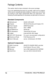
... processor configuration R-20 Rackmount Kit server, motherboard, CD-ROM Optional Components RAID Controller Processor Memory Hard Drive ASUS PCI-DA2200 RAID controller Dual Pentium® III up to 1GHz Up to 4GB registered ECC SDRAM Up to prepare all the server components before starting. Standard Components Motherboard Chassis Power Supply Floppy Drive CD-ROM Drive PCI Expansion Cables S370 CPU Terminator Rackmount Rails User's Manuals ASUS CUR-DLSR AR-20 2U Rackmount Chassis (19") 280W Redundant Slim 1.44MB ASUS 50x Three 64-bit PCI slots Internal SCSI, IDE, floppy For use...
... processor configuration R-20 Rackmount Kit server, motherboard, CD-ROM Optional Components RAID Controller Processor Memory Hard Drive ASUS PCI-DA2200 RAID controller Dual Pentium® III up to 1GHz Up to 4GB registered ECC SDRAM Up to prepare all the server components before starting. Standard Components Motherboard Chassis Power Supply Floppy Drive CD-ROM Drive PCI Expansion Cables S370 CPU Terminator Rackmount Rails User's Manuals ASUS CUR-DLSR AR-20 2U Rackmount Chassis (19") 280W Redundant Slim 1.44MB ASUS 50x Three 64-bit PCI slots Internal SCSI, IDE, floppy For use...
AP2400R 2U Server User Manual English Edition
Page 14
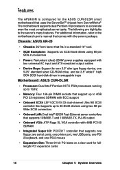
... cables • Device Bays: Support for one 3.5" slim type floppy device, one PS/2 mouse • Expansion Slot: Three 64-bit PCI slots on a riser card for the ASUS CUR-DLSR smart motherboard that uses the ServerSetTM chipset from ServerWorks®. Chassis: ASUS AR-20 • Chassis: 2U form factor that fits in a standard 19" rack • SCSI Backplane: Supports six SCSI hard drives using two 68-pin Wide SCSI connectors • Onboard LAN: Dual Intel® 82559 Fast-Ethernet server controllers...
... cables • Device Bays: Support for one 3.5" slim type floppy device, one PS/2 mouse • Expansion Slot: Three 64-bit PCI slots on a riser card for the ASUS CUR-DLSR smart motherboard that uses the ServerSetTM chipset from ServerWorks®. Chassis: ASUS AR-20 • Chassis: 2U form factor that fits in a standard 19" rack • SCSI Backplane: Supports six SCSI hard drives using two 68-pin Wide SCSI connectors • Onboard LAN: Dual Intel® 82559 Fast-Ethernet server controllers...

AP2400R 2U Server User Manual English Edition
Page 15
... Connectors 3. Serial Port (COM2) 7. Serial Port (COM1) 11. PS/2 Mouse Port 4. Three PCI Expansion Slots 8. Power Supply Power LED 9. Video-Out (VGA) Port 12. The power button and the system LED indicators are also located on the front panel (see next page for descriptions). LAN Ports 1 & 2 (RJ-45) 13. Very High-Density SCSI Connector AP2400R Hardware Reference Guide 15 USB Ports 1 and 2 5. Parallel Port 6. PS/2 Keyboard Port 10. System LEDs ID0 ID3 ID1 ID4 ID2 ID5 Hard Drive Bays CD-ROM Drive Floppy Drive Hard Drive Bays Back Panel The server...
... Connectors 3. Serial Port (COM2) 7. Serial Port (COM1) 11. PS/2 Mouse Port 4. Three PCI Expansion Slots 8. Power Supply Power LED 9. Video-Out (VGA) Port 12. The power button and the system LED indicators are also located on the front panel (see next page for descriptions). LAN Ports 1 & 2 (RJ-45) 13. Very High-Density SCSI Connector AP2400R Hardware Reference Guide 15 USB Ports 1 and 2 5. Parallel Port 6. PS/2 Keyboard Port 10. System LEDs ID0 ID3 ID1 ID4 ID2 ID5 Hard Drive Bays CD-ROM Drive Floppy Drive Hard Drive Bays Back Panel The server...

AP2400R 2U Server User Manual English Edition
Page 16
Fan Fail or High Temperature LED 10. Power Supply Status & Failure LED 11. System Power Button 16 Chapter 1: System Overview Hard Drive Power & Status LEDs 7. Programmable Message LED 9. Hard Disk Activity LED 12. Hard Drive Power & Status LEDs 4-6. Power ON LED 13. Power Button and System LEDs The front panel includes system LEDs to indicate fan and thermal status, hard disk status, and system power status. 1 4 2 5 3 6 7 8 9 10 11 12 13 1-3. System Reset Button 8.
Fan Fail or High Temperature LED 10. Power Supply Status & Failure LED 11. System Power Button 16 Chapter 1: System Overview Hard Drive Power & Status LEDs 7. Programmable Message LED 9. Hard Disk Activity LED 12. Hard Drive Power & Status LEDs 4-6. Power ON LED 13. Power Button and System LEDs The front panel includes system LEDs to indicate fan and thermal status, hard disk status, and system power status. 1 4 2 5 3 6 7 8 9 10 11 12 13 1-3. System Reset Button 8.
AP2400R 2U Server User Manual English Edition
Page 17
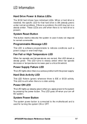
... such a power outage or event warnings. Power Supply Failure LED This LED lights when there is IDE or SCSI activity. Hard Disk Activity LED This LED flickers (green) whenever there is a serious problem with the power supply. Programmable Message LED This LED is connected to normal commands. This LED is unlit when there is present. System Power Button The system power button is software programmable to steady amber when fan speeds decrease or temperatures increase past a critical threshold. System Reset Button This button resets (reboots) the system...
... such a power outage or event warnings. Power Supply Failure LED This LED lights when there is IDE or SCSI activity. Hard Disk Activity LED This LED flickers (green) whenever there is a serious problem with the power supply. Programmable Message LED This LED is connected to normal commands. This LED is unlit when there is present. System Power Button The system power button is software programmable to steady amber when fan speeds decrease or temperatures increase past a critical threshold. System Reset Button This button resets (reboots) the system...

AP2400R 2U Server User Manual English Edition
Page 20
Turn the Power ON Power Button Power ON the server by plugging the 15-pin video cable to two separate power sockets. Hard Drive Warning (Amber) Fan/Temp Power LED LED Check Power LED After powering on the back of the power cords, connect each one to a different source, for example, two separate UPS connected to the video-out port (blue) on the back of the server. Follow these steps when starting the server. Connect a Monitor Video-Out (VGA) Port Connect a VGA-compatible monitor by pressing...
Turn the Power ON Power Button Power ON the server by plugging the 15-pin video cable to two separate power sockets. Hard Drive Warning (Amber) Fan/Temp Power LED LED Check Power LED After powering on the back of the power cords, connect each one to a different source, for example, two separate UPS connected to the video-out port (blue) on the back of the server. Follow these steps when starting the server. Connect a Monitor Video-Out (VGA) Port Connect a VGA-compatible monitor by pressing...

AP2400R 2U Server User Manual English Edition
Page 22
Opening the Chassis Cover The AP2400R chassis is a rotating lock that connect to the inner side of the back panel. Unlocking the Cover To unlock the cover, turn the rotating lock clockwise until the triangle mark points to disengage the locking tabs before lifting up the cover. 22 Chapter 3: Hardware Setup Triangle Mark Rotating Lock CLOSE OPEN Removing the Cover Slide the top cover toward the front for...
Opening the Chassis Cover The AP2400R chassis is a rotating lock that connect to the inner side of the back panel. Unlocking the Cover To unlock the cover, turn the rotating lock clockwise until the triangle mark points to disengage the locking tabs before lifting up the cover. 22 Chapter 3: Hardware Setup Triangle Mark Rotating Lock CLOSE OPEN Removing the Cover Slide the top cover toward the front for...
AP2400R 2U Server User Manual English Edition
Page 24
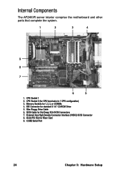
Memory Sockets for standard 5 1/4" CD-ROM Drive 5. IDE Connector for 1, 2, 3, or 4 DIMMs 4. COM2 Serial Port 24 Chapter 3: Hardware Setup Internal Components The AP2400R server interior comprise the motherboard and other parts that complete the system. 1 2 3 4 9 8 7 6 5 1. SCSI Cable for Riser Card 9. External Very High Density Connector Interface (VHDCI) SCSI Connector 8. 64-bit PCI Slot for Hot Swap SCA SCSI Connectors 7. CPU Socket 1 2. CPU Socket 2 (for CPU terminator in 1 CPU configuration) 3. Slim Floppy Drive Cable 6.
Memory Sockets for standard 5 1/4" CD-ROM Drive 5. IDE Connector for 1, 2, 3, or 4 DIMMs 4. COM2 Serial Port 24 Chapter 3: Hardware Setup Internal Components The AP2400R server interior comprise the motherboard and other parts that complete the system. 1 2 3 4 9 8 7 6 5 1. SCSI Cable for Riser Card 9. External Very High Density Connector Interface (VHDCI) SCSI Connector 8. 64-bit PCI Slot for Hot Swap SCA SCSI Connectors 7. CPU Socket 1 2. CPU Socket 2 (for CPU terminator in 1 CPU configuration) 3. Slim Floppy Drive Cable 6.
AP2400R 2U Server User Manual English Edition
Page 25
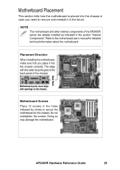
The edge with openings on the chassis. Motherboard ports must align with the external ports goes to remove and reinstall it into the chassis in case you place it in the future. Placement Direction When installing the motherboard, make sure that you need to the back panel of the AP2400R server are already installed as indicated in the section "Internal Components". Back Panel AP2400R Hardware Reference Guide 25 Doing so...
The edge with openings on the chassis. Motherboard ports must align with the external ports goes to remove and reinstall it into the chassis in case you place it in the future. Placement Direction When installing the motherboard, make sure that you need to the back panel of the AP2400R server are already installed as indicated in the section "Internal Components". Back Panel AP2400R Hardware Reference Guide 25 Doing so...
AP2400R 2U Server User Manual English Edition
Page 30
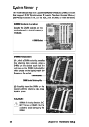
DIMM Sockets Location Locate the DIMM sockets on the motherboard to avoid damaging the DIMM. 30 Chapter 3: Hardware Setup DO NOT force a DIMM into the socket to install memory modules. 4 DIMM Sockets DIMM Installation (1) Unlock a DIMM socket by white circles on the figure) match the breaks on the socket. CAUTION: DIMMs fit in place. DIMM Notches DIMM Socket Retaining Clip (2) Carefully insert the DIMM on the socket until the retaining clips...
DIMM Sockets Location Locate the DIMM sockets on the motherboard to avoid damaging the DIMM. 30 Chapter 3: Hardware Setup DO NOT force a DIMM into the socket to install memory modules. 4 DIMM Sockets DIMM Installation (1) Unlock a DIMM socket by white circles on the figure) match the breaks on the socket. CAUTION: DIMMs fit in place. DIMM Notches DIMM Socket Retaining Clip (2) Carefully insert the DIMM on the socket until the retaining clips...

AP2400R 2U Server User Manual English Edition
Page 31
...-bit PCI card slots for PCI expansion cards. PCI Cage PCI Connector PCI Card Connector Mounted Riser Installing an Expansion Card Carefully insert the golden fingers of the riser card into the PCI slot on the riser card. Expansion Card PCI Slot Riser Card AP2400R Hardware Reference Guide 31 The PCI cage then installs on the chassis in such a way that will at the same time insert the golden fingers of the PCI expansion card into the single PCI slot on the PCI cage. The slot requires a PCI riser card to accommodate PCI expansion cards...
...-bit PCI card slots for PCI expansion cards. PCI Cage PCI Connector PCI Card Connector Mounted Riser Installing an Expansion Card Carefully insert the golden fingers of the riser card into the PCI slot on the riser card. Expansion Card PCI Slot Riser Card AP2400R Hardware Reference Guide 31 The PCI cage then installs on the chassis in such a way that will at the same time insert the golden fingers of the PCI expansion card into the single PCI slot on the PCI cage. The slot requires a PCI riser card to accommodate PCI expansion cards...

AP2400R 2U Server User Manual English Edition
Page 32
... failure, and fan failure. The LED connector on the backplane connects to the front panel LEDs to left board LED out to front panel SCSI Connector (for terminator) (1) SMB in the system chassis. You do not need to allow easy connection or removal of six. SCSI Backplane The two SCSI backplane supports three Ultra160 SCA SCSI hard disks each for a total of SCA SCSI hard disks. The backplane design incorporates a hot-swap feature to remove the backplane when installing components or connecting cables. 32 Chapter 3: Hardware Setup...
... failure, and fan failure. The LED connector on the backplane connects to the front panel LEDs to left board LED out to front panel SCSI Connector (for terminator) (1) SMB in the system chassis. You do not need to allow easy connection or removal of six. SCSI Backplane The two SCSI backplane supports three Ultra160 SCA SCSI hard disks each for a total of SCA SCSI hard disks. The backplane design incorporates a hot-swap feature to remove the backplane when installing components or connecting cables. 32 Chapter 3: Hardware Setup...
AP2400R 2U Server User Manual English Edition
Page 35
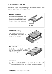
... sure that the SCSI cable is connected to release the tray, then slide the tray out of the HDD bays is secured to the section "Connecting Cables". SCSI Hard Disk Drives The system comes with four screws as shown. AP2400R Hardware Reference Guide 35 Tray Levers SCSI HDD Mounting Place the SCSI hard disk drive to make a total of six. Flip open the tray levers to the motherboard and the...
... sure that the SCSI cable is connected to release the tray, then slide the tray out of the HDD bays is secured to the section "Connecting Cables". SCSI Hard Disk Drives The system comes with four screws as shown. AP2400R Hardware Reference Guide 35 Tray Levers SCSI HDD Mounting Place the SCSI hard disk drive to make a total of six. Flip open the tray levers to the motherboard and the...


