User Guide
Page 3
... the front panel assembly 2-14 2.6 5.25-inch drives 2-15 2.7 Hard disk drives 2-18 2.7.1 Installing a hot-swap SCSI HDD 2-18 2.7.2 Installing an IDE HDD 2-20 2.8 Expansion cards 2-25 2.8.1 Installing a standard size expansion card 2-25 2.8.2 Installing a long expansion card 2-27 2.8.3 Removing an expansion...
... the front panel assembly 2-14 2.6 5.25-inch drives 2-15 2.7 Hard disk drives 2-18 2.7.1 Installing a hot-swap SCSI HDD 2-18 2.7.2 Installing an IDE HDD 2-20 2.8 Expansion cards 2-25 2.8.1 Installing a standard size expansion card 2-25 2.8.2 Installing a long expansion card 2-27 2.8.3 Removing an expansion...
User Guide
Page 5
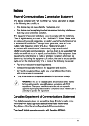
... technician for compliance could void the user's authority to operate this unit not expressly approved by one or more of the monitor to the graphics card is no guarantee that interference will not occur in accordance with manufacturer's instructions, may cause undesired operation. However, there is required to radio communications. Notices...
... technician for compliance could void the user's authority to operate this unit not expressly approved by one or more of the monitor to the graphics card is no guarantee that interference will not occur in accordance with manufacturer's instructions, may cause undesired operation. However, there is required to radio communications. Notices...
User Guide
Page 10
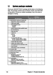
Contact your ASUS AP1720-E1 package with : • ASUS PC-DL Deluxe motherboard • 450W power supply • SCSI backplane board (2 pieces) (1 piece) • ASUS U160/320 SCSI card/SCSI cable • 52x CD-ROM drive • floppy disk drive • chassis fan • HDD fan... keys ( 2 pcs.) 5) Bundled CDs • AP1720-E1 support CD • ASWM software CD • TrendMicro® ServerProtect® CD 6) Documentation • ASUS AP1720-E1 user guide • ASUS PC-DL Deluxe user guide 7) Optional items • ASUS AK25 rackmount rail kit • AK25 internal HDD cage...
Contact your ASUS AP1720-E1 package with : • ASUS PC-DL Deluxe motherboard • 450W power supply • SCSI backplane board (2 pieces) (1 piece) • ASUS U160/320 SCSI card/SCSI cable • 52x CD-ROM drive • floppy disk drive • chassis fan • HDD fan... keys ( 2 pcs.) 5) Bundled CDs • AP1720-E1 support CD • ASWM software CD • TrendMicro® ServerProtect® CD 6) Documentation • ASUS AP1720-E1 user guide • ASUS PC-DL Deluxe user guide 7) Optional items • ASUS AK25 rackmount rail kit • AK25 internal HDD cage...
User Guide
Page 14
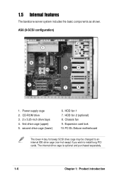
... may be changed to an internal IDE drive cage (non-hot swap) if you wish to install long PCI cards. 1.5 Internal features The barebone server system includes the basic components as shown. Expansion card lock 10. HDD fan 1 7. Power supply cage 2. AS8 (8-SCSI configuration) 1 8 10 2 3 6 4 9 7 5 1. CD-ROM drive 3. 2 x 5.25-inch drive bays...
... may be changed to an internal IDE drive cage (non-hot swap) if you wish to install long PCI cards. 1.5 Internal features The barebone server system includes the basic components as shown. Expansion card lock 10. HDD fan 1 7. Power supply cage 2. AS8 (8-SCSI configuration) 1 8 10 2 3 6 4 9 7 5 1. CD-ROM drive 3. 2 x 5.25-inch drive bays...
User Guide
Page 16
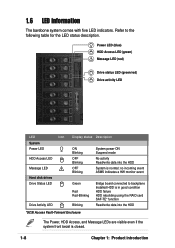
... Message LED ! Power LED (blue) HDD Access LED (green) ! Refer to backplane Installed HDD is in good condition HDD failure HDD rebuilding using the RAID card SAF-TE* function Read/write data into the HDD System is closed. 1-8 Chapter 1: Product introduction 1.6 LED information The barebone system comes with five LED indicators...
... Message LED ! Power LED (blue) HDD Access LED (green) ! Refer to backplane Installed HDD is in good condition HDD failure HDD rebuilding using the RAID card SAF-TE* function Read/write data into the HDD System is closed. 1-8 Chapter 1: Product introduction 1.6 LED information The barebone system comes with five LED indicators...
User Guide
Page 19
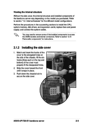
... the succeeding sections to remove some of the chassis. You may need to install the CPU, system memory, disk drives, and expansion cards; Refer to secure the side cover. 1 2 3 ASUS AP1720-E1 barebone server 2-3 Push down the chassis lock to section "2.10 Removable components" for the different model configurations. All the six hooks (three...
... the succeeding sections to remove some of the chassis. You may need to install the CPU, system memory, disk drives, and expansion cards; Refer to secure the side cover. 1 2 3 ASUS AP1720-E1 barebone server 2-3 Push down the chassis lock to section "2.10 Removable components" for the different model configurations. All the six hooks (three...
User Guide
Page 41
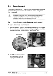
...and damage to unplug the power cord before installing or removing expansion cards. Carefully install an expansion card making sure that it is designed with a screwless expansion slot frame on the slot. 2.8 Expansion cards The chassis is properly seated on the rear panel. This design... remove an expansion card in less steps. Remove the plastic card lock opposite the slot where you to install the expansion card. Release the card lock by pressing the center tabs and pushing outward. Card lock tabs 2. Set the card lock aside for later use. ASUS AP1720-E1 barebone server 2-25...
...and damage to unplug the power cord before installing or removing expansion cards. Carefully install an expansion card making sure that it is designed with a screwless expansion slot frame on the slot. 2.8 Expansion cards The chassis is properly seated on the rear panel. This design... remove an expansion card in less steps. Remove the plastic card lock opposite the slot where you to install the expansion card. Release the card lock by pressing the center tabs and pushing outward. Card lock tabs 2. Set the card lock aside for later use. ASUS AP1720-E1 barebone server 2-25...
User Guide
Page 42
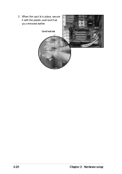
3. When the card is in place, secure it with the plastic card lock that you removed earlier. Card lock tab 2-26 Chapter 2: Hardware setup
3. When the card is in place, secure it with the plastic card lock that you removed earlier. Card lock tab 2-26 Chapter 2: Hardware setup
User Guide
Page 43
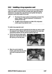
... the slot opening on the rear panel. 3. The internal drive cage is level with long card guides that keep the expansion cards firmly seated on installing the drive cage. 2. ASUS AP1720-E1 barebone server 2-27 See section "Chapter 3 Optional components" for later use. 2. Set the card lock aside for instructions on the slots. 1. Remove the plastic...
... the slot opening on the rear panel. 3. The internal drive cage is level with long card guides that keep the expansion cards firmly seated on installing the drive cage. 2. ASUS AP1720-E1 barebone server 2-27 See section "Chapter 3 Optional components" for later use. 2. Set the card lock aside for instructions on the slots. 1. Remove the plastic...
User Guide
Page 44
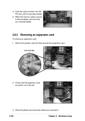
Push the card connector into the PCI slot until it is in place, secure it with the plastic card lock that secures the expansion card. Remove the plastic card lock that you removed it out of the slot. 3. Firmly hold the expansion card and pull it . 2-28 Chapter 2: Hardware setup Place the plastic card lock back where you removed earlier. 2.8.3 Removing an expansion card To remove an expansion card: 1. Card lock tabs 2. 4. When the card is securely seated. 5.
Push the card connector into the PCI slot until it is in place, secure it with the plastic card lock that secures the expansion card. Remove the plastic card lock that you removed it out of the slot. 3. Firmly hold the expansion card and pull it . 2-28 Chapter 2: Hardware setup Place the plastic card lock back where you removed earlier. 2.8.3 Removing an expansion card To remove an expansion card: 1. Card lock tabs 2. 4. When the card is securely seated. 5.
User Guide
Page 46
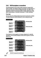
... hot swap drive trays. The LEDs on the backplane connect to the front panel LEDs to 8. This side includes four SCSI connectors for the SCSI card. 2-30 Chapter 2: Hardware setup First backplane Disk drive 1 SCSI ID = 0 HDD status LEDs Disk drive 2 SCSI ID = 1 Disk drive 3 SCSI ID = 2 HDD activity LEDs Disk...
... hot swap drive trays. The LEDs on the backplane connect to the front panel LEDs to 8. This side includes four SCSI connectors for the SCSI card. 2-30 Chapter 2: Hardware setup First backplane Disk drive 1 SCSI ID = 0 HDD status LEDs Disk drive 2 SCSI ID = 1 Disk drive 3 SCSI ID = 2 HDD activity LEDs Disk...
User Guide
Page 47
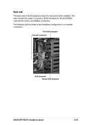
This side includes the power connectors, SCSI interfaces for the SCSI/RAID card and terminator, and SMBus connectors. The following picture shows a two-backplane configuration in a cascade connection. First SCSI backplane Cascade connection SCSI terminator Second SCSI backplane ASUS AP1720-E1 barebone server 2-31 Back side The back side of SCSI backplane faces the rear panel when installed.
This side includes the power connectors, SCSI interfaces for the SCSI/RAID card and terminator, and SMBus connectors. The following picture shows a two-backplane configuration in a cascade connection. First SCSI backplane Cascade connection SCSI terminator Second SCSI backplane ASUS AP1720-E1 barebone server 2-31 Back side The back side of SCSI backplane faces the rear panel when installed.
User Guide
Page 48
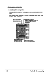
One-backplane configuration In a one-backplane configuration: • the upper SCSI interface of the backplane connects to the SCSI/RAID card • a SCSI multi-mode terminator (LVD/SE) is connected to the lower SCSI interface of the backplane Power connectors (connect power plugs from the power supply) Fan connector (for HDD fan) SMBus connector (upper 6-1 pins) (connects the SMB cable from the motherboard) 68-pin SCSI connector (connects the SCSI cable 68-pin SCSI connector from the SCSI/RAID card) (with SCSI multi-mode terminator) 2-32 Chapter 2: Hardware setup
One-backplane configuration In a one-backplane configuration: • the upper SCSI interface of the backplane connects to the SCSI/RAID card • a SCSI multi-mode terminator (LVD/SE) is connected to the lower SCSI interface of the backplane Power connectors (connect power plugs from the power supply) Fan connector (for HDD fan) SMBus connector (upper 6-1 pins) (connects the SMB cable from the motherboard) 68-pin SCSI connector (connects the SCSI cable 68-pin SCSI connector from the SCSI/RAID card) (with SCSI multi-mode terminator) 2-32 Chapter 2: Hardware setup
User Guide
Page 49
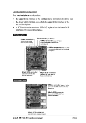
Two-backplane configuration In a two-backplane configuration: • the upper SCSI interface of the first backplane connects to the SCSI card • the lower SCSI interface connects to the upper SCSI interface of the second backplane • a SCSI multi-mode terminator ...card) 68-pin SCSI connector (connects the SCSI cable to the second backplane) Second backplane SMBus connector (upper 6-1 pins) (connects the SMB cable from the first backplane) 68-pin SCSI connector (connects the SCSI cable from the first backplane) 68-pin SCSI connector (with SCSI multi-mode terminator) ASUS AP1720-E1...
Two-backplane configuration In a two-backplane configuration: • the upper SCSI interface of the first backplane connects to the SCSI card • the lower SCSI interface connects to the upper SCSI interface of the second backplane • a SCSI multi-mode terminator ...card) 68-pin SCSI connector (connects the SCSI cable to the second backplane) Second backplane SMBus connector (upper 6-1 pins) (connects the SMB cable from the first backplane) 68-pin SCSI connector (connects the SCSI cable from the first backplane) 68-pin SCSI connector (with SCSI multi-mode terminator) ASUS AP1720-E1...
User Guide
Page 51
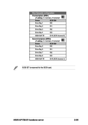
Non-Cascade configuration First backplane (BPB1) J1 setting (1-3 shorted, 2-4 shorted) Device SCSI ID# Drive Bay 1 ID0 Drive Bay 2 ID1 Drive Bay 3 ID2 Drive Bay 4 ID3 GEM SAF-TE ID15 (SCSI channel-0) Second backplane (BPB2) J1 setting (1-3 shorted, 2-4 shorted) Device SCSI ID# Drive Bay 5 ID0 Drive Bay 6 ID1 Drive Bay 7 ID2 Drive Bay 8 ID3 GEM SAF-TE ID15 (SCSI channel-1) SCSI ID7 is reserved for the SCSI card. ASUS AP1720-E1 barebone server 2-35
Non-Cascade configuration First backplane (BPB1) J1 setting (1-3 shorted, 2-4 shorted) Device SCSI ID# Drive Bay 1 ID0 Drive Bay 2 ID1 Drive Bay 3 ID2 Drive Bay 4 ID3 GEM SAF-TE ID15 (SCSI channel-0) Second backplane (BPB2) J1 setting (1-3 shorted, 2-4 shorted) Device SCSI ID# Drive Bay 5 ID0 Drive Bay 6 ID1 Drive Bay 7 ID2 Drive Bay 8 ID3 GEM SAF-TE ID15 (SCSI channel-1) SCSI ID7 is reserved for the SCSI card. ASUS AP1720-E1 barebone server 2-35

