User Guide
Page 3
... side cover 2-3 2.2 Motherboard information 2-4 2.3 Central Processing Unit (CPU 2-5 2.3.1 Installing a CPU 2-6 2.3.2 Installing the CPU heatsink and fan 2-7 2.4 System memory 2-10 2.4.1 Memory configurations 2-10 2.4.2 Installing a DIMM 2-11 2.4.3 Removing a DIMM 2-11 2.5 Front panel assembly 2-12 2.5.1 Removing the front panel assembly 2-12 2.5.2 Re-installing the front panel assembly 2-14 2.6 5.25-inch drives 2-15 2.7 Hard disk drives...
... side cover 2-3 2.2 Motherboard information 2-4 2.3 Central Processing Unit (CPU 2-5 2.3.1 Installing a CPU 2-6 2.3.2 Installing the CPU heatsink and fan 2-7 2.4 System memory 2-10 2.4.1 Memory configurations 2-10 2.4.2 Installing a DIMM 2-11 2.4.3 Removing a DIMM 2-11 2.5 Front panel assembly 2-12 2.5.1 Removing the front panel assembly 2-12 2.5.2 Re-installing the front panel assembly 2-14 2.6 5.25-inch drives 2-15 2.7 Hard disk drives...
User Guide
Page 27
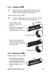
... DIMM matches the break on the socket. 2.4.2 Installing a DIMM Make sure to install a DIMM. Follow these steps to release the DIMM from the socket. ASUS AP1720-E1 barebone server 2-11 DDR DIMM notch Unlocked Retaining Clip 3. Failure to do so may cause damage to section "2.10 Removable components" for instructions. 1. To access the DIMM...
... DIMM matches the break on the socket. 2.4.2 Installing a DIMM Make sure to install a DIMM. Follow these steps to release the DIMM from the socket. ASUS AP1720-E1 barebone server 2-11 DDR DIMM notch Unlocked Retaining Clip 3. Failure to do so may cause damage to section "2.10 Removable components" for instructions. 1. To access the DIMM...
User Guide
Page 45
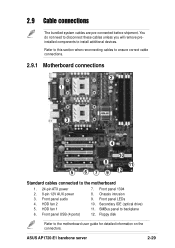
.... Floppy disk Refer to install additional devices. ASUS AP1720-E1 barebone server 2-29 Front panel LEDs 10. HDD fan 2 5. Front panel USB (4 ports) 7. Front panel audio 4. HDD fan 1 6. Front panel 1394 8. Refer to this section when reconnecting cables to ensure correct cable connections. 2.9.1 Motherboard connections 2 1 3 4 10 8 11 5 6 7 9 12 Standard cables connected to backplane 12...
.... Floppy disk Refer to install additional devices. ASUS AP1720-E1 barebone server 2-29 Front panel LEDs 10. HDD fan 2 5. Front panel USB (4 ports) 7. Front panel audio 4. HDD fan 1 6. Front panel 1394 8. Refer to this section when reconnecting cables to ensure correct cable connections. 2.9.1 Motherboard connections 2 1 3 4 10 8 11 5 6 7 9 12 Standard cables connected to backplane 12...
User Guide
Page 77
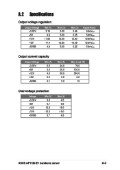
A.2 Specifications Output voltage regulation Output Voltage +3.33V +5V +12V -12V +5VSB Min (V) 3.16 4.8 11.52 -11.4 4.8 Nom (V) 3.30 5.00 12.00 -12.20 5.00 Max (V) 3.46 5.25 12.60 -13.08 5.25 Ripple/Noise 50mVp-p 50mVp-p 120mVp-p 120mVp-p 50mVp-p Output current capacity Output Voltage +3.33V +5V +12V -12V +5VSB Min (A) 0.5 2.0 4.0 0.0 0.1 Max (A) 24.0 20.0 30.0 0.5 2.0 Max. Load (W) 79.0 100.0 360.0 6.0 10 Over-voltage protection Voltage +3.33V +5V +12V +12V +5VSB Min (V) 3.9 5.7 13.3 -13.3 5.7 Max (V) 4.5 6.5 15.0 -15.0 6.5 ASUS AP1720-E1 barebone server A-3
A.2 Specifications Output voltage regulation Output Voltage +3.33V +5V +12V -12V +5VSB Min (V) 3.16 4.8 11.52 -11.4 4.8 Nom (V) 3.30 5.00 12.00 -12.20 5.00 Max (V) 3.46 5.25 12.60 -13.08 5.25 Ripple/Noise 50mVp-p 50mVp-p 120mVp-p 120mVp-p 50mVp-p Output current capacity Output Voltage +3.33V +5V +12V -12V +5VSB Min (A) 0.5 2.0 4.0 0.0 0.1 Max (A) 24.0 20.0 30.0 0.5 2.0 Max. Load (W) 79.0 100.0 360.0 6.0 10 Over-voltage protection Voltage +3.33V +5V +12V +12V +5VSB Min (V) 3.9 5.7 13.3 -13.3 5.7 Max (V) 4.5 6.5 15.0 -15.0 6.5 ASUS AP1720-E1 barebone server A-3