User Guide
Page 9
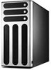
ASUS AP1720-E1 user guide 1-1 Product introduction Chapter 1 This chapter describes the general features of the barebone server. It includes sections on front panel and rear panel specifications.
ASUS AP1720-E1 user guide 1-1 Product introduction Chapter 1 This chapter describes the general features of the barebone server. It includes sections on front panel and rear panel specifications.
User Guide
Page 10
... rackmount chassis with the items on the following table. Contact your ASUS AP1720-E1 package with : • ASUS PC-DL Deluxe motherboard • 450W power supply • SCSI backplane board (2 pieces) (1 piece) • ASUS U160/320 SCSI card/SCSI cable • 52x CD-ROM drive...System keys ( 2 pcs.) 5) Bundled CDs • AP1720-E1 support CD • ASWM software CD • TrendMicro® ServerProtect® CD 6) Documentation • ASUS AP1720-E1 user guide • ASUS PC-DL Deluxe user guide 7) Optional items • ASUS AK25 rackmount rail kit • AK25 internal HDD cage (...
... rackmount chassis with the items on the following table. Contact your ASUS AP1720-E1 package with : • ASUS PC-DL Deluxe motherboard • 450W power supply • SCSI backplane board (2 pieces) (1 piece) • ASUS U160/320 SCSI card/SCSI cable • 52x CD-ROM drive...System keys ( 2 pcs.) 5) Bundled CDs • AP1720-E1 support CD • ASWM software CD • TrendMicro® ServerProtect® CD 6) Documentation • ASUS AP1720-E1 user guide • ASUS PC-DL Deluxe user guide 7) Optional items • ASUS AK25 rackmount rail kit • AK25 internal HDD cage (...
User Guide
Page 11
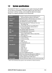
... Deluxe (ATX form factor: 12 in x 9.6 in 604-pin sockets, and includes the latest technologies through the chipsets embedded on internal connectors. ASUS AP1720-E1 barebone server 1-3 Chassis Motherboard Chipset Processor Memory LAN IEEE 1394 RAID Expansion slots Drive bays Front I/O Rear panel I /O Controller Hub (ICH5R) Supports dual Intel® ...
... Deluxe (ATX form factor: 12 in x 9.6 in 604-pin sockets, and includes the latest technologies through the chipsets embedded on internal connectors. ASUS AP1720-E1 barebone server 1-3 Chassis Motherboard Chipset Processor Memory LAN IEEE 1394 RAID Expansion slots Drive bays Front I/O Rear panel I /O Controller Hub (ICH5R) Supports dual Intel® ...
User Guide
Page 13
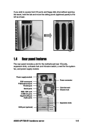
... port Serial ports IEEE 1394 port 4 USB 2.0 ports Gigabit LAN port Audio ports SCSI port (optional) Power connector 12cm fan vent Chassis lock Expansion slots ASUS AP1720-E1 barebone server 1-5 If you wish to access front I/O ports and floppy disk drive without opening the bezel, hold the tab and move the sliding panel...
... port Serial ports IEEE 1394 port 4 USB 2.0 ports Gigabit LAN port Audio ports SCSI port (optional) Power connector 12cm fan vent Chassis lock Expansion slots ASUS AP1720-E1 barebone server 1-5 If you wish to access front I/O ports and floppy disk drive without opening the bezel, hold the tab and move the sliding panel...
User Guide
Page 17
Hardware setup ASUS AP1720-E1 barebone server 2-1 Chapter 2 This chapter lists the hardware setup procedures that you have to perform when installing or removing system components.
Hardware setup ASUS AP1720-E1 barebone server 2-1 Chapter 2 This chapter lists the hardware setup procedures that you have to perform when installing or removing system components.
User Guide
Page 19
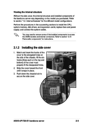
... fit the designated holes. 2. Push down the chassis lock to section "1.5 Internal features" for instructions. 2.1.2 Installing the side cover 1. Refer to secure the side cover. 1 2 3 ASUS AP1720-E1 barebone server 2-3 Slide the cover toward the front until it snaps in the succeeding sections to access the DIMM sockets and internal connectors. You may...
... fit the designated holes. 2. Push down the chassis lock to section "1.5 Internal features" for instructions. 2.1.2 Installing the side cover 1. Refer to secure the side cover. 1 2 3 ASUS AP1720-E1 barebone server 2-3 Slide the cover toward the front until it snaps in the succeeding sections to access the DIMM sockets and internal connectors. You may...
User Guide
Page 21
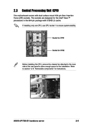
If installing only one CPU, use CPU socket 1 to section "2.10 Removable components" for instructions. ASUS AP1720-E1 barebone server 2-5 The sockets are designed for the installation. 2.3 Central Processing Unit (CPU) The motherboard comes with 512KB L2 cache. Refer to ensure system stability. Socket for CPU1 Socket for CPU2 Before installing the CPU, remove the chassis fan attached to the inner side of the rear panel to allow enough space for the Intel® Xeon™ processors in the 604-pin package with dual surface mount 604-pin Zero Insertion Force (ZIF) sockets.
If installing only one CPU, use CPU socket 1 to section "2.10 Removable components" for instructions. ASUS AP1720-E1 barebone server 2-5 The sockets are designed for the installation. 2.3 Central Processing Unit (CPU) The motherboard comes with 512KB L2 cache. Refer to ensure system stability. Socket for CPU1 Socket for CPU2 Before installing the CPU, remove the chassis fan attached to the inner side of the rear panel to allow enough space for the Intel® Xeon™ processors in the 604-pin package with dual surface mount 604-pin Zero Insertion Force (ZIF) sockets.
User Guide
Page 23
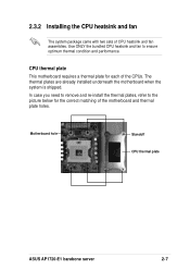
... case you need to remove and re-install the thermal plates, refer to ensure optimum thermal condition and performance. Motherboard hole Standoff CPU thermal plate ASUS AP1720-E1 barebone server 2-7 The thermal plates are already installed underneath the motherboard when the system is shipped. 2.3.2 Installing the CPU heatsink and fan The system package...
... case you need to remove and re-install the thermal plates, refer to ensure optimum thermal condition and performance. Motherboard hole Standoff CPU thermal plate ASUS AP1720-E1 barebone server 2-7 The thermal plates are already installed underneath the motherboard when the system is shipped. 2.3.2 Installing the CPU heatsink and fan The system package...
User Guide
Page 25
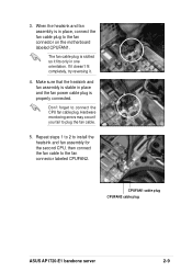
... the heatsink and fan assembly is stable in place and the fan power cable plug is in one orientation. CPUFAN1 cable plug CPUFAN2 cable plug ASUS AP1720-E1 barebone server 2-9 If it doesn't fit completely, try reversing it fits only in place, connect the fan cable plug to plug the fan cable. 5. Hardware...
... the heatsink and fan assembly is stable in place and the fan power cable plug is in one orientation. CPUFAN1 cable plug CPUFAN2 cable plug ASUS AP1720-E1 barebone server 2-9 If it doesn't fit completely, try reversing it fits only in place, connect the fan cable plug to plug the fan cable. 5. Hardware...
User Guide
Page 27
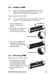
... DIMM from the socket. 2. Firmly insert the DIMM into the socket until the retaining clips snap back in place and the DIMM is properly seated. ASUS AP1720-E1 barebone server 2-11 To access the DIMM sockets, remove the upper HDD fan cage. Refer to release the DIMM from the socket. DDR DIMM notch...
... DIMM from the socket. 2. Firmly insert the DIMM into the socket until the retaining clips snap back in place and the DIMM is properly seated. ASUS AP1720-E1 barebone server 2-11 To access the DIMM sockets, remove the upper HDD fan cage. Refer to release the DIMM from the socket. DDR DIMM notch...
User Guide
Page 29
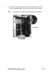
3. Hinge-like tabs from the holes on the right side of the front panel to completely detach the front panel assembly from the chassis. Unhook the hinge-like tab ASUS AP1720-E1 barebone server 2-13 Do not use too much force when removing the front panel assembly.
3. Hinge-like tabs from the holes on the right side of the front panel to completely detach the front panel assembly from the chassis. Unhook the hinge-like tab ASUS AP1720-E1 barebone server 2-13 Do not use too much force when removing the front panel assembly.
User Guide
Page 31
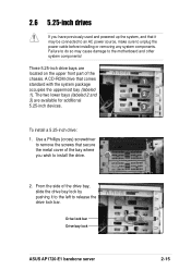
... you have previously used and powered up the system, and that it to the left to install the drive. 2. Drive lock bar Drive bay lock ASUS AP1720-E1 barebone server 2-15 2.6 5.25-inch drives If you wish to release the drive lock bar. Failure to do so may be connected to an AC...
... you have previously used and powered up the system, and that it to the left to install the drive. 2. Drive lock bar Drive bay lock ASUS AP1720-E1 barebone server 2-15 2.6 5.25-inch drives If you wish to release the drive lock bar. Failure to do so may be connected to an AC...
User Guide
Page 33
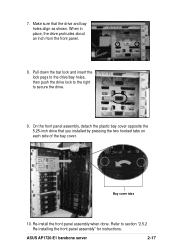
... lock pegs to the drive/bay holes, then push the drive lock to the right to section "2.5.2 Re-installing the front panel assembly" for instructions. ASUS AP1720-E1 barebone server 2-17 On the front panel assembly, detach the plastic bay cover opposite the 5.25-inch drive that the drive and bay holes align...
... lock pegs to the drive/bay holes, then push the drive lock to the right to section "2.5.2 Re-installing the front panel assembly" for instructions. ASUS AP1720-E1 barebone server 2-17 On the front panel assembly, detach the plastic bay cover opposite the 5.25-inch drive that the drive and bay holes align...
User Guide
Page 35
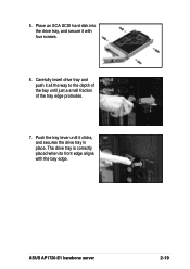
5. The drive tray is correctly placed when its front edge aligns with four screws. 6. Place an SCA SCSI hard disk into the drive tray, and secure it clicks, and secures the drive tray in place. ASUS AP1720-E1 barebone server 2-19 Push the tray lever until just a small fraction of the tray edge protrudes. 7. Carefully insert drive tray and push it all the way to the depth of the bay until it with the bay edge.
5. The drive tray is correctly placed when its front edge aligns with four screws. 6. Place an SCA SCSI hard disk into the drive tray, and secure it clicks, and secures the drive tray in place. ASUS AP1720-E1 barebone server 2-19 Push the tray lever until just a small fraction of the tray edge protrudes. 7. Carefully insert drive tray and push it all the way to the depth of the bay until it with the bay edge.
User Guide
Page 37
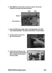
Check the HDD jumper setting. 3. Hole 3 Hole 1 Rail end Drive connectors 4. Refer to the depth of the bay until the rail locks clicks, indicating that the drive is recommended. 5. ASUS AP1720-E1 barebone server 2-21 Attach Rail 2 to the other side of the drive connectors. Carefully insert the drive into a bay on the HDD for the setting description. The rail end should be on the side of the drive as shown. The setting "Cable Select" is securely in place. Push the drive all the way to the label pasted on the front panel. 6.
Check the HDD jumper setting. 3. Hole 3 Hole 1 Rail end Drive connectors 4. Refer to the depth of the bay until the rail locks clicks, indicating that the drive is recommended. 5. ASUS AP1720-E1 barebone server 2-21 Attach Rail 2 to the other side of the drive connectors. Carefully insert the drive into a bay on the HDD for the setting description. The rail end should be on the side of the drive as shown. The setting "Cable Select" is securely in place. Push the drive all the way to the label pasted on the front panel. 6.
User Guide
Page 39
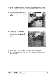
Re-install the side cover when done. Check the HDD jumper setting. 4. Carefully insert the drive into a bay on the back of the drive. 7. ASUS AP1720-E1 barebone server 2-23 Follow steps 2 to 5 if you wish to the label pasted on the HDD for the setting description. Refer to install other hard disk drives. 8. The setting "Cable Select" is recommended. 5. Connect the IDE and power cables to section "21.2 Installing the side cover." Refer to their corresponding connectors on the second drive cage as shown. 6.
Re-install the side cover when done. Check the HDD jumper setting. 4. Carefully insert the drive into a bay on the back of the drive. 7. ASUS AP1720-E1 barebone server 2-23 Follow steps 2 to 5 if you wish to the label pasted on the HDD for the setting description. Refer to install other hard disk drives. 8. The setting "Cable Select" is recommended. 5. Connect the IDE and power cables to section "21.2 Installing the side cover." Refer to their corresponding connectors on the second drive cage as shown. 6.
User Guide
Page 41
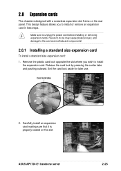
... plastic card lock opposite the slot where you to the card and motheboard components! 2.8.1 Installing a standard size expansion card To install a standard size expansion card: 1. ASUS AP1720-E1 barebone server 2-25 Carefully install an expansion card making sure that it is designed with a screwless expansion slot frame on the slot. This design feature...
... plastic card lock opposite the slot where you to the card and motheboard components! 2.8.1 Installing a standard size expansion card To install a standard size expansion card: 1. ASUS AP1720-E1 barebone server 2-25 Carefully install an expansion card making sure that it is designed with a screwless expansion slot frame on the slot. This design feature...
User Guide
Page 43
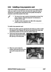
... the rear panel. 3. Set the card lock aside for instructions on installing the drive cage. 2. The internal drive cage is level with the PCI slot. ASUS AP1720-E1 barebone server 2-27 Remove the plastic card lock opposite the slot where you wish to install the expansion card. Tilt the long card as some...
... the rear panel. 3. Set the card lock aside for instructions on installing the drive cage. 2. The internal drive cage is level with the PCI slot. ASUS AP1720-E1 barebone server 2-27 Remove the plastic card lock opposite the slot where you wish to install the expansion card. Tilt the long card as some...
User Guide
Page 45
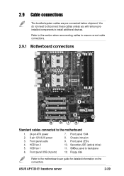
... additional devices. Floppy disk Refer to the motherboard 1. 24-pin ATX power 2. 8-pin 12V AUX power 3. Front panel LEDs 10. Secondary IDE (optical drive) 11. ASUS AP1720-E1 barebone server 2-29 Front panel audio 4. Refer to this section when reconnecting cables to ensure correct cable connections. 2.9.1 Motherboard connections 2 1 3 4 10 8 11 5 6 7 9 12 Standard cables...
... additional devices. Floppy disk Refer to the motherboard 1. 24-pin ATX power 2. 8-pin 12V AUX power 3. Front panel LEDs 10. Secondary IDE (optical drive) 11. ASUS AP1720-E1 barebone server 2-29 Front panel audio 4. Refer to this section when reconnecting cables to ensure correct cable connections. 2.9.1 Motherboard connections 2 1 3 4 10 8 11 5 6 7 9 12 Standard cables...
User Guide
Page 47
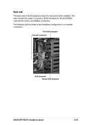
Back side The back side of SCSI backplane faces the rear panel when installed. This side includes the power connectors, SCSI interfaces for the SCSI/RAID card and terminator, and SMBus connectors. The following picture shows a two-backplane configuration in a cascade connection. First SCSI backplane Cascade connection SCSI terminator Second SCSI backplane ASUS AP1720-E1 barebone server 2-31
Back side The back side of SCSI backplane faces the rear panel when installed. This side includes the power connectors, SCSI interfaces for the SCSI/RAID card and terminator, and SMBus connectors. The following picture shows a two-backplane configuration in a cascade connection. First SCSI backplane Cascade connection SCSI terminator Second SCSI backplane ASUS AP1720-E1 barebone server 2-31


