
AP1710-E1 English version manual
Page 3
... the side cover 2-2 2.1.2 Reinstalling the side cover 2-3 2.2 Motherboard information 2-4 2.3 Central Processing Unit (CPU 2-5 2.3.1 Overview 2-5 2.3.2 Installing the CPU 2-5 2.3.3 Installing the CPU heatsink and fan 2-7 2.4 System memory 2-9 2.4.1 Overview 2-9 2.4.2 Memory configurations 2-9 2.4.3 Installing a DIMM 2-11 2.4.4 Removing a DIMM 2-11 2.5 Front panel assembly 2-12 2.5.1 Removing the front panel assembly 2-12 2.5.2 Reinstalling the front panel assembly 2-14 2.6 5.25-inch...
... the side cover 2-2 2.1.2 Reinstalling the side cover 2-3 2.2 Motherboard information 2-4 2.3 Central Processing Unit (CPU 2-5 2.3.1 Overview 2-5 2.3.2 Installing the CPU 2-5 2.3.3 Installing the CPU heatsink and fan 2-7 2.4 System memory 2-9 2.4.1 Overview 2-9 2.4.2 Memory configurations 2-9 2.4.3 Installing a DIMM 2-11 2.4.4 Removing a DIMM 2-11 2.5 Front panel assembly 2-12 2.5.1 Removing the front panel assembly 2-12 2.5.2 Reinstalling the front panel assembly 2-14 2.6 5.25-inch...

AP1710-E1 English version manual
Page 13
...memory Ready for 4 GB DDR DIMMs for AA4 models only) supports: - 4 x SATAII 300 with removable front door bezel and chassis foot stand or roller-wheels. Motherboard Chipset ASUS NCLV-D (A) (E-ATX form factor: 12 in x 10.5 in 604-pin sockets, and includes the latest technologies through the chipsets embedded on the next page) ASUS AP1710-E1... 1-3 Chassis Pedestal or rackmount 5U with RAID 0, RAID 1, and RAID 0+1 configuration - Zero-Channel RAID (optional) (continued on the motherboard. 1.2 System specifications The ASUS AP1710-E1 is a barebone ...
...memory Ready for 4 GB DDR DIMMs for AA4 models only) supports: - 4 x SATAII 300 with removable front door bezel and chassis foot stand or roller-wheels. Motherboard Chipset ASUS NCLV-D (A) (E-ATX form factor: 12 in x 10.5 in 604-pin sockets, and includes the latest technologies through the chipsets embedded on the next page) ASUS AP1710-E1... 1-3 Chassis Pedestal or rackmount 5U with RAID 0, RAID 1, and RAID 0+1 configuration - Zero-Channel RAID (optional) (continued on the motherboard. 1.2 System specifications The ASUS AP1710-E1 is a barebone ...

AP1710-E1 English version manual
Page 14
... 2 x USB ports 1 x Serial port 1 x Parallel port 1 x PS/2 keyboard port 1 x PS/2 mouse port 2 x LAN (RJ-45) ports 2 x USB ports 1 x VGA port ASUS Server Web-based Management (ASWM) 2.0 Voltage, temperature, CPU and memory utilization, and fan speed monitoring Automatic Server Restart (ASR) feature 600 W single/dual/redundant power supply (with 24-pin and 8-pin...
... 2 x USB ports 1 x Serial port 1 x Parallel port 1 x PS/2 keyboard port 1 x PS/2 mouse port 2 x LAN (RJ-45) ports 2 x USB ports 1 x VGA port ASUS Server Web-based Management (ASWM) 2.0 Voltage, temperature, CPU and memory utilization, and fan speed monitoring Automatic Server Restart (ASR) feature 600 W single/dual/redundant power supply (with 24-pin and 8-pin...
AP1710-E1 English version manual
Page 27
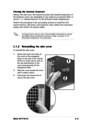
Refer to secure the side cover. 1 2 3 ASUS AP1710-E1 2-3 replace fans and power supply; You may need to remove some of the cover must properly fit the designated holes. 2. All the six hooks (three ... elongated holes on the side of the barebone server vary depending on the top and bottom) of the installed components to install the CPU, system memory, disk drives, and expansion cards; Perform the procedures in place. 3. Slide the cover toward the front until it snaps in the succeeding sections to access...
Refer to secure the side cover. 1 2 3 ASUS AP1710-E1 2-3 replace fans and power supply; You may need to remove some of the cover must properly fit the designated holes. 2. All the six hooks (three ... elongated holes on the side of the barebone server vary depending on the top and bottom) of the installed components to install the CPU, system memory, disk drives, and expansion cards; Perform the procedures in place. 3. Slide the cover toward the front until it snaps in the succeeding sections to access...
AP1710-E1 English version manual
Page 29
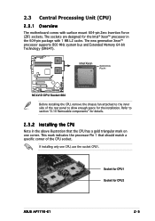
... in the above illustration that should match a specific corner of the rear panel to allow enough space for CPU2 ASUS AP1710-E1 2-5 The new generation Xeon™ processor supports 800 MHz system bus and Extended Memory 64-bit Technology (EM64T). Refer to the inner side of the CPU socket. 2.3 Central Processing Unit (CPU) 2.3.1 Overview...
... in the above illustration that should match a specific corner of the rear panel to allow enough space for CPU2 ASUS AP1710-E1 2-5 The new generation Xeon™ processor supports 800 MHz system bus and Extended Memory 64-bit Technology (EM64T). Refer to the inner side of the CPU socket. 2.3 Central Processing Unit (CPU) 2.3.1 Overview...
AP1710-E1 English version manual
Page 33
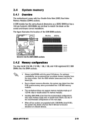
... optimum compatibility, we recommend that you installed four 2 GB DDR memory modules. • This motherboard does not support memory modules made up of the recommended configurations on the socket and ensure correct installation. ASUS AP1710-E1 2-9 Use any of 128 Mb chips or double-sided x16 memory modules. • Installing DDR DIMMs other than the recommended...
... optimum compatibility, we recommend that you installed four 2 GB DDR memory modules. • This motherboard does not support memory modules made up of the recommended configurations on the socket and ensure correct installation. ASUS AP1710-E1 2-9 Use any of 128 Mb chips or double-sided x16 memory modules. • Installing DDR DIMMs other than the recommended...

AP1710-E1 English version manual
Page 34
... size) DIMM pair in DDR_B2 and DDR_A2 (blue sockets) only. Populated - Obtain DDR DIMMs only from ASUS qualified vendors for the latest QVL. 2-10 Chapter 2: Hardware setup Visit the ASUS website (www.asus.com) for better system performance. Recommended memory configurations Mode DDR_B2 (blue) Sockets DDR_A2 DDR_B1 (blue) (black) Single-channel (1) Populated - - (2) - DDR_A1 (black...
... size) DIMM pair in DDR_B2 and DDR_A2 (blue sockets) only. Populated - Obtain DDR DIMMs only from ASUS qualified vendors for the latest QVL. 2-10 Chapter 2: Hardware setup Visit the ASUS website (www.asus.com) for better system performance. Recommended memory configurations Mode DDR_B2 (blue) Sockets DDR_A2 DDR_B1 (blue) (black) Single-channel (1) Populated - - (2) - DDR_A1 (black...

AP1710-E1 English version manual
Page 98
... need to clear the RTC when the system hangs due to pins 1-2. 4. Hold down and reboot the system so the BIOS can clear the CMOS memory of date, time, and system setup parameters by erasing the CMOS RTC RAM data. Removing the cap will cause system boot failure! Remove the onboard...
... need to clear the RTC when the system hangs due to pins 1-2. 4. Hold down and reboot the system so the BIOS can clear the CMOS memory of date, time, and system setup parameters by erasing the CMOS RTC RAM data. Removing the cap will cause system boot failure! Remove the onboard...

AP1710-E1 English version manual
Page 126
... field is enclosed in brackets, and is a brief description of a menu screen when there are items that menu. Configure DRAM Timing by SPD Memory Acceleration Mode DRAM Idle Timer DRAm Refresh Rate [Enabled] [Auto] [Auto] [Auto] Graphic Adapter Priority Graphics Aperture Size Spread Spectrum [AGP/PCI...Boot, and Exit) on the screen. 5.2.9 General help Advanced Chipset settings WARNING: Setting wrong values in ] [English] :[ST320413A] :[ASUS CD-S340] :[Not Detected] :[Not Detected] :[Not Detected] :[Not Detected] Main menu items Use [ENTER], [TAB] or [SHIFT-TAB] to malfunction....
... field is enclosed in brackets, and is a brief description of a menu screen when there are items that menu. Configure DRAM Timing by SPD Memory Acceleration Mode DRAM Idle Timer DRAm Refresh Rate [Enabled] [Auto] [Auto] [Auto] Graphic Adapter Priority Graphics Aperture Size Spread Spectrum [AGP/PCI...Boot, and Exit) on the screen. 5.2.9 General help Advanced Chipset settings WARNING: Setting wrong values in ] [English] :[ST320413A] :[ASUS CD-S340] :[Not Detected] :[Not Detected] :[Not Detected] :[Not Detected] Main menu items Use [ENTER], [TAB] or [SHIFT-TAB] to malfunction....

AP1710-E1 English version manual
Page 130
... Date : 07/07/04 Processor Type Speed Count : Intel(R) Xeon (TM) CPU 2.80GHz : 2800 MHz : 2 System Memory Size : 512MB AMI BIOS Displays the auto-detected BIOS information Processor Displays the auto-detected CPU specification System... Memory Displays the auto-detected system memory 5-16 Chapter 5: Motherboard information A T A + S - A T A P o r t s O n l y options are for detecting ATA/ATAPI devices. The BIOS automatically detects the items in ...
... Date : 07/07/04 Processor Type Speed Count : Intel(R) Xeon (TM) CPU 2.80GHz : 2800 MHz : 2 System Memory Size : 512MB AMI BIOS Displays the auto-detected BIOS information Processor Displays the auto-detected CPU specification System... Memory Displays the auto-detected system memory 5-16 Chapter 5: Motherboard information A T A + S - A T A P o r t s O n l y options are for detecting ATA/ATAPI devices. The BIOS automatically detects the items in ...
AP1710-E1 English version manual
Page 135
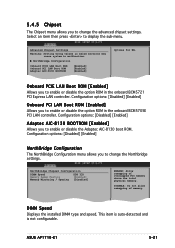
...[Enabled] Allows you to change the Northbridge settings. NorthBridge Chipset Configuration DIMM Speed Memory Remap Feature Memory Mirroring / Sparing DDR 333 [Enabled] [Disabled] ENABLE: Allow remapping of memory. DIMM Speed Displays the installed DIMM type and speed. NorthBridge Configuration Onboard PCIE ...8130 BOOTROM [Enabled] [Enabled] [Enabled] Options for NB. DISABLE: Do not allow remapping of overlapped PCI memory above the total physical memory. ASUS AP1710-E1 5-21 5.4.5 Chipset The Chipset menu allows you to enable or disable the option ROM in the onboard BCM5721...
...[Enabled] Allows you to change the Northbridge settings. NorthBridge Chipset Configuration DIMM Speed Memory Remap Feature Memory Mirroring / Sparing DDR 333 [Enabled] [Disabled] ENABLE: Allow remapping of memory. DIMM Speed Displays the installed DIMM type and speed. NorthBridge Configuration Onboard PCIE ...8130 BOOTROM [Enabled] [Enabled] [Enabled] Options for NB. DISABLE: Do not allow remapping of overlapped PCI memory above the total physical memory. ASUS AP1710-E1 5-21 5.4.5 Chipset The Chipset menu allows you to enable or disable the option ROM in the onboard BCM5721...

AP1710-E1 English version manual
Page 136
... Parallel Port Address Parallel Port Mode Parallel Port IRQ [3F8/IRQ4] [2F8/IRQ3] [378] [Normal] [IRQ7] Allows BIOS to remap the overlap PCI memory over the total physical memory. Configuration options: [1.9] [1.7] Parallel Port IRQ [IRQ7] Sets the Parallel port IRQ. Configuration options: [Normal] [Bi-directional] [EPP] [ECP] E ... Port2 base address. Configuration options: [Disabled] [Enabled] Memory Mirroring/Sparing [Disabled] Allows you to enable memory mirroring or sparing under certain memory configurations. Memory Remap Feature [Enabled] Allows you to Select Serial Port1 Base ...
... Parallel Port Address Parallel Port Mode Parallel Port IRQ [3F8/IRQ4] [2F8/IRQ3] [378] [Normal] [IRQ7] Allows BIOS to remap the overlap PCI memory over the total physical memory. Configuration options: [1.9] [1.7] Parallel Port IRQ [IRQ7] Sets the Parallel port IRQ. Configuration options: [Normal] [Bi-directional] [EPP] [ECP] E ... Port2 base address. Configuration options: [Disabled] [Enabled] Memory Mirroring/Sparing [Disabled] Allows you to enable memory mirroring or sparing under certain memory configurations. Memory Remap Feature [Enabled] Allows you to Select Serial Port1 Base ...
AP1710-E1 English version manual
Page 137
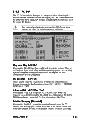
... requests for PCI/PnP devices. The menu includes setting IRQ and DMA channel resources for either PCI/PnP or legacy ISA devices, and setting the memory size block for boot if your system has a Plug and Play operating system. Change Option F1 General Help F10 Save and Exit ESC Exit Plug... PnP menu items allow you to select the value in below sections may cause system to malfunction. Select Screen Select Item +- Configuration options: [Disabled] [Enabled] ASUS AP1710-E1 5-23
... requests for PCI/PnP devices. The menu includes setting IRQ and DMA channel resources for either PCI/PnP or legacy ISA devices, and setting the memory size block for boot if your system has a Plug and Play operating system. Change Option F1 General Help F10 Save and Exit ESC Exit Plug... PnP menu items allow you to select the value in below sections may cause system to malfunction. Select Screen Select Item +- Configuration options: [Disabled] [Enabled] ASUS AP1710-E1 5-23

AP1710-E1 English version manual
Page 138
...menu. IRQ-15 assigned to scroll down key to DMA Channel 0 DMA Channel 1 DMA Channel 3 DMA Channel 5 DMA Channel 6 DMA Channel 7 Reserved Memory Size [PCI Device] [PCI Device] [PCI Device] [PCI Device] [PCI Device] [PCI Device] [PCI Device] [Disabled] Select Screen Select Item ...+- Configuration options: [PCI Device] [Reserved] Reserved Memory Size [Disabled] Allows you to assign a PCI slot to a PCI IDE card, when required. When set the reserved memory size. Configuration options: [Auto] [PCI Slot1] [PCI Slot2] [PCI Slot3] [PCI Slot4]...
...menu. IRQ-15 assigned to scroll down key to DMA Channel 0 DMA Channel 1 DMA Channel 3 DMA Channel 5 DMA Channel 6 DMA Channel 7 Reserved Memory Size [PCI Device] [PCI Device] [PCI Device] [PCI Device] [PCI Device] [PCI Device] [PCI Device] [Disabled] Select Screen Select Item ...+- Configuration options: [PCI Device] [Reserved] Reserved Memory Size [Disabled] Allows you to assign a PCI slot to a PCI IDE card, when required. When set the reserved memory size. Configuration options: [Auto] [PCI Slot1] [PCI Slot2] [PCI Slot3] [PCI Slot4]...

AP1710-E1 English version manual
Page 156
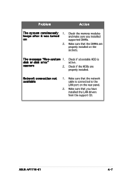
... the monitor do not light up 1. The keyboard does not work Check if the keyboard cable is turned on. The system does not 1. Check the memory modules perform power-on self and make sure that the system is properly connected to make sure you may encounter are not due to a grounded...
... the monitor do not light up 1. The keyboard does not work Check if the keyboard cable is turned on. The system does not 1. Check the memory modules perform power-on self and make sure that the system is properly connected to make sure you may encounter are not due to a grounded...
AP1710-E1 English version manual
Page 157
T h e m e s s a g e " N o n - Network connection not available 1. ASUS AP1710-E1 A-7 Problem Action T h e s y s t e m c o n t i n u o u s l y 1. Make sure that you installed on the sockets. Make sure that the network cable is active. Check if the HDDs are properly installed on supported DIMMs. 2. disk or disk error" appears 2. Make sure that the DIMMs are properly installed. s y s t e m 1. Check the memory modules beeps after it...
T h e m e s s a g e " N o n - Network connection not available 1. ASUS AP1710-E1 A-7 Problem Action T h e s y s t e m c o n t i n u o u s l y 1. Make sure that you installed on the sockets. Make sure that the network cable is active. Check if the HDDs are properly installed on supported DIMMs. 2. disk or disk error" appears 2. Make sure that the DIMMs are properly installed. s y s t e m 1. Check the memory modules beeps after it...