AP1710-E1 English version manual
Page 12
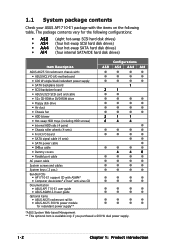
...; SATA backplane board • SCSI backplane board • ASUS U320 SCSI card and cable • 52x CD-ROM or DVD-ROM drive • Floppy disk drive • Air duct • Chassis fan • HDD blower • Hot-swap HDD trays (including HDD screws) • Internal HDD rails (4 pairs) • Chassis roller wheels (4 sets) • Front I/O board • SATA signal cable (4 sets) • SATA power cable • SMBus cable • Dummy covers • Parallel port cable AC power cable System screws and cables System keys ( 2 pcs.) Bundled CDs • AP1710-E1 support...
...; SATA backplane board • SCSI backplane board • ASUS U320 SCSI card and cable • 52x CD-ROM or DVD-ROM drive • Floppy disk drive • Air duct • Chassis fan • HDD blower • Hot-swap HDD trays (including HDD screws) • Internal HDD rails (4 pairs) • Chassis roller wheels (4 sets) • Front I/O board • SATA signal cable (4 sets) • SATA power cable • SMBus cable • Dummy covers • Parallel port cable AC power cable System screws and cables System keys ( 2 pcs.) Bundled CDs • AP1710-E1 support...

AP1710-E1 English version manual
Page 15
... covers the system components on the front panel. For future installation of 5.25-inch devices, two drive bays are located on the front panel and serves as security. The drive bays, power and reset buttons, LED indicators, CD-ROM drive, floppy drive, and USB 2.0 ports are available. (AS8) CD-ROM drive Empty 5.25-inch bays Power button Reset button Message LED HDD access LED Power LED Floppy disk drive USB 2.0 ports Security lock Drive bays ASUS AP1710-E1 1-5 Open the bezel to access the front panel components. 1.3 Front panel features The AP1710-E1 chassis displays...
... covers the system components on the front panel. For future installation of 5.25-inch devices, two drive bays are located on the front panel and serves as security. The drive bays, power and reset buttons, LED indicators, CD-ROM drive, floppy drive, and USB 2.0 ports are available. (AS8) CD-ROM drive Empty 5.25-inch bays Power button Reset button Message LED HDD access LED Power LED Floppy disk drive USB 2.0 ports Security lock Drive bays ASUS AP1710-E1 1-5 Open the bezel to access the front panel components. 1.3 Front panel features The AP1710-E1 chassis displays...
AP1710-E1 English version manual
Page 19
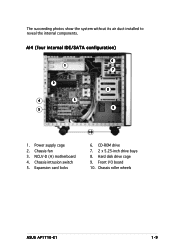
Chassis intrusion switch 5. Chassis roller wheels ASUS AP1710-E1 1-9 CD-ROM drive 7. 2 x 5.25-inch drive bays 8. Hard disk drive cage 9. Power supply cage 2. Expansion card locks 10 6. Front I/O board 10. AI4 (four internal IDE/SATA configuration) 6 1 7 2 4 3 5 8 9 1. NCLV-D (A) motherboard 4. Chassis fan 3. The succeeding photos show the system without its air duct installed to reveal the internal components.
Chassis intrusion switch 5. Chassis roller wheels ASUS AP1710-E1 1-9 CD-ROM drive 7. 2 x 5.25-inch drive bays 8. Hard disk drive cage 9. Power supply cage 2. Expansion card locks 10 6. Front I/O board 10. AI4 (four internal IDE/SATA configuration) 6 1 7 2 4 3 5 8 9 1. NCLV-D (A) motherboard 4. Chassis fan 3. The succeeding photos show the system without its air duct installed to reveal the internal components.

AP1710-E1 English version manual
Page 21
Chassis fan 3. Chassis intrusion switch 5. Front I/O board 10. SCSI backplane (hidden) 14. NCLV-D (A) motherboard 4. CD-ROM drive 7. 2 x 5.25-inch drive bays 8. Hard disk drive cage 9. SATA backplane (hidden) 13. ASUS AP1710-E1 1-11 Expansion card locks 6. AS8 (eight hot-swap SCSI configuration) 13 11 14 15 16 1. Second HDD blower* * The hard disk drive cage is behind the blower. HDD blower* 12. Power supply cage 2. Chassis roller wheels 11. Second SCSI backplane (hidden) 16. ASUS U320 SCSI card 15.
Chassis fan 3. Chassis intrusion switch 5. Front I/O board 10. SCSI backplane (hidden) 14. NCLV-D (A) motherboard 4. CD-ROM drive 7. 2 x 5.25-inch drive bays 8. Hard disk drive cage 9. SATA backplane (hidden) 13. ASUS AP1710-E1 1-11 Expansion card locks 6. AS8 (eight hot-swap SCSI configuration) 13 11 14 15 16 1. Second HDD blower* * The hard disk drive cage is behind the blower. HDD blower* 12. Power supply cage 2. Chassis roller wheels 11. Second SCSI backplane (hidden) 16. ASUS U320 SCSI card 15.
AP1710-E1 English version manual
Page 33
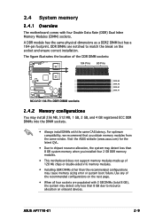
... motherboard does not support memory modules made up of 128 Mb chips or double-sided x16 memory modules. • Installing DDR DIMMs other than the recommended configurations may cause memory sizing error or system boot failure. The figure illustrates the location of the recommended configurations on the next page. • When all four sockets are notched to resource allocation on the socket and ensure correct installation. Use...
... motherboard does not support memory modules made up of 128 Mb chips or double-sided x16 memory modules. • Installing DDR DIMMs other than the recommended configurations may cause memory sizing error or system boot failure. The figure illustrates the location of the recommended configurations on the next page. • When all four sockets are notched to resource allocation on the socket and ensure correct installation. Use...

AP1710-E1 English version manual
Page 52
... USB cable 6. CPU fan2 2. 24-pin ATX power 10. Chassis intrusion 14. CPU fan1 Refer to backplane 7. Serial port (COM2) 5. Front panel cable 15. Rear fan1 3. Serial ATA RAID connectors 8. Primary IDE cable 11. Power supply SMBus 4. SMBus cable to the motherboard user guide for detailed information on the connectors. 2-28 Chapter 2: Hardware setup You do not need to disconnect these cables unless you will remove pre-installed components to install additional devices. • Refer to this section when reconnecting cables...
... USB cable 6. CPU fan2 2. 24-pin ATX power 10. Chassis intrusion 14. CPU fan1 Refer to backplane 7. Serial port (COM2) 5. Front panel cable 15. Rear fan1 3. Serial ATA RAID connectors 8. Primary IDE cable 11. Power supply SMBus 4. SMBus cable to the motherboard user guide for detailed information on the connectors. 2-28 Chapter 2: Hardware setup You do not need to disconnect these cables unless you will remove pre-installed components to install additional devices. • Refer to this section when reconnecting cables...

AP1710-E1 English version manual
Page 105
... covered hole on the IDE ribbon cable to the hard disk documentation for an Ultra DMA 100/66 IDE master device (hard disk drive). NCLV-D NCLV-D IDE connectors SEC_IDE1 PIN 1 PRI_IDE1 PIN 1 NOTE: Orient the red markings (usually zigzag) on the Ultra DMA cable connector. If you install two hard disk drives, you connect the IDE cable. • Use the 80-conductor IDE cable for Ultra DMA 100/66 signal cables. 2 . ASUS AP1710-E1...
... covered hole on the IDE ribbon cable to the hard disk documentation for an Ultra DMA 100/66 IDE master device (hard disk drive). NCLV-D NCLV-D IDE connectors SEC_IDE1 PIN 1 PRI_IDE1 PIN 1 NOTE: Orient the red markings (usually zigzag) on the Ultra DMA cable connector. If you install two hard disk drives, you connect the IDE cable. • Use the 80-conductor IDE cable for Ultra DMA 100/66 signal cables. 2 . ASUS AP1710-E1...

AP1710-E1 English version manual
Page 106
... create a Serial ATA RAID set the C o n f i g u r e S A T A A s item in S t a n d a r d I D E mode by default. These connectors are for the Serial ATA signal cables for details. 3 . Serial ATA connectors (7-pin SATA1, SATA2) These connectors are set to these connectors, set using the connectors in the BIOS to [RAID]. Serial ATA hard disk drive connection Connector SATA1 SATA2 Setting Master Slave Use Boot disk Data disk 4-12 Chapter 4: Motherboard information Refer to the SATA1 or SATA2 connector. See section "5.3.5 IDE Configuration" for Serial ATA hard disk drives.
... create a Serial ATA RAID set the C o n f i g u r e S A T A A s item in S t a n d a r d I D E mode by default. These connectors are for the Serial ATA signal cables for details. 3 . Serial ATA connectors (7-pin SATA1, SATA2) These connectors are set to these connectors, set using the connectors in the BIOS to [RAID]. Serial ATA hard disk drive connection Connector SATA1 SATA2 Setting Master Slave Use Boot disk Data disk 4-12 Chapter 4: Motherboard information Refer to the SATA1 or SATA2 connector. See section "5.3.5 IDE Configuration" for Serial ATA hard disk drives.

AP1710-E1 English version manual
Page 107
... drives that you cannot enter the RAID utility and SATA BIOS setup during POST. 5 . The read or write activities of any device connected to the primary/secondary IDE connectors or the SATA connectors cause this LED to light up to the hard disk activity LED. Serial ATA RAID connectors (7-pin SATA_RAID1, S A T A _ R A I D 2 , S A T A _ R A I D 3 , S A T A _ R A I D 4 ) (Optional) These connectors are for Serial ATA signal cables. NCLV-D HDLED1 1 SCSI_ACTLED+ SCSI_ACTLEDSCSI_ACTLEDSCSI_ACTLED+ NCLV-D SCSI/SATA card activity LED connector ASUS AP1710-E1 4-13 4 . These connectors support...
... drives that you cannot enter the RAID utility and SATA BIOS setup during POST. 5 . The read or write activities of any device connected to the primary/secondary IDE connectors or the SATA connectors cause this LED to light up to the hard disk activity LED. Serial ATA RAID connectors (7-pin SATA_RAID1, S A T A _ R A I D 2 , S A T A _ R A I D 3 , S A T A _ R A I D 4 ) (Optional) These connectors are for Serial ATA signal cables. NCLV-D HDLED1 1 SCSI_ACTLED+ SCSI_ACTLEDSCSI_ACTLEDSCSI_ACTLED+ NCLV-D SCSI/SATA card activity LED connector ASUS AP1710-E1 4-13 4 . These connectors support...

AP1710-E1 English version manual
Page 128
... The BIOS automatically detects the connected IDE devices. There is installed in the system. Select [CDROM] if you are not user-configurable. When set to [Disabled], the data transfer from and to display the IDE device information. Configuration options: [Not Installed] [Auto] [CDROM] [ARMD] LBA/Large Mode [Auto] Enables or disables the LBA mode. Select a device item, then press to the device occurs multiple sectors at a time. Primary IDE Master Device : Hard Disk...
... The BIOS automatically detects the connected IDE devices. There is installed in the system. Select [CDROM] if you are not user-configurable. When set to [Disabled], the data transfer from and to display the IDE device information. Configuration options: [Not Installed] [Auto] [CDROM] [ARMD] LBA/Large Mode [Auto] Enables or disables the LBA mode. Select a device item, then press to the device occurs multiple sectors at a time. Primary IDE Master Device : Hard Disk...

AP1710-E1 English version manual
Page 129
... Monitoring [Auto] Sets the Smart Monitoring, Analysis, and Reporting Technology. IDE Configuration Onboard IDE Operate Mode Enhanced Mode Support On Configure S-ATA as RAID [No] Allows you to set or change the default setting for the IDE devices installed in AHCI/RAID mode SATA controller is recommend that you are using native OS including Windows® 2000/XP. PIO Mode [Auto] Selects the PIO mode. Configuration options: [Auto] [Disabled] [Enabled] 32Bit Data Transfer [Disabled] Enables or disables 32-bit data transfer. Configuration options: [Compatible Mode] [Enhanced Mode...
... Monitoring [Auto] Sets the Smart Monitoring, Analysis, and Reporting Technology. IDE Configuration Onboard IDE Operate Mode Enhanced Mode Support On Configure S-ATA as RAID [No] Allows you to set or change the default setting for the IDE devices installed in AHCI/RAID mode SATA controller is recommend that you are using native OS including Windows® 2000/XP. PIO Mode [Auto] Selects the PIO mode. Configuration options: [Auto] [Disabled] [Enabled] 32Bit Data Transfer [Disabled] Enables or disables 32-bit data transfer. Configuration options: [Compatible Mode] [Enhanced Mode...

AP1710-E1 English version manual
Page 133
... operating systems may not work when this menu allows you to configure the Remote Access features. Configuration options: [Disabled] [Enabled] ASUS AP1710-E1 5-19 Configuration options: [Disabled] [Enabled] Serial port number [COM1] Enables or disables the remote access feature. Configuration options: [None] [Hardware] [Software] Redirection After BIOS POST [Always] Sets the redirection mode after the BIOS Power-On Self-Test (POST). Configuration options: [ANSI] [VT100] [VT-UTF8] VT-UTF8 Combo Key Support [Disabled] Enables or disables the VT-UTF8 combo key support for console...
... operating systems may not work when this menu allows you to configure the Remote Access features. Configuration options: [Disabled] [Enabled] ASUS AP1710-E1 5-19 Configuration options: [Disabled] [Enabled] Serial port number [COM1] Enables or disables the remote access feature. Configuration options: [None] [Hardware] [Software] Redirection After BIOS POST [Always] Sets the redirection mode after the BIOS Power-On Self-Test (POST). Configuration options: [ANSI] [VT100] [VT-UTF8] VT-UTF8 Combo Key Support [Disabled] Enables or disables the VT-UTF8 combo key support for console...

AP1710-E1 English version manual
Page 134
The BIOS auto-detects the default value of this menu show the CPU-related information that the BIOS automatically detects. Use the or keys to automatically detect whether the CPU supports temperature control. Configuration options: [ 8]...[28] You can only adjust the R a t i o C M O S settings if you to disable or set to enable or disable the processor Hyper-Threading Technology. In C1E mode, the CPU power consumption is set to [Auto], the BIOS automatically checks the CPU's capability to enable the C1E support. 5.4.4 CPU Configuration The items...
The BIOS auto-detects the default value of this menu show the CPU-related information that the BIOS automatically detects. Use the or keys to automatically detect whether the CPU supports temperature control. Configuration options: [ 8]...[28] You can only adjust the R a t i o C M O S settings if you to disable or set to enable or disable the processor Hyper-Threading Technology. In C1E mode, the CPU power consumption is set to [Auto], the BIOS automatically checks the CPU's capability to enable the C1E support. 5.4.4 CPU Configuration The items...

AP1710-E1 English version manual
Page 136
... Serial Port1 Address Serial Port2 Address Parallel Port Address Parallel Port Mode Parallel Port IRQ [3F8/IRQ4] [2F8/IRQ3] [378] [Normal] [IRQ7] Allows BIOS to E P P. This item appears only when the P a r a l l e l P o r t M o d e is set to [ECP]. Configuration options: [Disabled] [378] [278] Parallel Port Mode [Normal] Allows you to remap the overlap PCI memory over the total physical memory. Memory Remap Feature [Enabled] Allows you to select the Parallel Port mode. Configuration options: [Disabled] [Enabled] Memory Mirroring/Sparing [Disabled...
... Serial Port1 Address Serial Port2 Address Parallel Port Address Parallel Port Mode Parallel Port IRQ [3F8/IRQ4] [2F8/IRQ3] [378] [Normal] [IRQ7] Allows BIOS to E P P. This item appears only when the P a r a l l e l P o r t M o d e is set to [ECP]. Configuration options: [Disabled] [378] [278] Parallel Port Mode [Normal] Allows you to remap the overlap PCI memory over the total physical memory. Memory Remap Feature [Enabled] Allows you to select the Parallel Port mode. Configuration options: [Disabled] [Enabled] Memory Mirroring/Sparing [Disabled...

AP1710-E1 English version manual
Page 139
... have installed the operating system (OS), otherwise, a boot failure may occur. When set to Enabled, the ACPI APIC table pointer is included in the Application-Specific Integrated Circuit (ASIC). ASUS AP1710-E1 5-25 5.5 Power menu The Power menu items allow you to change the ACPI APIC support after you to enable or disable the Advanced Configuration and Power Interface (ACPI) support in the RSDT pointer list. ACPI APIC Support APM Configuration Hardware Monitor [Enabled] Select the ACPI state used...
... have installed the operating system (OS), otherwise, a boot failure may occur. When set to Enabled, the ACPI APIC table pointer is included in the Application-Specific Integrated Circuit (ASIC). ASUS AP1710-E1 5-25 5.5 Power menu The Power menu items allow you to change the ACPI APIC support after you to enable or disable the Advanced Configuration and Power Interface (ACPI) support in the RSDT pointer list. ACPI APIC Support APM Configuration Hardware Monitor [Enabled] Select the ACPI state used...

AP1710-E1 English version manual
Page 140
... Ratio [50%] Allows you to select duty cycle in throttle mode. 5.5.2 APM Configuration APM Configuration Power Management/APM Video Power Down Mode Hard Disk Power Down Mode Suspend Time Out Throttle Slow Clock Ratio Power Button Mode Restore on suspend mode. Power Management [Enabled] Allows you to enable or disable the motherboard Advance Power Management (APM) feature. Configuration options: [87.5%] [75.0%] [62.5%] [50.0%] [37.5%] [25.0%] [12.5%] Power Button Mode [On/Off] Allows the system to select the specified...
... Ratio [50%] Allows you to select duty cycle in throttle mode. 5.5.2 APM Configuration APM Configuration Power Management/APM Video Power Down Mode Hard Disk Power Down Mode Suspend Time Out Throttle Slow Clock Ratio Power Button Mode Restore on suspend mode. Power Management [Enabled] Allows you to enable or disable the motherboard Advance Power Management (APM) feature. Configuration options: [87.5%] [75.0%] [62.5%] [50.0%] [37.5%] [25.0%] [12.5%] Power Button Mode [On/Off] Allows the system to select the specified...

AP1710-E1 English version manual
Page 142
Configuration options: [Disabled] [Enabled] The C P U 1 T e m p e r a t u r e, C P U 2 T e m p e r a t u r e, and F r o n t 1 T e m p e r a t u r e items appear when you to display the detected temperatures. If the fan is disabled. 5-28 Chapter 5: Motherboard information Smart Fan Control [Disabled] Allows you do not wish to set the CPU and system threshold temperature before the Smart Fan Control is not connected to enable or disable the ASUS Smart Fan feature that smartly adjusts the fan speeds for more efficient system operation. 5.5.3 Hardware Monitor Hardware Monitor CPU1 ...
Configuration options: [Disabled] [Enabled] The C P U 1 T e m p e r a t u r e, C P U 2 T e m p e r a t u r e, and F r o n t 1 T e m p e r a t u r e items appear when you to display the detected temperatures. If the fan is disabled. 5-28 Chapter 5: Motherboard information Smart Fan Control [Disabled] Allows you do not wish to set the CPU and system threshold temperature before the Smart Fan Control is not connected to enable or disable the ASUS Smart Fan feature that smartly adjusts the fan speeds for more efficient system operation. 5.5.3 Hardware Monitor Hardware Monitor CPU1 ...
AP1710-E1 English version manual
Page 146
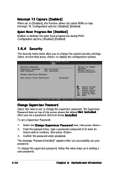
... security settings. The message "Password Installed" appears after you successfully set a Supervisor Password: 1. To set your password. After you to change the supervisor password, follow the same steps as in setting a user password. 5-32 Chapter 5: Motherboard information Select Screen Select Item +- Configuration options: [Disabled] [Enabled] Quiet Boot Progress Bar [Disabled] Enables or disables the quiet boot progress bar during POST. The Supervisor Password item on top of at least six letters and/or numbers, then...
... security settings. The message "Password Installed" appears after you successfully set a Supervisor Password: 1. To set your password. After you to change the supervisor password, follow the same steps as in setting a user password. 5-32 Chapter 5: Motherboard information Select Screen Select Item +- Configuration options: [Disabled] [Enabled] Quiet Boot Progress Bar [Disabled] Enables or disables the quiet boot progress bar during POST. The Supervisor Password item on top of at least six letters and/or numbers, then...
AP1710-E1 English version manual
Page 147
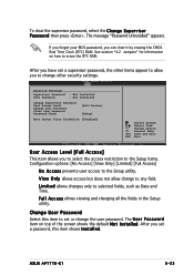
...Time. Security Settings Supervisor Password User Password : Not Installed : Not Installed Change Supervisor Password User Access Level Change User Password Clear User Password Password Check [Full Access] [Setup] Boot Sector Virus Protection [Disabled] Select Screen Select Item +- See section "4.2 Jumpers" for information on top of the screen shows the default N o t I n s t a l l e d. Change Option F1 General Help F10 Save and Exit ESC Exit User Access Level [Full Access] This item allows you to change to the Setup utility. ASUS AP1710-E1 5-33 Change User Password Select this...
...Time. Security Settings Supervisor Password User Password : Not Installed : Not Installed Change Supervisor Password User Access Level Change User Password Clear User Password Password Check [Full Access] [Setup] Boot Sector Virus Protection [Disabled] Select Screen Select Item +- See section "4.2 Jumpers" for information on top of the screen shows the default N o t I n s t a l l e d. Change Option F1 General Help F10 Save and Exit ESC Exit User Access Level [Full Access] This item allows you to change to the Setup utility. ASUS AP1710-E1 5-33 Change User Password Select this...
AP1710-E1 English version manual
Page 157
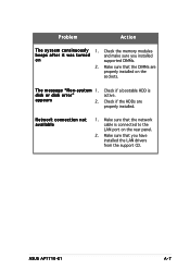
... sure that the DIMMs are properly installed. ASUS AP1710-E1 A-7 Check the memory modules beeps after it was turned and make sure you have installed the LAN drivers from the support CD. Network connection not available 1. Check if a bootable HDD is connected to the LAN port on the rear panel. 2. Problem Action T h e s y s t e m c o n t i n u o u s l y 1. Make sure that the network cable is active. s y s t e m 1. disk or disk error" appears 2. Make sure that you installed on the sockets. Check if the HDDs are properly installed on supported DIMMs. 2.
... sure that the DIMMs are properly installed. ASUS AP1710-E1 A-7 Check the memory modules beeps after it was turned and make sure you have installed the LAN drivers from the support CD. Network connection not available 1. Check if a bootable HDD is connected to the LAN port on the rear panel. 2. Problem Action T h e s y s t e m c o n t i n u o u s l y 1. Make sure that the network cable is active. s y s t e m 1. disk or disk error" appears 2. Make sure that you installed on the sockets. Check if the HDDs are properly installed on supported DIMMs. 2.


