
A8V-E SE User's Manual for English Edition
Page 1
A8V-E SE Motherboard
A8V-E SE Motherboard
A8V-E SE User's Manual for English Edition
Page 3
... Where to find more information viii Conventions used in this guide ix Typography ix A8V-E SE specifications summary x Chapter 1: Product introduction 1.1 Welcome 1-2 1.2 Package contents 1-2 1.3 Special features 1-3 1.3.1 Product highlights 1-3 1.3.2 Innovative ASUS features 1-5 1.4 Before you proceed 1-6 1.5 Motherboard overview 1-7 1.5.1 Placement direction 1-7 1.5.2 Screw holes 1-7 1.5.3 Motherboard layout 1-8 1.6 Central Processing Unit (CPU 1-9 1.6.1 Overview 1-9 1.6.2 Installling the CPU 1-9 1.6.3 Installing the heatsink and fan...
... Where to find more information viii Conventions used in this guide ix Typography ix A8V-E SE specifications summary x Chapter 1: Product introduction 1.1 Welcome 1-2 1.2 Package contents 1-2 1.3 Special features 1-3 1.3.1 Product highlights 1-3 1.3.2 Innovative ASUS features 1-5 1.4 Before you proceed 1-6 1.5 Motherboard overview 1-7 1.5.1 Placement direction 1-7 1.5.2 Screw holes 1-7 1.5.3 Motherboard layout 1-8 1.6 Central Processing Unit (CPU 1-9 1.6.1 Overview 1-9 1.6.2 Installling the CPU 1-9 1.6.3 Installing the heatsink and fan...

A8V-E SE User's Manual for English Edition
Page 7
...Do not place the product in your retailer. If you add a device. • Before connecting or removing signal cables from the motherboard, ensure that all power cables are unplugged. • Seek professional assistance before using an adapter or extension cord. Safety information Electrical safety... extremes. If possible, disconnect all cables are correctly connected and the power cables are connected. Operation safety • Before installing the motherboard and adding devices on a stable surface. • If you are using the product, make sure all power cables from the existing...
...Do not place the product in your retailer. If you add a device. • Before connecting or removing signal cables from the motherboard, ensure that all power cables are unplugged. • Seek professional assistance before using an adapter or extension cord. Safety information Electrical safety... extremes. If possible, disconnect all cables are correctly connected and the power cables are connected. Operation safety • Before installing the motherboard and adding devices on a stable surface. • If you are using the product, make sure all power cables from the existing...
A8V-E SE User's Manual for English Edition
Page 8
... optional documentation, such as warranty flyers, that comes with the motherboard package. ASUS websites The ASUS website provides updated information on the motherboard. • Chapter 2: BIOS setup This chapter tells how to the ASUS contact information. 2. viii About this guide is organized This manual...to perform when installing system components. It also lists the hardware setup procedures that you need when installing and configuring the motherboard. How this guide This user guide contains the information you have been added by your dealer. These documents are also ...
... optional documentation, such as warranty flyers, that comes with the motherboard package. ASUS websites The ASUS website provides updated information on the motherboard. • Chapter 2: BIOS setup This chapter tells how to the ASUS contact information. 2. viii About this guide is organized This manual...to perform when installing system components. It also lists the hardware setup procedures that you need when installing and configuring the motherboard. How this guide This user guide contains the information you have been added by your dealer. These documents are also ...

A8V-E SE User's Manual for English Edition
Page 13
This chapter describes the motherboard features and the new technologies it supports. 1Product introduction ASUS A8V-E SE 1-1
This chapter describes the motherboard features and the new technologies it supports. 1Product introduction ASUS A8V-E SE 1-1

A8V-E SE User's Manual for English Edition
Page 14
Before you for the following items. Motherboard ASUS A8V-E SE motherboard Cables 2 x Serial ATA signal cables 2 x Serial ATA power cables 1 x Ultra DMA/133 cables 1 x 40-conductor IDE cable 1 x Floppy disk drive cable Accessories I/O shield A p p l i c a t i o n C D s ASUS motherboard support CD D o c u m e n t a t i o n User guide If any of ASUS quality motherboards! 1.1 Welcome! Thank you start installing the motherboard, and hardware devices on it another standout in...
Before you for the following items. Motherboard ASUS A8V-E SE motherboard Cables 2 x Serial ATA signal cables 2 x Serial ATA power cables 1 x Ultra DMA/133 cables 1 x 40-conductor IDE cable 1 x Floppy disk drive cable Accessories I/O shield A p p l i c a t i o n C D s ASUS motherboard support CD D o c u m e n t a t i o n User guide If any of ASUS quality motherboards! 1.1 Welcome! Thank you start installing the motherboard, and hardware devices on it another standout in...
A8V-E SE User's Manual for English Edition
Page 15
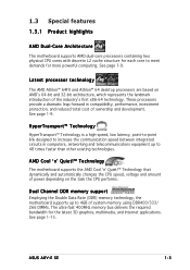
... Technology The motherboard supports the AMD Cool 'n' Quiet!™ Technology that dynamically and automatically changes the CPU speed, voltage and amount of system memory using DDR400/333/ 266 DIMMs. The ultra-fast 400MHz memory bus delivers the required bandwidth for more powerful computing. ASUS A8V-E SE 1-3 These processors...CPU performs. Dual Channel DDR memory support Employing the Double Data Rate (DDR) memory technology, the motherboard supports up to 48 times faster than other existing technologies. 1.3 Special features 1.3.1 Product highlights AMD Dual-Core Architecture The...
... Technology The motherboard supports the AMD Cool 'n' Quiet!™ Technology that dynamically and automatically changes the CPU speed, voltage and amount of system memory using DDR400/333/ 266 DIMMs. The ultra-fast 400MHz memory bus delivers the required bandwidth for more powerful computing. ASUS A8V-E SE 1-3 These processors...CPU performs. Dual Channel DDR memory support Employing the Double Data Rate (DDR) memory technology, the motherboard supports up to 48 times faster than other existing technologies. 1.3 Special features 1.3.1 Product highlights AMD Dual-Core Architecture The...

A8V-E SE User's Manual for English Edition
Page 16
... the voltage levels to prevent overheating and damage. See section "2.5.4 Hardware Monitor" on USB 2.0. Serial ATA technology The motherboard supports Serial ATA technology through the S/PDIF interfaces on the rear panel. The system fan rotations per minute (RPM) is... See page 1-23 for critical components. This high speed interface is backward compatible with existing PCI specifications. USB 2.0 technology The motherboard implements the Universal Serial Bus (USB) 2.0 specification, dramatically increasing the connection speed from the 12 Mbps bandwidth on USB 1.1...
... the voltage levels to prevent overheating and damage. See section "2.5.4 Hardware Monitor" on USB 2.0. Serial ATA technology The motherboard supports Serial ATA technology through the S/PDIF interfaces on the rear panel. The system fan rotations per minute (RPM) is... See page 1-23 for critical components. This high speed interface is backward compatible with existing PCI specifications. USB 2.0 technology The motherboard implements the Universal Serial Bus (USB) 2.0 specification, dramatically increasing the connection speed from the 12 Mbps bandwidth on USB 1.1...

A8V-E SE User's Manual for English Edition
Page 17
... cable faults and shorts. Precision Tweaker Designed for optimized graphics performance. See page 2-21 for details. See page 2-32 for details. ASUS A8V-E SE 1-5 CrashFree BIOS 2 This feature allows you to gradually increase the CPU and memory voltage to the LAN (RJ-45) port... are corrupted. See details on page 2-6. With this feature allows you to restore the original BIOS data from the support CD in the motherboard allows you to adjust the PCI Express graphics frequency according to 100 meters at 1 meter accuracy. This protection eliminates the need to ensure ...
... cable faults and shorts. Precision Tweaker Designed for optimized graphics performance. See page 2-21 for details. See page 2-32 for details. ASUS A8V-E SE 1-5 CrashFree BIOS 2 This feature allows you to gradually increase the CPU and memory voltage to the LAN (RJ-45) port... are corrupted. See details on page 2-6. With this feature allows you to restore the original BIOS data from the support CD in the motherboard allows you to adjust the PCI Express graphics frequency according to 100 meters at 1 meter accuracy. This protection eliminates the need to ensure ...

A8V-E SE User's Manual for English Edition
Page 18
...place it on a grounded antistatic pad or in soft-off or the p o w e r c o r d i s d e t a c h e d f r o m t h e p o w e r s u p p l y . Onboard LEDs The motherboard comes with the component. • Before you should shut down the system and unplug the power cable before removing or plugging in any component, ensure...mode, or in the bag that came with a green standby power LED that lights up to the motherboard, peripherals, and/or components. A8V-E SE ® A8V-E SE Onboard LED SB_PWR ON Standby Power OFF Powered Off 1-6 Chapter 1: Product introduction This is switched off mode...
...place it on a grounded antistatic pad or in soft-off or the p o w e r c o r d i s d e t a c h e d f r o m t h e p o w e r s u p p l y . Onboard LEDs The motherboard comes with the component. • Before you should shut down the system and unplug the power cable before removing or plugging in any component, ensure...mode, or in the bag that came with a green standby power LED that lights up to the motherboard, peripherals, and/or components. A8V-E SE ® A8V-E SE Onboard LED SB_PWR ON Standby Power OFF Powered Off 1-6 Chapter 1: Product introduction This is switched off mode...

A8V-E SE User's Manual for English Edition
Page 19
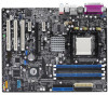
... into the holes indicated by circles to secure the motherboard to do so can damage the motherboard. Failure to the chassis. The edge with external ports goes to unplug the power cord before installing or removing the motherboard. Do not overtighten the screws! Place this side... towards the rear of the chassis as indicated in the correct orientation. 1.5 Motherboard overview Before you place it . Make sure to the rear part of the chassis A8V-E SE ® ASUS A8V-E SE 1-7
... into the holes indicated by circles to secure the motherboard to do so can damage the motherboard. Failure to the chassis. The edge with external ports goes to unplug the power cord before installing or removing the motherboard. Do not overtighten the screws! Place this side... towards the rear of the chassis as indicated in the correct orientation. 1.5 Motherboard overview Before you place it . Make sure to the rear part of the chassis A8V-E SE ® ASUS A8V-E SE 1-7
A8V-E SE User's Manual for English Edition
Page 21
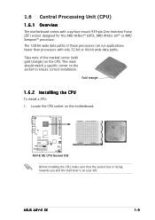
... paths of the marked corner (with only 32-bit or 64-bit wide data paths. Locate the CPU socket on the CPU. ASUS A8V-E SE 1-9 1.6 Central Processing Unit (CPU) 1.6.1 Overview The motherboard comes with a surface mount 939-pin Zero Insertion Force (ZIF) socket designed for the AMD Athlon™ 64FX, AMD Athlon 64™...
... paths of the marked corner (with only 32-bit or 64-bit wide data paths. Locate the CPU socket on the CPU. ASUS A8V-E SE 1-9 1.6 Central Processing Unit (CPU) 1.6.1 Overview The motherboard comes with a surface mount 939-pin Zero Insertion Force (ZIF) socket designed for the AMD Athlon™ 64FX, AMD Athlon 64™...

A8V-E SE User's Manual for English Edition
Page 23
...already installed on the motherboard upon purchase. • You do not match the CPU documentation, follow the latter. If the instructions in this section do not have to the CPU heatsink or CPU before you use only qualified heatsink and fan assembly. ASUS A8V-E SE 1-11 CPU Fan ... module base. • The retention module base is properly applied to remove the retention module base when installing the CPU or installing other motherboard components. • If you purchased a separate CPU heatsink and fan assembly, make sure that you install the heatsink and fan assembly. ...
...already installed on the motherboard upon purchase. • You do not match the CPU documentation, follow the latter. If the instructions in this section do not have to the CPU heatsink or CPU before you use only qualified heatsink and fan assembly. ASUS A8V-E SE 1-11 CPU Fan ... module base. • The retention module base is properly applied to remove the retention module base when installing the CPU or installing other motherboard components. • If you purchased a separate CPU heatsink and fan assembly, make sure that you install the heatsink and fan assembly. ...

A8V-E SE User's Manual for English Edition
Page 24
... to the retention module base. Hardware monitoring errors can occur if you cannot snap the retention bracket in place. CPU_FAN Rotation +12V GND A8V-E SE ® A8V-E SE CPU Fan connector Do not forget to the retention module base. 1 2 3 4 5 3. Make sure that the retention bracket is... the heatsink and fan to plug this connector. 1-12 Chapter 1: Product introduction Push down the retention bracket lock on the motherboard labeled CPU_FAN. A clicking sound denotes that the fan and heatsink assembly perfectly fits the retention mechanism module base, otherwise you ...
... to the retention module base. Hardware monitoring errors can occur if you cannot snap the retention bracket in place. CPU_FAN Rotation +12V GND A8V-E SE ® A8V-E SE CPU Fan connector Do not forget to the retention module base. 1 2 3 4 5 3. Make sure that the retention bracket is... the heatsink and fan to plug this connector. 1-12 Chapter 1: Product introduction Push down the retention bracket lock on the motherboard labeled CPU_FAN. A clicking sound denotes that the fan and heatsink assembly perfectly fits the retention mechanism module base, otherwise you ...

A8V-E SE User's Manual for English Edition
Page 25
...8226; Due to chipset limitation, DIMM modules with 128 Mb memory chips or double-sided x16 memory chips are not supported in this motherboard. • Due to chipset resource allocation, the system may install 64MB, 128MB, 256 MB, 512 MB and 1 GB unbuffered...memory modules from the same vendor. 1.7 System memory 1.7.1 Overview The motherboard comes with the same CAS latency. ASUS A8V-E SE 1-13 The following figure illustrates the location of the sockets: DIMM_A1 DIMM_A2 DIMM_B1 DIMM_B2 A8V-E SE ® A8V-E SE 184-pin DDR DIMM sockets Channel Channel A Channel B Sockets DIMM_A1 ...
...8226; Due to chipset limitation, DIMM modules with 128 Mb memory chips or double-sided x16 memory chips are not supported in this motherboard. • Due to chipset resource allocation, the system may install 64MB, 128MB, 256 MB, 512 MB and 1 GB unbuffered...memory modules from the same vendor. 1.7 System memory 1.7.1 Overview The motherboard comes with the same CAS latency. ASUS A8V-E SE 1-13 The following figure illustrates the location of the sockets: DIMM_A1 DIMM_A2 DIMM_B1 DIMM_B2 A8V-E SE ® A8V-E SE 184-pin DDR DIMM sockets Channel Channel A Channel B Sockets DIMM_A1 ...

A8V-E SE User's Manual for English Edition
Page 28
... place and the DIMM is keyed with extra force. 2. 1.7.3 Installing a DIMM Make sure to remove a DIMM. 2 1. Simultaneously press the retaining clips outward to both the motherboard and the components. 1. Firmly insert the DIMM into a socket to avoid damaging the DIMM. 3 3. Remove the DIMM from the socket. 1-16 Chapter 1: Product introduction Align...
... place and the DIMM is keyed with extra force. 2. 1.7.3 Installing a DIMM Make sure to remove a DIMM. 2 1. Simultaneously press the retaining clips outward to both the motherboard and the components. 1. Firmly insert the DIMM into a socket to avoid damaging the DIMM. 3 3. Remove the DIMM from the socket. 1-16 Chapter 1: Product introduction Align...
A8V-E SE User's Manual for English Edition
Page 29
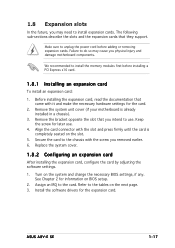
.... 1.8.1 Installing an expansion card To install an expansion card: 1. We recommended to the tables on BIOS setup. 2. Remove the system unit cover (if your motherboard is completely seated on the system and change the necessary BIOS settings, if any. Replace the system cover. 1.8.2 Configuring an expansion card After installing the... 2 for later use . Align the card connector with the screw you intend to the card. Assign an IRQ to use . 4. Turn on the slot. 5. ASUS A8V-E SE 1-17 1.8 Expansion slots In the future, you physical injury and damage motherboard components.
.... 1.8.1 Installing an expansion card To install an expansion card: 1. We recommended to the tables on BIOS setup. 2. Remove the system unit cover (if your motherboard is completely seated on the system and change the necessary BIOS settings, if any. Replace the system cover. 1.8.2 Configuring an expansion card After installing the... 2 for later use . Align the card connector with the screw you intend to the card. Assign an IRQ to use . 4. Turn on the slot. 5. ASUS A8V-E SE 1-17 1.8 Expansion slots In the future, you physical injury and damage motherboard components.

A8V-E SE User's Manual for English Edition
Page 30
...* IRQ holder for PCI steering* PS/2 Compatible Mouse Port* Numeric Data Processor Primary IDE Channel Secondary IDE Channel * These IRQs are usually available for this motherboard PCI slot 1 PCI slot 2 PCI slot 3 PCI E x1 slot 1 PCI E x1 slot 2 PCI E x16 slot Onboard USB controller 1 Onboard USB controller 2 Onboard USB controller 3 Onboard...
...* IRQ holder for PCI steering* PS/2 Compatible Mouse Port* Numeric Data Processor Primary IDE Channel Secondary IDE Channel * These IRQs are usually available for this motherboard PCI slot 1 PCI slot 2 PCI slot 3 PCI E x1 slot 1 PCI E x1 slot 2 PCI E x16 slot Onboard USB controller 1 Onboard USB controller 2 Onboard USB controller 3 Onboard...

A8V-E SE User's Manual for English Edition
Page 31
ASUS A8V-E SE 1-19 1.8.4 PCI slots The PCI slots support cards such as a LAN card, SCSI card, USB card, and other cards that comply with PCI specifications. The figure shows a LAN card installed on a PCI slot. 1.8.5 PCI Express x16 slot This motherboard supports PCI Express x16 graphic cards that comply with the PCI ... on the PCI Express x1 slot. The figure shows a network card installed on the PCI Express x16 slot. 1.8.6 PCI Express x1 slot This motherboard supports PCI Express x1 network cards, SCSI cards and other cards that comply with the PCI Express specifications.
ASUS A8V-E SE 1-19 1.8.4 PCI slots The PCI slots support cards such as a LAN card, SCSI card, USB card, and other cards that comply with PCI specifications. The figure shows a LAN card installed on a PCI slot. 1.8.5 PCI Express x16 slot This motherboard supports PCI Express x16 graphic cards that comply with the PCI ... on the PCI Express x1 slot. The figure shows a network card installed on the PCI Express x16 slot. 1.8.6 PCI Express x1 slot This motherboard supports PCI Express x1 network cards, SCSI cards and other cards that comply with the PCI Express specifications.

A8V-E SE User's Manual for English Edition
Page 36
... the IDE connector is removed to PIN 1. 1-24 Chapter 1: Product introduction SEC_IDE PRI_IDE A8V-E SE ® A8V-E SE IDE connectors PIN 1 NOTE: Orient the red markings (usually zigzag) on the IDE ribbon cable to match the covered hole on the motherboard, a black connector for an Ultra DMA 133/100/66 IDE slave device (optical drive...
... the IDE connector is removed to PIN 1. 1-24 Chapter 1: Product introduction SEC_IDE PRI_IDE A8V-E SE ® A8V-E SE IDE connectors PIN 1 NOTE: Orient the red markings (usually zigzag) on the IDE ribbon cable to match the covered hole on the motherboard, a black connector for an Ultra DMA 133/100/66 IDE slave device (optical drive...


