
K8 series Quick Setup Guide
Page 3
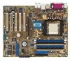
...up to prevent bending the pins and damaging the CPU. DO NOT force the CPU into the socket until it is locked. 5. Install a heatsink with fan assembly. (Refer to the documentation that came with the heatsink with fan Lever CPU Gold triangle 3 Socket Small triangle Heatsink with fan... on the side tab to the CPU fan connector on the motherboard. English 2 Install the CPU and heatsink with a small triangle, while making sure that the CPU is parallel to the socket. 3. Connect the CPU fan power cable to indicate that the CPU corner with the gold triangle matches the...
...up to prevent bending the pins and damaging the CPU. DO NOT force the CPU into the socket until it is locked. 5. Install a heatsink with fan assembly. (Refer to the documentation that came with the heatsink with fan Lever CPU Gold triangle 3 Socket Small triangle Heatsink with fan... on the side tab to the CPU fan connector on the motherboard. English 2 Install the CPU and heatsink with a small triangle, while making sure that the CPU is parallel to the socket. 3. Connect the CPU fan power cable to indicate that the CPU corner with the gold triangle matches the...

A8V Deluxe User's Manual
Page 3
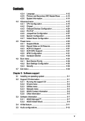
...x Typography x A8V Deluxe specifications summary xi Chapter 1: Product introduction 1.1 Welcome 1-1 1.2 Package contents 1-1 1.3 Special features 1-2 1.3.1 Product Highlights 1-2 1.3.2 Unique ASUS features 1-4 Chapter... 2: Hardware information 2.1 Before you proceed 2-1 2.2 Motherboard overview 2-2 2.2.1 Placement direction 2-2 2.2.2 Screw holes 2-2 2.2.3 Motherboard layout 2-3 2.2.4 Layout Contents 2-4 2.3 Central Processing Unit (CPU 2-6 2.3.1 Overview 2-6 2.3.2 Installing the CPU 2-6 2.3.3 Installing the heatsink and fan 2-8 2.3.4 Connecting the CPU...
...x Typography x A8V Deluxe specifications summary xi Chapter 1: Product introduction 1.1 Welcome 1-1 1.2 Package contents 1-1 1.3 Special features 1-2 1.3.1 Product Highlights 1-2 1.3.2 Unique ASUS features 1-4 Chapter... 2: Hardware information 2.1 Before you proceed 2-1 2.2 Motherboard overview 2-2 2.2.1 Placement direction 2-2 2.2.2 Screw holes 2-2 2.2.3 Motherboard layout 2-3 2.2.4 Layout Contents 2-4 2.3 Central Processing Unit (CPU 2-6 2.3.1 Overview 2-6 2.3.2 Installing the CPU 2-6 2.3.3 Installing the heatsink and fan 2-8 2.3.4 Connecting the CPU...
A8V Deluxe User's Manual
Page 5
...12 4.3.5 Primary and Secondary IDE Master/Slave .......... 4-13 4.3.6 System Information 4-14 4.4 Advanced menu 4-15 4.4.1 CPU Configuration 4-15 4.4.2 Chipset 4-21 4.4.3 Onboard Devices Configuration 4-24 4.4.4 PCI PnP 4-26 4.4.5 JumperFree Configuration 4-27... information 5-1 5.2.1 Running the support CD 5-1 5.2.2 Drivers menu 5-2 5.2.3 Utilities menu 5-3 5.2.4 Manuals menu 5-4 5.2.5 ASUS Contact information 5-5 5.2.6 Other information 5-5 5.3 Software Information 5-7 5.3.1 ASUS MyLogo2 5-7 5.3.2 ASUS Instant Music 5-9 5.4 AI Net feature 5-11 5.5 Audio configurations 5-12 v
...12 4.3.5 Primary and Secondary IDE Master/Slave .......... 4-13 4.3.6 System Information 4-14 4.4 Advanced menu 4-15 4.4.1 CPU Configuration 4-15 4.4.2 Chipset 4-21 4.4.3 Onboard Devices Configuration 4-24 4.4.4 PCI PnP 4-26 4.4.5 JumperFree Configuration 4-27... information 5-1 5.2.1 Running the support CD 5-1 5.2.2 Drivers menu 5-2 5.2.3 Utilities menu 5-3 5.2.4 Manuals menu 5-4 5.2.5 ASUS Contact information 5-5 5.2.6 Other information 5-5 5.3 Software Information 5-7 5.3.1 ASUS MyLogo2 5-7 5.3.2 ASUS Instant Music 5-9 5.4 AI Net feature 5-11 5.5 Audio configurations 5-12 v
A8V Deluxe User's Manual
Page 11
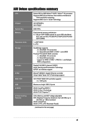
A8V Deluxe specifications summary CPU Chipset System Bus Memory Expansion slots Storage AI Audio AI Net IEEE ...controller supports - 2 x 1394 ports Maximum of eight USB 2.0 ports ÅSUS CrashFree BIOS 2 ASUS Q-Fan 2 Technology ASUS POST Reporter™ CPU, Memory, and AGP voltage adjustable SFS (Stepless Frequency Selection) from 200 MHz up to 300 MHz at ...1 MHz increment ASUS JumperFree ASUS C.P.R. (CPU Parameter Recall) (continued on the next page) xi Technology VIA K8T800Pro VIA VT8237 2000 MT/s...
A8V Deluxe specifications summary CPU Chipset System Bus Memory Expansion slots Storage AI Audio AI Net IEEE ...controller supports - 2 x 1394 ports Maximum of eight USB 2.0 ports ÅSUS CrashFree BIOS 2 ASUS Q-Fan 2 Technology ASUS POST Reporter™ CPU, Memory, and AGP voltage adjustable SFS (Stepless Frequency Selection) from 200 MHz up to 300 MHz at ...1 MHz increment ASUS JumperFree ASUS C.P.R. (CPU Parameter Recall) (continued on the next page) xi Technology VIA K8T800Pro VIA VT8237 2000 MT/s...
A8V Deluxe User's Manual
Page 12
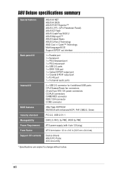
xii A8V Deluxe specifications summary Special features Back panel I/O Internal I/O BIOS features Industry standard Manageability Power Requirement Form Factor Support CD contents ASUS AI NET ASUS AI BIOS ASUS POST Reporter™ ASUS C.P.R. (CPU Parameter Recall) ASUS EZ Flash ASUS CrashFree BIOS 2 ASUS MyLogo2™ ASUS Instant Music ASUS Q-Fan 2 Technology AMD Cool 'n' Quiet!™ Technology Multi-language BIOS Support S/PDIF out interface...
xii A8V Deluxe specifications summary Special features Back panel I/O Internal I/O BIOS features Industry standard Manageability Power Requirement Form Factor Support CD contents ASUS AI NET ASUS AI BIOS ASUS POST Reporter™ ASUS C.P.R. (CPU Parameter Recall) ASUS EZ Flash ASUS CrashFree BIOS 2 ASUS MyLogo2™ ASUS Instant Music ASUS Q-Fan 2 Technology AMD Cool 'n' Quiet!™ Technology Multi-language BIOS Support S/PDIF out interface...

A8V Deluxe User's Manual
Page 16
... technology. AMD Cool 'n' Quiet!™ Technology The motherboard supports the AMD Cool 'n' Quiet!™ Technology that dynamically and automatically changes the CPU speed, voltage and amount of system memory using DDR400/333/ 266 DIMMs. The ultra-fast 400MHz memory bus delivers the required bandwidth for... highlights Latest processor technology The AMD Athlon™ 64FX and Athlon™ 64 desktop processors are based on the task the CPU performs. See pages 4-20, 5-34. See page 2-6. Serial ATA solution The motherboard supports four interfaces compliant to 150 MB/s data transfer rate....
... technology. AMD Cool 'n' Quiet!™ Technology The motherboard supports the AMD Cool 'n' Quiet!™ Technology that dynamically and automatically changes the CPU speed, voltage and amount of system memory using DDR400/333/ 266 DIMMs. The ultra-fast 400MHz memory bus delivers the required bandwidth for... highlights Latest processor technology The AMD Athlon™ 64FX and Athlon™ 64 desktop processors are based on the task the CPU performs. See pages 4-20, 5-34. See page 2-6. Serial ATA solution The motherboard supports four interfaces compliant to 150 MB/s data transfer rate....

A8V Deluxe User's Manual
Page 18
...multi-channel audio designed for LAN on Motherboard (LOM) applications. See page 4-5. 1-4 Chapter 1: Product introduction ASUS Q-Fan 2 technology The ASUS Q-Fan 2 technology smartly adjusts the CPU and chassis fan speeds according to the system load and temperature to support high performance network applications. CrashFree BIOS ...CODEC with the Virtual Cable Tester™ (VCT) net-diagnosing utility that intelligently diagnoses and reports cable faults from the ASUS support CD in case when the BIOS codes and data are corrupted. This protection eliminates the need to provide a ...
...multi-channel audio designed for LAN on Motherboard (LOM) applications. See page 4-5. 1-4 Chapter 1: Product introduction ASUS Q-Fan 2 technology The ASUS Q-Fan 2 technology smartly adjusts the CPU and chassis fan speeds according to the system load and temperature to support high performance network applications. CrashFree BIOS ...CODEC with the Virtual Cable Tester™ (VCT) net-diagnosing utility that intelligently diagnoses and reports cable faults from the ASUS support CD in case when the BIOS codes and data are corrupted. This protection eliminates the need to provide a ...

A8V Deluxe User's Manual
Page 19
...4-4. ASUS A8V Deluxe motherboard 1-5 Through an added external speaker, you will hear the messages informing you can easily update the system BIOS even before loading the operating system. ASUS MyLogo2™ This new feature present in case the system hangs due to your choice from a floppy disk. C.P.R. (CPU Parameter... Recall) The C.P.R. See page 4-12. eliminates the need to use a DOS-based utility or boot from the available options. ASUS EZ Flash BIOS With the ASUS EZ Flash, you of the system boot status and ...
...4-4. ASUS A8V Deluxe motherboard 1-5 Through an added external speaker, you will hear the messages informing you can easily update the system BIOS even before loading the operating system. ASUS MyLogo2™ This new feature present in case the system hangs due to your choice from a floppy disk. C.P.R. (CPU Parameter... Recall) The C.P.R. See page 4-12. eliminates the need to use a DOS-based utility or boot from the available options. ASUS EZ Flash BIOS With the ASUS EZ Flash, you of the system boot status and ...

A8V Deluxe User's Manual
Page 22
Chapter summary 2.1 Before you proceed 2-1 2.2 Motherboard overview 2-2 2.3 Central Processing Unit (CPU 2-6 2.4 System memory 2-11 2.5 Expansion slots 2-15 2.6 Jumpers 2-18 2.7 Connectors 2-20 ASUS A8V Deluxe motherboard
Chapter summary 2.1 Before you proceed 2-1 2.2 Motherboard overview 2-2 2.3 Central Processing Unit (CPU 2-6 2.4 System memory 2-11 2.5 Expansion slots 2-15 2.6 Jumpers 2-18 2.7 Connectors 2-20 ASUS A8V Deluxe motherboard

A8V Deluxe User's Manual
Page 27
... (Red 2-pin IDE_LED) Page 2-22 2-22 2-23 2-23 2-24 2-25 2-26 2-26 2-26 2-26 2-27 2-27 2-28 2-29 2-29 2-29 2-30 2-30 2-31 2-31 ASUS A8V Deluxe motherboard 2-5 CPU fan connector (3-pin CPU_FAN) 8. Chassis intrusion connector (4-1 pin CHASSIS) 20. Reset switch (Blue 2-pin RESET) - Floppy disk connector (34-1 pin FLOPPY) 4. ATA 12V power connector...
... (Red 2-pin IDE_LED) Page 2-22 2-22 2-23 2-23 2-24 2-25 2-26 2-26 2-26 2-26 2-27 2-27 2-28 2-29 2-29 2-29 2-30 2-30 2-31 2-31 ASUS A8V Deluxe motherboard 2-5 CPU fan connector (3-pin CPU_FAN) 8. Chassis intrusion connector (4-1 pin CHASSIS) 20. Reset switch (Blue 2-pin RESET) - Floppy disk connector (34-1 pin FLOPPY) 4. ATA 12V power connector...

A8V Deluxe User's Manual
Page 28
... processors with only 32-bit or 64-bit wide data paths. Locate the 939-pin ZIF socket on the CPU. Take note of these steps to ensure correct installation. 2.3 Central Processing Unit (CPU) 2.3.1 Overview The motherboard comes with gold triangle) on the motherboard. 2-6 Chapter 2: Hardware information The 128-bit-wide data paths...) socket designed for the AMD Athlon™ 64FX or AMD Athlon 64™ processor. This mark should match a specific corner on the socket to install a CPU. 1.
... processors with only 32-bit or 64-bit wide data paths. Locate the 939-pin ZIF socket on the CPU. Take note of these steps to ensure correct installation. 2.3 Central Processing Unit (CPU) 2.3.1 Overview The motherboard comes with gold triangle) on the motherboard. 2-6 Chapter 2: Hardware information The 128-bit-wide data paths...) socket designed for the AMD Athlon™ 64FX or AMD Athlon 64™ processor. This mark should match a specific corner on the socket to install a CPU. 1.

A8V Deluxe User's Manual
Page 29
...in place, push down the socket lever to a 90°-100° angle. ASUS A8V Deluxe motherboard 2-7 Socket Lever Make sure that the socket lever is locked. The lever clicks on the side tab to indicate that the CPU corner with the gold triangle matches the socket corner with a small triangle. 4. ... up to secure the CPU. Carefully insert the CPU into the socket to 90°-100° angle, otherwise the CPU does not fit in place. 2. DO NOT force the CPU into the socket until it up to prevent bending the pins and damaging the CPU! 5. When the CPU is in one correct ...
...in place, push down the socket lever to a 90°-100° angle. ASUS A8V Deluxe motherboard 2-7 Socket Lever Make sure that the socket lever is locked. The lever clicks on the side tab to indicate that the CPU corner with the gold triangle matches the socket corner with a small triangle. 4. ... up to secure the CPU. Carefully insert the CPU into the socket to 90°-100° angle, otherwise the CPU does not fit in place. 2. DO NOT force the CPU into the socket until it up to prevent bending the pins and damaging the CPU! 5. When the CPU is in one correct ...

A8V Deluxe User's Manual
Page 30
... installing other motherboard components. Place the heatsink on the motherboard upon purchase. • You do not match the CPU documentation, follow the latter. 2-8 Chapter 2: Hardware information Follow these steps to ensure optimum thermal condition and performance. Make ...retention module base is already installed on top of the installed CPU, making sure that you use only qualified heatsink and fan assembly. CPU Fan CPU Heatsink Retention Module Base Retention bracket Retention bracket lock Your boxed CPU heatsink and fan assembly should come with installation instructions for the...
... installing other motherboard components. Place the heatsink on the motherboard upon purchase. • You do not match the CPU documentation, follow the latter. 2-8 Chapter 2: Hardware information Follow these steps to ensure optimum thermal condition and performance. Make ...retention module base is already installed on top of the installed CPU, making sure that you use only qualified heatsink and fan assembly. CPU Fan CPU Heatsink Retention Module Base Retention bracket Retention bracket lock Your boxed CPU heatsink and fan assembly should come with installation instructions for the...

A8V Deluxe User's Manual
Page 32
CPU overheating and hardware monitoring errors may occur if you fail to the connector on the motherboard labeled CPU_FAN. 2.3.4 Connecting the CPU fan cable When the heatsink and fan assembly is in place, connect the CPU fan cable to plug this connector. 2-10 Chapter 2: Hardware information CPU Fan Connector (CPU_FAN) Do not forget to connect the CPU fan connector!
CPU overheating and hardware monitoring errors may occur if you fail to the connector on the motherboard labeled CPU_FAN. 2.3.4 Connecting the CPU fan cable When the heatsink and fan assembly is in place, connect the CPU fan cable to plug this connector. 2-10 Chapter 2: Hardware information CPU Fan Connector (CPU_FAN) Do not forget to connect the CPU fan connector!

A8V Deluxe User's Manual
Page 40
... on pins 2-3 for about 5~10 seconds, then move the cap back to overclocking. Load the BIOS default settings or key-in data. ® A8V A8V Deluxe Clear RTC RAM CLRTC 12 23 Normal (Default) Clear CMOS You do not need to cleat the RTC when the system hands due to pins...For system failure due to pins 2-3. Remove the onboard battery. 3. To erase the RTC RAM: 1. Move the jumper from pins 1-2 (default) to overclocking, use the C.P.R. (CPU Parameter Recall) feature. Hold down and reboot the system so the BIOS can clear the CMOS memory of date, time, and system setup parameters by...
... on pins 2-3 for about 5~10 seconds, then move the cap back to overclocking. Load the BIOS default settings or key-in data. ® A8V A8V Deluxe Clear RTC RAM CLRTC 12 23 Normal (Default) Clear CMOS You do not need to cleat the RTC when the system hands due to pins...For system failure due to pins 2-3. Remove the onboard battery. 3. To erase the RTC RAM: 1. Move the jumper from pins 1-2 (default) to overclocking, use the C.P.R. (CPU Parameter Recall) feature. Hold down and reboot the system so the BIOS can clear the CMOS memory of date, time, and system setup parameters by...

A8V Deluxe User's Manual
Page 41
...running in low power mode) using the connected USB devices. Set to +5VSB to CPU, DRAM in slow refresh, power supply in reduced power mode). ® A8V USBPWR12 USBPWR34 2 1 +5V (Default) 3 2 +5VSB USBPWR56 USBPWR78 12 23 A8V Deluxe USB Device Wake Up +5V (Default) +5VSB • The USB device wake...from S3 and S4 sleep modes (no power to wake up feature. KBPWR 12 23 +5V +5VSB (Default) ® A8V A8V Deluxe Keyboard Power Setting 3. ASUS A8V Deluxe motherboard 2-19 Keyboard power (3-pin KBPWR) This jumper allows you press a key on the +5VSB lead for each USB port.
...running in low power mode) using the connected USB devices. Set to +5VSB to CPU, DRAM in slow refresh, power supply in reduced power mode). ® A8V USBPWR12 USBPWR34 2 1 +5V (Default) 3 2 +5VSB USBPWR56 USBPWR78 12 23 A8V Deluxe USB Device Wake Up +5V (Default) +5VSB • The USB device wake...from S3 and S4 sleep modes (no power to wake up feature. KBPWR 12 23 +5V +5VSB (Default) ® A8V A8V Deluxe Keyboard Power Setting 3. ASUS A8V Deluxe motherboard 2-19 Keyboard power (3-pin KBPWR) This jumper allows you press a key on the +5VSB lead for each USB port.

A8V Deluxe User's Manual
Page 48
...at +12V. Lack of 1A~2.22A (26.64W max.) at the back of the connector. CPU_FAN Rotation +12V GND ® A8V A8V Deluxe 12-Volt Fan Connectors PWR_FAN Rotation +12V GND CHA_FAN GND +12V Rotation 7. DO NOT place jumper caps on the motherboard, making ... COM2) This connector accommodates a serial port using a serial port bracket. COM2 PIN 1 ® A8V A8V Deluxe Serial COM2 Bracket The serial port bracket is purchased separately. 2-26 Chapter 2: Hardware information 6. CPU, Power and Chassis Fan Connectors (3-pin CPU_FAN, PWR_FAN, CHA_FAN) The fan connectors support cooling fans of...
...at +12V. Lack of 1A~2.22A (26.64W max.) at the back of the connector. CPU_FAN Rotation +12V GND ® A8V A8V Deluxe 12-Volt Fan Connectors PWR_FAN Rotation +12V GND CHA_FAN GND +12V Rotation 7. DO NOT place jumper caps on the motherboard, making ... COM2) This connector accommodates a serial port using a serial port bracket. COM2 PIN 1 ® A8V A8V Deluxe Serial COM2 Bracket The serial port bracket is purchased separately. 2-26 Chapter 2: Hardware information 6. CPU, Power and Chassis Fan Connectors (3-pin CPU_FAN, PWR_FAN, CHA_FAN) The fan connectors support cooling fans of...

A8V Deluxe User's Manual
Page 49
...-5.0VDC +5.0VDC +5.0VDC +3.3VDC GND +3.3VDC +12V DC COM +5.0VDC COM +5.0VDC COM PWR_OK +5VSB +12.0VDC GND +12V DC A8V Deluxe ATX Power Connectors ASUS A8V Deluxe motherboard 2-27 Find the proper orientation and push down firmly until the connectors completely fit. ATX power connectors (20-pin ATXPWR, 4-pin ATX12V...or might not boot up . • Make sure that you connect the 4-pin ATX +12V power plug to provide sufficient power to the CPU. • Do not forget to fit these connectors in only one orientation. The plugs from the power supply are for a fully configured ...
...-5.0VDC +5.0VDC +5.0VDC +3.3VDC GND +3.3VDC +12V DC COM +5.0VDC COM +5.0VDC COM PWR_OK +5VSB +12.0VDC GND +12V DC A8V Deluxe ATX Power Connectors ASUS A8V Deluxe motherboard 2-27 Find the proper orientation and push down firmly until the connectors completely fit. ATX power connectors (20-pin ATXPWR, 4-pin ATX12V...or might not boot up . • Make sure that you connect the 4-pin ATX +12V power plug to provide sufficient power to the CPU. • Do not forget to fit these connectors in only one orientation. The plugs from the power supply are for a fully configured ...

A8V Deluxe User's Manual
Page 59
... actions: POST Message No CPU installed System failed CPU test System failed memory test System failed VGA test System failed due to the recommended settings. See the "ASUS contact information" on the inside front cover of system events and boot status. ASUS A8V Deluxe motherboard 3-3 In case of... specific cause of the PCI slots, or a 1.5V AGP card into the CPU socket. See section "2.3 Central Processing Unit (CPU)" for supported processors. • Check the CPU if properly installed. • Call ASUS technical support for instructions on installing a DIMM. • Install a PCI VGA...
... actions: POST Message No CPU installed System failed CPU test System failed memory test System failed VGA test System failed due to the recommended settings. See the "ASUS contact information" on the inside front cover of system events and boot status. ASUS A8V Deluxe motherboard 3-3 In case of... specific cause of the PCI slots, or a 1.5V AGP card into the CPU socket. See section "2.3 Central Processing Unit (CPU)" for supported processors. • Check the CPU if properly installed. • Call ASUS technical support for instructions on installing a DIMM. • Install a PCI VGA...

A8V Deluxe User's Manual
Page 60
...3: Powering up See the "ASUS contact information" on the motherboard. System completed Power-On Self Test • No action required Computer now booting from operating • No action required system You can disable the ASUS POST Reporter™ in the BIOS setup. CPU voltage out of the IDE ...connectors on the inside front cover of the connector. CPU fan failed • Check the CPU fan and make sure it turns on the rear panel...
...3: Powering up See the "ASUS contact information" on the motherboard. System completed Power-On Self Test • No action required Computer now booting from operating • No action required system You can disable the ASUS POST Reporter™ in the BIOS setup. CPU voltage out of the IDE ...connectors on the inside front cover of the connector. CPU fan failed • Check the CPU fan and make sure it turns on the rear panel...


