A8N-VM User's Manual for English Edtion
Page 12
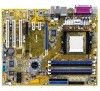
... processor technology The motherboard comes with the list below. 1.2 Package contents Check your motherboard package for the following items. Motherboard Cables Accessory Application CD Documentation ASUS A8N-VM motherboard 1 x Serial ATA signal cable 1 x Serial ATA power cable 1 x Ultra DMA 133/100/66 cable 1 x Floppy disk drive cable I/O shield...
... processor technology The motherboard comes with the list below. 1.2 Package contents Check your motherboard package for the following items. Motherboard Cables Accessory Application CD Documentation ASUS A8N-VM motherboard 1 x Serial ATA signal cable 1 x Serial ATA power cable 1 x Ultra DMA 133/100/66 cable 1 x Floppy disk drive cable I/O shield...
A8N-VM User's Manual for English Edtion
Page 13
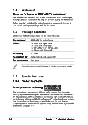
... 0, RAID 1) for thinner, more flexible cables with lower pin count, reduced voltage requirement. See page 1-23 for the latest 3D graphics, multimedia, and Internet applications. ASUS A8N-VM 1-3 PCI Express features point-to-point serial interconnections between devices and allows higher clockspeeds by carrying data in RAID mode. Dual-channel DDR memory support...
... 0, RAID 1) for thinner, more flexible cables with lower pin count, reduced voltage requirement. See page 1-23 for the latest 3D graphics, multimedia, and Internet applications. ASUS A8N-VM 1-3 PCI Express features point-to-point serial interconnections between devices and allows higher clockspeeds by carrying data in RAID mode. Dual-channel DDR memory support...
A8N-VM User's Manual for English Edtion
Page 15
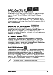
... LED SB_PWR ON Standby Power OFF Powered Off ASUS A8N-VM 1-5 This is a reminder that you should shut down the system and unplug the power cable before handling components to avoid damaging them due to static ...
... LED SB_PWR ON Standby Power OFF Powered Off ASUS A8N-VM 1-5 This is a reminder that you should shut down the system and unplug the power cable before handling components to avoid damaging them due to static ...
A8N-VM User's Manual for English Edtion
Page 17
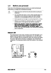
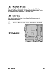
1.5.2 Placement direction When installing the motherboard, make sure that you place it into the chassis in the image below. 1.5.3 Screw holes Place eight (8) screws into the holes indicated by circles to secure the motherboard to the rear part of the chassis ® A8N-VM ASUS A8N-VM 1-7 The edge with external ports goes to the chassis. Do not overtighten the screws! Doing so can damage the motherboard. Place this side towards the rear of the chassis as indicated in the correct orientation.
1.5.2 Placement direction When installing the motherboard, make sure that you place it into the chassis in the image below. 1.5.3 Screw holes Place eight (8) screws into the holes indicated by circles to secure the motherboard to the rear part of the chassis ® A8N-VM ASUS A8N-VM 1-7 The edge with external ports goes to the chassis. Do not overtighten the screws! Doing so can damage the motherboard. Place this side towards the rear of the chassis as indicated in the correct orientation.
A8N-VM User's Manual for English Edtion
Page 19
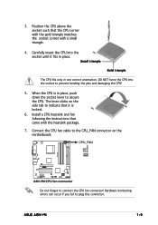
... to the CPU_FAN connector on the side tab to connect the CPU fan connector! ASUS A8N-VM 1-9 3. Hardware monitoring errors can occur if you fail to prevent bending the pins and damaging the CPU! 5. CPU_FAN A8N-VM GND +12V Rotation ® A8N-VM CPU fan connector Do not forget to indicate that came with a small triangle. 4. Install...
... to the CPU_FAN connector on the side tab to connect the CPU fan connector! ASUS A8N-VM 1-9 3. Hardware monitoring errors can occur if you fail to prevent bending the pins and damaging the CPU! 5. CPU_FAN A8N-VM GND +12V Rotation ® A8N-VM CPU fan connector Do not forget to indicate that came with a small triangle. 4. Install...
A8N-VM User's Manual for English Edtion
Page 21
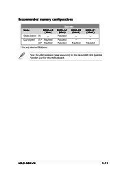
Populated DIMM_B1 (black) - - Dual-channel (1)* Populated (2)* Populated * Use only identical DIMM pairs. Sockets DIMM_A1 (blue) DIMM_B2 (black) Populated - Populated Visit the ASUS website (www.asus.com) for the latest DDR 400 Qualified Vendors List for this motherboard. Recommended memory configurations Mode Single-channel DIMM_A2 (blue) (1)* - ASUS A8N-VM 1-11 Populated Populated -
Populated DIMM_B1 (black) - - Dual-channel (1)* Populated (2)* Populated * Use only identical DIMM pairs. Sockets DIMM_A1 (blue) DIMM_B2 (black) Populated - Populated Visit the ASUS website (www.asus.com) for the latest DDR 400 Qualified Vendors List for this motherboard. Recommended memory configurations Mode Single-channel DIMM_A2 (blue) (1)* - ASUS A8N-VM 1-11 Populated Populated -
A8N-VM User's Manual for English Edtion
Page 23
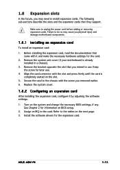
... support. Align the card connector with the screw you removed earlier. 6. See Chapter 2 for the card. 2. Refer to do so may need to the card. ASUS A8N-VM 1-13 Failure to the tables on BIOS setup. 2.
... support. Align the card connector with the screw you removed earlier. 6. See Chapter 2 for the card. 2. Refer to do so may need to the card. ASUS A8N-VM 1-13 Failure to the tables on BIOS setup. 2.
A8N-VM User's Manual for English Edtion
Page 25
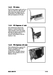
... specifications. 1.8.3 PCI slots The PCI slots support cards such as a LAN card, SCSI card, USB card, and other cards that comply with PCI Express specifications. ASUS A8N-VM 1-15 The figure shows a LAN card installed on a PCI slot. 1.8.4 PCI Express x1 slot This motherboard supports PCI Express x1 network cards, SCSI cards and...
... specifications. 1.8.3 PCI slots The PCI slots support cards such as a LAN card, SCSI card, USB card, and other cards that comply with PCI Express specifications. ASUS A8N-VM 1-15 The figure shows a LAN card installed on a PCI slot. 1.8.4 PCI Express x1 slot This motherboard supports PCI Express x1 network cards, SCSI cards and...
A8N-VM User's Manual for English Edtion
Page 27
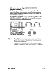
ASUS A8N-VM 1-17 Set to +5VSB to additional USB ports. otherwise, the system will not power up from S1 sleep mode (CPU stopped, DRAM refreshed, system running ... supply that you can provide 500mA on the +5VSB lead for each USB port; USBPW34 3 2 2 1 +5V (Default) +5VSB USBPW12 3 2 2 1 +5V (Default) +5VSB A8N-VM USBPW78 ® USBPW56 246 246 A8N-VM USB device wake-up 135 +5V (Default) 135 +5VSB • The USB device wake-up the computer from S3 and S4 sleep modes...
ASUS A8N-VM 1-17 Set to +5VSB to additional USB ports. otherwise, the system will not power up from S1 sleep mode (CPU stopped, DRAM refreshed, system running ... supply that you can provide 500mA on the +5VSB lead for each USB port; USBPW34 3 2 2 1 +5V (Default) +5VSB USBPW12 3 2 2 1 +5V (Default) +5VSB A8N-VM USBPW78 ® USBPW56 246 246 A8N-VM USB device wake-up 135 +5V (Default) 135 +5VSB • The USB device wake-up the computer from S3 and S4 sleep modes...
A8N-VM User's Manual for English Edtion
Page 29
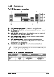
... Blue Lime Pink Headset 2-s p e a k e r Line In Line Out Mic In 4-speake Surround Out Front Speaker Out Mic 6-speaker Surround Out Front Speaker Out Center/Bass ASUS A8N-VM 1-19 1.10 Connectors 1.10.1 Rear panel connectors 1 2 3 4 5 6 10 9 8 7 1 . This port connects a headphone or a speaker. This port allows Gigabit connection to the audio configuration table for...
... Blue Lime Pink Headset 2-s p e a k e r Line In Line Out Mic In 4-speake Surround Out Front Speaker Out Mic 6-speaker Surround Out Front Speaker Out Center/Bass ASUS A8N-VM 1-19 1.10 Connectors 1.10.1 Rear panel connectors 1 2 3 4 5 6 10 9 8 7 1 . This port connects a headphone or a speaker. This port allows Gigabit connection to the audio configuration table for...
A8N-VM User's Manual for English Edtion
Page 31
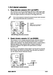
...FDD cable with a jumper cap. FLOPPY NOTE: Orient the red markings on the connector is removed to PIN 1. ® PIN 1 A8N-VM Floppy disk drive connector 2 . The signal is removed or replaced. The chassis intrusion sensor or switch sends a high-level signal to .... By default, the pins labeled "Chassis Signal" and "Ground" are shorted with a covered Pin 5. A8N-VM CHASSIS ® GND (Default) Chassis Signal +5VSB_MB A8N-VM Chassis intrusion connector ASUS A8N-VM 1-21 A8N-VM 1.10.2 Internal connectors 1 . Remove the jumper caps only when you intend to this connector when a ...
...FDD cable with a jumper cap. FLOPPY NOTE: Orient the red markings on the connector is removed to PIN 1. ® PIN 1 A8N-VM Floppy disk drive connector 2 . The signal is removed or replaced. The chassis intrusion sensor or switch sends a high-level signal to .... By default, the pins labeled "Chassis Signal" and "Ground" are shorted with a covered Pin 5. A8N-VM CHASSIS ® GND (Default) Chassis Signal +5VSB_MB A8N-VM Chassis intrusion connector ASUS A8N-VM 1-21 A8N-VM 1.10.2 Internal connectors 1 . Remove the jumper caps only when you intend to this connector when a ...
A8N-VM User's Manual for English Edtion
Page 33
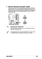
...the standard parallel ATA with 133 MB/s (Ultra DMA/133) GND RSATA_RXN2 RSATA_RXP2 GND RSATA_TXN2 RSATA_TXP2 GND A8N-VM SATA2 ® GND RSATA_RXN1 RSATA_RXP1 GND RSATA_TXN1 RSATA_TXP1 GND A8N-VM SATA connectors SATA1 Important note on how to configure RAID 0, 1, and 0+1, refer to the RAID ...manual in the support CD. For detailed instructions on Serial ATA Install the Windows® 2000 Service Pack 4 or the Windows® XP Service Pack1 before using Serial ATA. ASUS A8N-VM...
...the standard parallel ATA with 133 MB/s (Ultra DMA/133) GND RSATA_RXN2 RSATA_RXP2 GND RSATA_TXN2 RSATA_TXP2 GND A8N-VM SATA2 ® GND RSATA_RXN1 RSATA_RXP1 GND RSATA_TXN1 RSATA_TXP1 GND A8N-VM SATA connectors SATA1 Important note on how to configure RAID 0, 1, and 0+1, refer to the RAID ...manual in the support CD. For detailed instructions on Serial ATA Install the Windows® 2000 Service Pack 4 or the Windows® XP Service Pack1 before using Serial ATA. ASUS A8N-VM...
A8N-VM User's Manual for English Edtion
Page 35
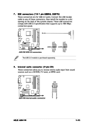
... USB_P8USB_P8+ GND NC USB+5V USB_P6USB_P6+ GND NC USB+5V USB_P7USB_P7+ GND ® A8N-VM USB 2.0 connectors USB56 1 USB+5V USB_P5USB_P5+ GND USB78 1 The USB 2.0 module is purchased separately. 8 . Internal audio connector (4-pin CD) These connectors allow you to 480 ... 2.0 ports. Connect the USB module cable to any of these connectors, then install the module to a slot opening at the back of the system chassis. A8N-VM Left Audio Channel Ground Ground Right Audio Channel CD (black) ® A8N-VM Internal audio connector ASUS A8N-VM 1-25
... USB_P8USB_P8+ GND NC USB+5V USB_P6USB_P6+ GND NC USB+5V USB_P7USB_P7+ GND ® A8N-VM USB 2.0 connectors USB56 1 USB+5V USB_P5USB_P5+ GND USB78 1 The USB 2.0 module is purchased separately. 8 . Internal audio connector (4-pin CD) These connectors allow you to 480 ... 2.0 ports. Connect the USB module cable to any of these connectors, then install the module to a slot opening at the back of the system chassis. A8N-VM Left Audio Channel Ground Ground Right Audio Channel CD (black) ® A8N-VM Internal audio connector ASUS A8N-VM 1-25
A8N-VM User's Manual for English Edtion
Page 37
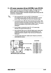
...) These connectors are designed to install additional devices. EATXPWR A8N-VM ATX12V ® GND GND +12V DC +12V DC A8N-VM ATX power connectors +3 Volts -12 Volts Ground PSON# Ground Ground Ground -5 Volts +5 Volts +5 Volts +5 Volts Ground +3 Volts +3 Volts Ground +5 Volts Ground +5 Volts Ground Power OK +5V Standby +12 Volts +12 Volts +3 Volts ASUS A8N-VM 1-27
...) These connectors are designed to install additional devices. EATXPWR A8N-VM ATX12V ® GND GND +12V DC +12V DC A8N-VM ATX power connectors +3 Volts -12 Volts Ground PSON# Ground Ground Ground -5 Volts +5 Volts +5 Volts +5 Volts Ground +3 Volts +3 Volts Ground +5 Volts Ground +5 Volts Ground Power OK +5V Standby +12 Volts +12 Volts +3 Volts ASUS A8N-VM 1-27
A8N-VM User's Manual for English Edtion
Page 41
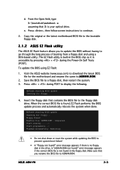
...without having to the floppy disk drive. Copy the original or the latest motherboard BIOS file to the bootable floppy disk. 2.1.2 ASUS EZ Flash utility The ASUS EZ Flash feature allows you rename the BIOS file to display the following. Save the BIOS file to continue. 2. Press ... the BIOS to A 8 N V M . Visit the ASUS website (www.asus.com) to download the latest BIOS file for the motherboard and rename the same to prevent system boot failure! • A "Floppy not found , EZ Flash performs the BIOS update process and automatically reboots the system when done. d. ASUS A8N-VM 2-3
...without having to the floppy disk drive. Copy the original or the latest motherboard BIOS file to the bootable floppy disk. 2.1.2 ASUS EZ Flash utility The ASUS EZ Flash feature allows you rename the BIOS file to display the following. Save the BIOS file to continue. 2. Press ... the BIOS to A 8 N V M . Visit the ASUS website (www.asus.com) to download the latest BIOS file for the motherboard and rename the same to prevent system boot failure! • A "Floppy not found , EZ Flash performs the BIOS update process and automatically reboots the system when done. d. ASUS A8N-VM 2-3
A8N-VM User's Manual for English Edtion
Page 43
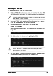
... Reading file ..... Reboot the system from the motherboard support CD to the bootable floppy disk you created earlier. 3. Reading file ..... done A:\> ASUS A8N-VM 2-5 You need to the DOS prompt after the BIOS update process is the latest or the original BIOS file on a piece of paper. A:\>...update the BIOS file using the AFUDOS utility: 1. All rights reserved. done Writing flash .... 0x0008CC00 (9%) Verifying flash .. Visit the ASUS website (www.asus.com) and download the latest BIOS file for the motherboard. Save the BIOS file to prevent system boot failure! 5. Version 1.10 ...
... Reading file ..... Reboot the system from the motherboard support CD to the bootable floppy disk you created earlier. 3. Reading file ..... done A:\> ASUS A8N-VM 2-5 You need to the DOS prompt after the BIOS update process is the latest or the original BIOS file on a piece of paper. A:\>...update the BIOS file using the AFUDOS utility: 1. All rights reserved. done Writing flash .... 0x0008CC00 (9%) Verifying flash .. Visit the ASUS website (www.asus.com) and download the latest BIOS file for the motherboard. Save the BIOS file to prevent system boot failure! 5. Version 1.10 ...
A8N-VM User's Manual for English Edtion
Page 45
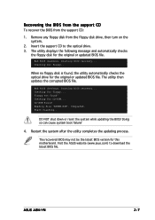
...no floppy disk is found, the utility automatically checks the optical drive for floppy... Bad BIOS checksum. Reading file "A8NVM.ROM". Start flashing... ASUS A8N-VM 2-7 Bad BIOS checksum. Doing so can cause system boot failure! 4. Insert the support CD to download the latest BIOS file. Starting BIOS ...or reset the system while updating the BIOS! Checking for the original or updated BIOS file. CD-ROM found ! Visit the ASUS website (www.asus.com) to the optical drive. 3. Recovering the BIOS from the support CD To recover the BIOS from the floppy disk drive...
...no floppy disk is found, the utility automatically checks the optical drive for floppy... Bad BIOS checksum. Reading file "A8NVM.ROM". Start flashing... ASUS A8N-VM 2-7 Bad BIOS checksum. Doing so can cause system boot failure! 4. Insert the support CD to download the latest BIOS file. Starting BIOS ...or reset the system while updating the BIOS! Checking for the original or updated BIOS file. CD-ROM found ! Visit the ASUS website (www.asus.com) to the optical drive. 3. Recovering the BIOS from the support CD To recover the BIOS from the floppy disk drive...
A8N-VM User's Manual for English Edtion
Page 47
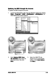
Select the ASUS FTP site t h e I O S f r o m 3. Click N e x t. The ASUS Update main window appears. 2. Launch the ASUS Update utility from the nearest you to avoid network drop-down menu, then click traffic, or click A u t o S e l e c t. Select U p d a t e B I n t e r n e t option from the Windows® desktop by clicking S t a r t > P r o g r a m s > A S U S > A S U S U p d a t e > A S U S U p d a t e. N e x t. ASUS A8N-VM 2-9 Updating the BIOS through the Internet To update the BIOS through the Internet: 1.
Select the ASUS FTP site t h e I O S f r o m 3. Click N e x t. The ASUS Update main window appears. 2. Launch the ASUS Update utility from the nearest you to avoid network drop-down menu, then click traffic, or click A u t o S e l e c t. Select U p d a t e B I n t e r n e t option from the Windows® desktop by clicking S t a r t > P r o g r a m s > A S U S > A S U S U p d a t e > A S U S U p d a t e. N e x t. ASUS A8N-VM 2-9 Updating the BIOS through the Internet To update the BIOS through the Internet: 1.
A8N-VM User's Manual for English Edtion
Page 49
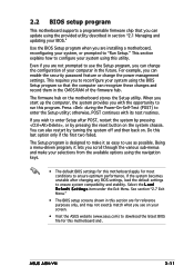
... restart by pressing the reset button on the motherboard stores the Setup utility. For example, you see on . Select the L o a d D e f a u l t S e t t i n g s item under the Exit Menu. ASUS A8N-VM 2-11 Use the BIOS Setup program when you can change the power management settings. You can enable the security password feature or change the configuration... in this section are for this last option only if the first two failed. This section explains how to configure your screen. • Visit the ASUS website (www.asus.com) to enter the Setup utility;
... restart by pressing the reset button on the motherboard stores the Setup utility. For example, you see on . Select the L o a d D e f a u l t S e t t i n g s item under the Exit Menu. ASUS A8N-VM 2-11 Use the BIOS Setup program when you can change the power management settings. You can enable the security password feature or change the configuration... in this section are for this last option only if the first two failed. This section explains how to configure your screen. • Visit the ASUS website (www.asus.com) to enter the Setup utility;
A8N-VM User's Manual for English Edtion
Page 51
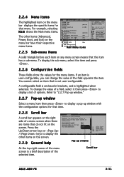
... display a list of the selected item. Primary IDE Master [ST320410A] Primary IDE Slave S520/A] Secondary IDE Master Detected] Secondary IDE Slave Detected] [ASUS CD[Not [Not Enter Tab F1 F10 ESC Select Screen Select Item Go to malfunction. Refer to "2.2.7 Pop-up window." 2.2.7 Pop-up window Select...to Sub Screen Select Field General Help Save and Exit Exit Fivr0s2t.5S8AT(AC)Copyright 1985-20[0N4o,tAmerican Megatrends, Inc. Scroll bar ASUS A8N-VM 2-13 2.2.4 Menu items The highlighted item on the menu bar displays the specific items for that item. 2.2.8 Scroll bar A scroll...
... display a list of the selected item. Primary IDE Master [ST320410A] Primary IDE Slave S520/A] Secondary IDE Master Detected] Secondary IDE Slave Detected] [ASUS CD[Not [Not Enter Tab F1 F10 ESC Select Screen Select Item Go to malfunction. Refer to "2.2.7 Pop-up window." 2.2.7 Pop-up window Select...to Sub Screen Select Field General Help Save and Exit Exit Fivr0s2t.5S8AT(AC)Copyright 1985-20[0N4o,tAmerican Megatrends, Inc. Scroll bar ASUS A8N-VM 2-13 2.2.4 Menu items The highlighted item on the menu bar displays the specific items for that item. 2.2.8 Scroll bar A scroll...


