
A8N-SLI English edition user's manual, version E2068
Page 4
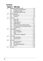
... 2: BIOS setup 2.1 Managing and updating your BIOS 2-2 2.1.1 Creating a bootable floppy disk 2-2 2.1.2 AwardBIOS Flash Utility 2-3 2.1.3 ASUS CrashFree BIOS 2 utility 2-7 2.2 BIOS Setup program 2-8 2.2.1 BIOS menu bar 2-9 2.2.2 Legend bar 2-9 2.3 Main Menu 2-11...12 2.3.6 First, Second, Third, and Fourth SATA Master ..... 2-14 2.3.7 Installed Memory 2-15 2.4 Advanced Menu 2-16 2.4.1 CPU configuration 2-17 2.4.2 Chipset configuration 2-18 2.4.3 PCIPnP 2-20 2.4.4 Onboard device configuration 2-22 2.5 Power Menu 2-28 2.5.1 APM configuration 2-29 2.5.2 Hardware monitor 2-31 2.6 Boot...
... 2: BIOS setup 2.1 Managing and updating your BIOS 2-2 2.1.1 Creating a bootable floppy disk 2-2 2.1.2 AwardBIOS Flash Utility 2-3 2.1.3 ASUS CrashFree BIOS 2 utility 2-7 2.2 BIOS Setup program 2-8 2.2.1 BIOS menu bar 2-9 2.2.2 Legend bar 2-9 2.3 Main Menu 2-11...12 2.3.6 First, Second, Third, and Fourth SATA Master ..... 2-14 2.3.7 Installed Memory 2-15 2.4 Advanced Menu 2-16 2.4.1 CPU configuration 2-17 2.4.2 Chipset configuration 2-18 2.4.3 PCIPnP 2-20 2.4.4 Onboard device configuration 2-22 2.5 Power Menu 2-28 2.5.1 APM configuration 2-29 2.5.2 Hardware monitor 2-31 2.6 Boot...
A8N-SLI English edition user's manual, version E2068
Page 8
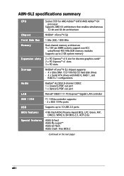
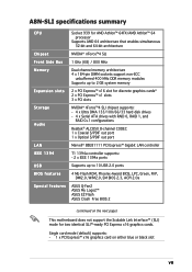
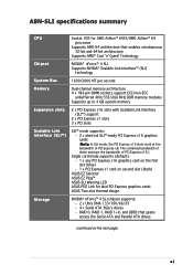
A8N-SLI specifications summary CPU Chipset Front Side Bus Memory Expansion slots Storage Audio LAN IEEE 1394 Socket 939 for AMD Athlon™ 64FX/AMD Athlon™ 64 processor Supports AMD 64 architecture that enables simultaneous 32-bit and 64-bit architecture NVIDIA® nForce™4 SLI 1 GHz (K8) / 800 MHz Dual-channel memory ...BIOS features Special features Supports up to 10 USB 2.0 ports 4 Mb Flash ROM, Phoenix-Award BIOS, LPC, Green, PnP, DMI2.0, WfM2.0, SM BIOS 2.3, ACPI 2.0a ASUS Q-Fan2 ASUS My Logo2™ ASUS EZ Flash ASUS Crash Free BIOS 2 (continued on the next page) viii
A8N-SLI specifications summary CPU Chipset Front Side Bus Memory Expansion slots Storage Audio LAN IEEE 1394 Socket 939 for AMD Athlon™ 64FX/AMD Athlon™ 64 processor Supports AMD 64 architecture that enables simultaneous 32-bit and 64-bit architecture NVIDIA® nForce™4 SLI 1 GHz (K8) / 800 MHz Dual-channel memory ...BIOS features Special features Supports up to 10 USB 2.0 ports 4 Mb Flash ROM, Phoenix-Award BIOS, LPC, Green, PnP, DMI2.0, WfM2.0, SM BIOS 2.3, ACPI 2.0a ASUS Q-Fan2 ASUS My Logo2™ ASUS EZ Flash ASUS Crash Free BIOS 2 (continued on the next page) viii
A8N-SLI English edition user's manual, version E2068
Page 9
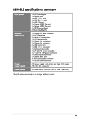
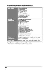
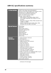
A8N-SLI specifications summary Rear panel Internal connectors Power requirement Form factor 1 x PS/2 mouse port 1 x Parallel port 1 x IEEE 1394a port 1 x LAN (RJ-45) port 4 x USB 2.0 ports 1 ... ports 1 x Floppy disk drive connector 2 x IDE connectors 4 x Serial ATA connectors 1 x CPU fan connector 2 x Chassis fan connectors 1 x Chipset fan connector 3 x USB connectors 1 x IEEE 1394a connector 1 x Serial port connector 1 x 24-pin ATX power connector 1 x 4-pin ATX 12V power connector 1 x Internal audio connector 1 x Optical drive audio 1x Front panel audio connector 1 x System panel connector...
A8N-SLI specifications summary Rear panel Internal connectors Power requirement Form factor 1 x PS/2 mouse port 1 x Parallel port 1 x IEEE 1394a port 1 x LAN (RJ-45) port 4 x USB 2.0 ports 1 ... ports 1 x Floppy disk drive connector 2 x IDE connectors 4 x Serial ATA connectors 1 x CPU fan connector 2 x Chassis fan connectors 1 x Chipset fan connector 3 x USB connectors 1 x IEEE 1394a connector 1 x Serial port connector 1 x 24-pin ATX power connector 1 x 4-pin ATX 12V power connector 1 x Internal audio connector 1 x Optical drive audio 1x Front panel audio connector 1 x System panel connector...
A8N-SLI English edition user's manual, version E2068
Page 22
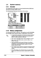
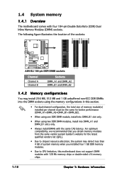
1.4 System memory 1.4.1 Overview The motherboard comes with the same CAS latency. The following figure illustrates the location of the sockets: DIMM_A1 DIMM_A2 DIMM_B1 DIMM_B2 A8N-SLI ® A8N-SLI 184-pin DDR DIMM sockets Channel Channel A Channel B Sockets DIMM_A1 and DIMM_A2 DIMM_B1 and DIMM_B2 1.4.2 Memory ... Modules (DIMM) sockets. For optimum compatibility, we recommended that you installed four 1 GB DDR memory modules. • Due to chipset resource allocation, the system may install 256 MB, 512 MB and 1 GB unbuffered non-ECC DDR DIMMs into the DIMM sockets using...
1.4 System memory 1.4.1 Overview The motherboard comes with the same CAS latency. The following figure illustrates the location of the sockets: DIMM_A1 DIMM_A2 DIMM_B1 DIMM_B2 A8N-SLI ® A8N-SLI 184-pin DDR DIMM sockets Channel Channel A Channel B Sockets DIMM_A1 and DIMM_A2 DIMM_B1 and DIMM_B2 1.4.2 Memory ... Modules (DIMM) sockets. For optimum compatibility, we recommended that you installed four 1 GB DDR memory modules. • Due to chipset resource allocation, the system may install 256 MB, 512 MB and 1 GB unbuffered non-ECC DDR DIMMs into the DIMM sockets using...

A8N-SLI English edition user's manual, version E2068
Page 32
... intend to create a Serial ATA RAID set to S A T A by the NVIDIA® nForce™4 SLI chipset, these connectors are set using these connectors. GND RSATA_RXN4 RSATA_RXP4 GND RSATA_TXN4 RSATA_TXP4 GND GND RSATA_RXN3 RSATA_RXP3 GND RSATA_TXN3 RSATA_TXP3 GND A8N-SLI ® A8N-SLI SATA connectors SATA4 SATA2 GND RSATA_RXN2 RSATA_RXP2 GND RSATA_TXN2 RSATA_TXP2 GND GND RSATA_RXN1 RSATA_RXP1...
... intend to create a Serial ATA RAID set to S A T A by the NVIDIA® nForce™4 SLI chipset, these connectors are set using these connectors. GND RSATA_RXN4 RSATA_RXP4 GND RSATA_TXN4 RSATA_TXP4 GND GND RSATA_RXN3 RSATA_RXP3 GND RSATA_TXN3 RSATA_TXP3 GND A8N-SLI ® A8N-SLI SATA connectors SATA4 SATA2 GND RSATA_RXN2 RSATA_RXP2 GND RSATA_TXN2 RSATA_TXP2 GND GND RSATA_RXN1 RSATA_RXP1...

A8N-SLI English edition user's manual, version E2068
Page 33
... the fan cables to the fan connector on the motherboard. GND +12V Rotation CPU_FAN CHA2_FAN CPU_FAN GND +12V Rotation A8N-SLI ® PWR_FAN CHIP_FAN CHA1_FAN A8N-SLI Fan connectors CHA2_FAN PWR_FAN CHIP_FAN GND +12V Rotation GND +12V Rotation CHA1_FAN GND +12V Rotation ASUS A8N-SLI 1-23 CPU, chassis, power, and chipset fan connectors (3-pin CPU_FAN, 3-pin CHA1_FAN, 3-pin CHA2_FAN...
... the fan cables to the fan connector on the motherboard. GND +12V Rotation CPU_FAN CHA2_FAN CPU_FAN GND +12V Rotation A8N-SLI ® PWR_FAN CHIP_FAN CHA1_FAN A8N-SLI Fan connectors CHA2_FAN PWR_FAN CHIP_FAN GND +12V Rotation GND +12V Rotation CHA1_FAN GND +12V Rotation ASUS A8N-SLI 1-23 CPU, chassis, power, and chipset fan connectors (3-pin CPU_FAN, 3-pin CHA1_FAN, 3-pin CHA2_FAN...
A8N-SLI English edition user's manual, version E2068
Page 54
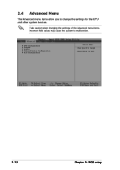
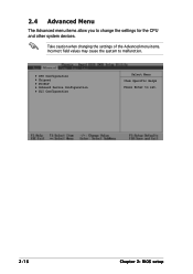
Take caution when changing the settings of the Advanced menu items. Incorrect field values may cause the system to change the settings for the CPU and other system devices. 2.4 Advanced Menu The Advanced menu items allow you to malfunction. CPU Configuration Chipset PCIPnP Onboard Device Configuration SLI Configuration Select Menu Item Specific Help Press Enter to set. 2-16 Chapter 2: BIOS setup
Take caution when changing the settings of the Advanced menu items. Incorrect field values may cause the system to change the settings for the CPU and other system devices. 2.4 Advanced Menu The Advanced menu items allow you to malfunction. CPU Configuration Chipset PCIPnP Onboard Device Configuration SLI Configuration Select Menu Item Specific Help Press Enter to set. 2-16 Chapter 2: BIOS setup

A8N-SLI English edition user's manual, version E2068
Page 56
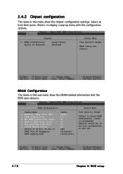
...configuration options. DRAM Configuration The items in this sub-menu show the chipset configuration settings. Select an item then press to set each configuration on your own. 2-18 Chapter 2: BIOS setup Chipset DRAM Configuration Errata 94 Enhanced [Press Enter] [Enabled] Select Menu Item... Specific Help DRAM timing and control. 2.4.2 Chipset configuration The items in this menu show the DRAM-related information that the ...
...configuration options. DRAM Configuration The items in this sub-menu show the chipset configuration settings. Select an item then press to set each configuration on your own. 2-18 Chapter 2: BIOS setup Chipset DRAM Configuration Errata 94 Enhanced [Press Enter] [Enabled] Select Menu Item... Specific Help DRAM timing and control. 2.4.2 Chipset configuration The items in this menu show the DRAM-related information that the ...
A8N-SLI English edition user's manual, version E2024
Page 4
... 2: BIOS setup 2.1 Managing and updating your BIOS 2-2 2.1.1 Creating a bootable floppy disk 2-2 2.1.2 AwardBIOS Flash Utility 2-3 2.1.3 ASUS CrashFree BIOS 2 utility 2-7 2.2 BIOS Setup program 2-8 2.2.1 BIOS menu bar 2-9 2.2.2 Legend bar 2-9 2.3 Main Menu 2-11...12 2.3.6 First, Second, Third, and Fourth SATA Master ..... 2-14 2.3.7 Installed Memory 2-15 2.4 Advanced Menu 2-16 2.4.1 CPU configuration 2-17 2.4.2 Chipset configuration 2-18 2.4.3 PCIPnP 2-20 2.4.4 Onboard device configuration 2-22 2.5 Power Menu 2-26 2.5.1 APM configuration 2-27 2.5.2 Hardware monitor 2-29 2.6 Boot...
... 2: BIOS setup 2.1 Managing and updating your BIOS 2-2 2.1.1 Creating a bootable floppy disk 2-2 2.1.2 AwardBIOS Flash Utility 2-3 2.1.3 ASUS CrashFree BIOS 2 utility 2-7 2.2 BIOS Setup program 2-8 2.2.1 BIOS menu bar 2-9 2.2.2 Legend bar 2-9 2.3 Main Menu 2-11...12 2.3.6 First, Second, Third, and Fourth SATA Master ..... 2-14 2.3.7 Installed Memory 2-15 2.4 Advanced Menu 2-16 2.4.1 CPU configuration 2-17 2.4.2 Chipset configuration 2-18 2.4.3 PCIPnP 2-20 2.4.4 Onboard device configuration 2-22 2.5 Power Menu 2-26 2.5.1 APM configuration 2-27 2.5.2 Hardware monitor 2-29 2.6 Boot...
A8N-SLI English edition user's manual, version E2024
Page 7
A8N-SLI specifications summary CPU Chipset Front Side Bus Memory Expansion slots Storage Audio LAN IEEE 1394 USB BIOS features Special features Socket 939 for AMD Athlon™ 64FX/AMD Athlon™ 64 processor Supports AMD 64 architecture that enables simultaneous 32-bit and 64-bit architecture NVIDIA® nForce™4 SLI 1 GHz (K8) / 800...
A8N-SLI specifications summary CPU Chipset Front Side Bus Memory Expansion slots Storage Audio LAN IEEE 1394 USB BIOS features Special features Socket 939 for AMD Athlon™ 64FX/AMD Athlon™ 64 processor Supports AMD 64 architecture that enables simultaneous 32-bit and 64-bit architecture NVIDIA® nForce™4 SLI 1 GHz (K8) / 800...
A8N-SLI English edition user's manual, version E2024
Page 8
A8N-SLI specifications summary Rear panel Internal connectors Power requirement Form factor 1 x PS/2 mouse port 1 x Parallel port 1 x IEEE 1394a port 1 x LAN (RJ-45) port 4 x USB 2.0 ports 1 ... ports 1 x Floppy disk drive connector 2 x IDE connectors 4 x Serial ATA connectors 1 x CPU fan connector 2 x Chassis fan connectors 1 x Chipset fan connector 3 x USB connectors 1 x IEEE 1394a connector 1 x Serial port connector 1 x 24-pin ATX power connector 1 x 4-pin ATX 12V power connector 1 x Internal audio connector 1 x Optical drive audio 1x Front panel audio connector 1 x System panel connector...
A8N-SLI specifications summary Rear panel Internal connectors Power requirement Form factor 1 x PS/2 mouse port 1 x Parallel port 1 x IEEE 1394a port 1 x LAN (RJ-45) port 4 x USB 2.0 ports 1 ... ports 1 x Floppy disk drive connector 2 x IDE connectors 4 x Serial ATA connectors 1 x CPU fan connector 2 x Chassis fan connectors 1 x Chipset fan connector 3 x USB connectors 1 x IEEE 1394a connector 1 x Serial port connector 1 x 24-pin ATX power connector 1 x 4-pin ATX 12V power connector 1 x Internal audio connector 1 x Optical drive audio 1x Front panel audio connector 1 x System panel connector...
A8N-SLI English edition user's manual, version E2024
Page 20
...A8N-SLI ® A8N-SLI 184-pin DDR DIMM sockets Channel Channel A Channel B Sockets DIMM_A1 and DIMM_A2 DIMM_B1 and DIMM_B2 1.4.2 Memory configurations You may detect less than 4 GB of system memory when you obtain memory modules from the same vendor system builder's website for the latest qualified vendors list (QVL). • Due to chipset...into DIMM_A1 and DIMM_B1 slots only. • Always install DIMMs with the same CAS latency. 1.4 System memory 1.4.1 Overview The motherboard comes with 128 Mb memory chips or double-sided x16 memory chips. 1-12 Chapter 1: Hardware information
...A8N-SLI ® A8N-SLI 184-pin DDR DIMM sockets Channel Channel A Channel B Sockets DIMM_A1 and DIMM_A2 DIMM_B1 and DIMM_B2 1.4.2 Memory configurations You may detect less than 4 GB of system memory when you obtain memory modules from the same vendor system builder's website for the latest qualified vendors list (QVL). • Due to chipset...into DIMM_A1 and DIMM_B1 slots only. • Always install DIMMs with the same CAS latency. 1.4 System memory 1.4.1 Overview The motherboard comes with 128 Mb memory chips or double-sided x16 memory chips. 1-12 Chapter 1: Hardware information
A8N-SLI English edition user's manual, version E2024
Page 30
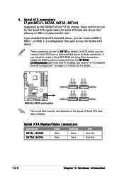
...for details. GND RSATA_RXN4 RSATA_RXP4 GND RSATA_TXN4 RSATA_TXP4 GND GND RSATA_RXN3 RSATA_RXP3 GND RSATA_TXN3 RSATA_TXP3 GND A8N-SLI ® A8N-SLI SATA connectors SATA4 SATA2 GND RSATA_RXN2 RSATA_RXP2 GND RSATA_TXN2 RSATA_TXP2 GND GND RSATA_RXN1 RSATA_RXP1 GND RSATA_TXN1 ...Serial ATA hard disk drives, you can create a RAID 0, RAID 1, or RAID 1+0 configuration that allow up to S A T A by the NVIDIA® nForce™4 SLI chipset, these connectors are set using these connectors. See section "2.4.3 Onboard Devices Configuration" on the speed of each port from the N V R A I D C o n ...
...for details. GND RSATA_RXN4 RSATA_RXP4 GND RSATA_TXN4 RSATA_TXP4 GND GND RSATA_RXN3 RSATA_RXP3 GND RSATA_TXN3 RSATA_TXP3 GND A8N-SLI ® A8N-SLI SATA connectors SATA4 SATA2 GND RSATA_RXN2 RSATA_RXP2 GND RSATA_TXN2 RSATA_TXP2 GND GND RSATA_RXN1 RSATA_RXP1 GND RSATA_TXN1 ...Serial ATA hard disk drives, you can create a RAID 0, RAID 1, or RAID 1+0 configuration that allow up to S A T A by the NVIDIA® nForce™4 SLI chipset, these connectors are set using these connectors. See section "2.4.3 Onboard Devices Configuration" on the speed of each port from the N V R A I D C o n ...
A8N-SLI English edition user's manual, version E2024
Page 31
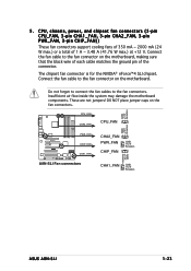
... damage the motherboard components. GND +12V Rotation CPU_FAN CHA2_FAN CPU_FAN GND +12V Rotation A8N-SLI ® PWR_FAN CHIP_FAN CHA1_FAN A8N-SLI Fan connectors CHA2_FAN PWR_FAN CHIP_FAN GND +12V Rotation GND +12V Rotation CHA1_FAN GND +12V Rotation ASUS A8N-SLI 1-23 These... are not jumpers! DO NOT place jumper caps on the motherboard, making sure that the black wire of each cable matches the ground pin of 1 A ~ 3.48 A (41.76 W max.) at +12 V. Do not forget to connect the fan cables to the fan connector on the motherboard. 5 . The chipset...
... damage the motherboard components. GND +12V Rotation CPU_FAN CHA2_FAN CPU_FAN GND +12V Rotation A8N-SLI ® PWR_FAN CHIP_FAN CHA1_FAN A8N-SLI Fan connectors CHA2_FAN PWR_FAN CHIP_FAN GND +12V Rotation GND +12V Rotation CHA1_FAN GND +12V Rotation ASUS A8N-SLI 1-23 These... are not jumpers! DO NOT place jumper caps on the motherboard, making sure that the black wire of each cable matches the ground pin of 1 A ~ 3.48 A (41.76 W max.) at +12 V. Do not forget to connect the fan cables to the fan connector on the motherboard. 5 . The chipset...
A8N-SLI English edition user's manual, version E2024
Page 52
2.4 Advanced Menu The Advanced menu items allow you to set. 2-16 Chapter 2: BIOS setup CPU Configuration Chipset PCIPnP Onboard Device Configuration SLI Configuration Select Menu Item Specific Help Press Enter to change the settings for the CPU and other system devices. Take caution when changing the settings of the Advanced menu items. Incorrect field values may cause the system to malfunction.
2.4 Advanced Menu The Advanced menu items allow you to set. 2-16 Chapter 2: BIOS setup CPU Configuration Chipset PCIPnP Onboard Device Configuration SLI Configuration Select Menu Item Specific Help Press Enter to change the settings for the CPU and other system devices. Take caution when changing the settings of the Advanced menu items. Incorrect field values may cause the system to malfunction.
A8N-SLI English edition user's manual, version E2024
Page 54
... Errata 94 Enhanced [Press Enter] [Enabled] Select Menu Item Specific Help DRAM timing and control. DRAM Configuration The items in this sub-menu show the chipset configuration settings. DRAM Configuration Timing Mode x Memclock index value (Mhz) x CAS# Latency (Tcl) x Min RAS# active time (Tras) x RAS# to CAS# delay (Trcd) ... pop-up menu with the configuration options. Select an item then press to set each configuration on your own. 2-18 Chapter 2: BIOS setup 2.4.2 Chipset configuration The items in this menu show the DRAM-related information that the BIOS auto-detects.
... Errata 94 Enhanced [Press Enter] [Enabled] Select Menu Item Specific Help DRAM timing and control. DRAM Configuration The items in this sub-menu show the chipset configuration settings. DRAM Configuration Timing Mode x Memclock index value (Mhz) x CAS# Latency (Tcl) x Min RAS# active time (Tras) x RAS# to CAS# delay (Trcd) ... pop-up menu with the configuration options. Select an item then press to set each configuration on your own. 2-18 Chapter 2: BIOS setup 2.4.2 Chipset configuration The items in this menu show the DRAM-related information that the BIOS auto-detects.
A8N-SLI English edition user's manual, version E1947
Page 11
...A8N-SLI specifications summary CPU Socket 939 for dual PCI Express graphics cards ASUS Two-slot thermal design Storage NVIDIA® nForce™ 4 SLI chipset supports: - 2 x Ultra DMA 133/100/66/33 - 4 x Serial ATA 3Gb/s drives - Technology Chipset NVIDIA® nForce™ 4 SLI Supports NVIDIA® Scalable Link Interface™ (SLI...that spans across the Serial ATA and Parallel ATA drives (continued on second slot (black) ASUS EZ Selector ASUS EZ Plug™ ASUS SLI Warning LED ASUS PEG Link for AMD Athlon™ 64FX/AMD Athlon™ 64 processor Supports AMD 64 architecture...
...A8N-SLI specifications summary CPU Socket 939 for dual PCI Express graphics cards ASUS Two-slot thermal design Storage NVIDIA® nForce™ 4 SLI chipset supports: - 2 x Ultra DMA 133/100/66/33 - 4 x Serial ATA 3Gb/s drives - Technology Chipset NVIDIA® nForce™ 4 SLI Supports NVIDIA® Scalable Link Interface™ (SLI...that spans across the Serial ATA and Parallel ATA drives (continued on second slot (black) ASUS EZ Selector ASUS EZ Plug™ ASUS SLI Warning LED ASUS PEG Link for AMD Athlon™ 64FX/AMD Athlon™ 64 processor Supports AMD 64 architecture...
A8N-SLI English edition user's manual, version E1947
Page 12
... ASUS EZFlash ASUS Q-Fan ASUS CrashFree BIOS 2 ASUS Multi-language BIOS ASUS MyLogo2 ASUS Instant Music ASUS EZ Selector ASUS SLI Warning LED ASUS EZ Plug 1 x Floppy disk drive connector 2 x IDE connectors 4 x Serial ATA connectors 1 x ASUS EZ selector card connector 1 x CPU fan connector 1 x Power fan connector 2 x Chassis fan connector 1 x Chipset fan connector 1 x Serial port connector (COM port) 1 x 24-pin ATX power connector 1 x 4-pin ATX...
... ASUS EZFlash ASUS Q-Fan ASUS CrashFree BIOS 2 ASUS Multi-language BIOS ASUS MyLogo2 ASUS Instant Music ASUS EZ Selector ASUS SLI Warning LED ASUS EZ Plug 1 x Floppy disk drive connector 2 x IDE connectors 4 x Serial ATA connectors 1 x ASUS EZ selector card connector 1 x CPU fan connector 1 x Power fan connector 2 x Chassis fan connector 1 x Chipset fan connector 1 x Serial port connector (COM port) 1 x 24-pin ATX power connector 1 x 4-pin ATX...
A8N-SLI English edition user's manual, version E1947
Page 18
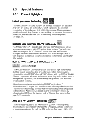
...NVIDIA® ActiveArmor™ (NV ActiveArmor™) engine that provides advanced data packet inspection. AMD Cool 'n' Quiet!™ Technology The motherboard supports the AMD Cool 'n' Quiet!™ Technology that only safe data packets are based on AMD's 64-bit and 32-bit ...provide a dramatic leap forward in a single system. See Chapter 6 for details. Integrated into the NVIDIA® nForce4® SLI™ chipset with the NVIDIA® Gigabit Ethernet, it boosts overall system performance by offloading the CPU from intruders. Additionally, it provides advanced ...
...NVIDIA® ActiveArmor™ (NV ActiveArmor™) engine that provides advanced data packet inspection. AMD Cool 'n' Quiet!™ Technology The motherboard supports the AMD Cool 'n' Quiet!™ Technology that only safe data packets are based on AMD's 64-bit and 32-bit ...provide a dramatic leap forward in a single system. See Chapter 6 for details. Integrated into the NVIDIA® nForce4® SLI™ chipset with the NVIDIA® Gigabit Ethernet, it boosts overall system performance by offloading the CPU from intruders. Additionally, it provides advanced ...
A8N-SLI English edition user's manual, version E1947
Page 19
...; interface The motherboard fully supports PCI Express, the latest I/O interconnect technology that speeds up to 4GB of new features including Native Command Queuing (NCQ), Power Management (PM) Implementation Algorithm, and Hot Swap. See page 2-17 for details. ASUS A8N-SLI 1-3 PCI Express...PDIF digital sound ready The motherboard supports the S/PDIF Out function through the Serial ATA interfaces and the NVIDIA® SLI™ chipset. See page 2-11. RAID solution The NVIDIA® nForce™ 4 SLI™ RAID controller onboard provides the motherboard with lower pin count, and...
...; interface The motherboard fully supports PCI Express, the latest I/O interconnect technology that speeds up to 4GB of new features including Native Command Queuing (NCQ), Power Management (PM) Implementation Algorithm, and Hot Swap. See page 2-17 for details. ASUS A8N-SLI 1-3 PCI Express...PDIF digital sound ready The motherboard supports the S/PDIF Out function through the Serial ATA interfaces and the NVIDIA® SLI™ chipset. See page 2-11. RAID solution The NVIDIA® nForce™ 4 SLI™ RAID controller onboard provides the motherboard with lower pin count, and...

