
A7V8X-X User Manual
Page 11
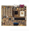
Motherboard Info ASUS A7V8X-X Motherboard 1-1 Chapter 1 This chapter gives information about the ASUS A7V8X-X motherboard that came with the system.This chapter includes the motherboard layout, jumper settings, and connector locations.
Motherboard Info ASUS A7V8X-X Motherboard 1-1 Chapter 1 This chapter gives information about the ASUS A7V8X-X motherboard that came with the system.This chapter includes the motherboard layout, jumper settings, and connector locations.
A7V8X-X User Manual
Page 12
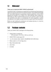
...30.5 cm x 24.5 cm) ASUS A7V8X-X series support CD 1 pc. 80-conductor ribbon cable for UltraDMA/66/100/133 IDE drives Ribbon cable for socket A processors. Unique ASUS features such as ASUS C.O.P., ASUS C.P.R., ASUS EZFlash, ASUS JumperFree, ASUS MyLogo, ASUS CrashFree BIOS and more are included ...the motherboard. Before you for guaranteed consumer satisfaction. The ASUS A7V8X-X motherboard is loaded with the list below. 1.2 Package contents Check your package with value-added features for buying the ASUS® A7V8X-X motherboard! Thank you start installing the motherboard, and hardware...
...30.5 cm x 24.5 cm) ASUS A7V8X-X series support CD 1 pc. 80-conductor ribbon cable for UltraDMA/66/100/133 IDE drives Ribbon cable for socket A processors. Unique ASUS features such as ASUS C.O.P., ASUS C.P.R., ASUS EZFlash, ASUS JumperFree, ASUS MyLogo, ASUS CrashFree BIOS and more are included ...the motherboard. Before you for guaranteed consumer satisfaction. The ASUS A7V8X-X motherboard is loaded with the list below. 1.2 Package contents Check your package with value-added features for buying the ASUS® A7V8X-X motherboard! Thank you start installing the motherboard, and hardware...

A7V8X-X User Manual
Page 13
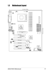
Refer to facilitate the installation and future upgrades. 1.3 Motherboard components Before you install the motherboard, learn about its major components and available features to the succeeding pages for the component descriptions. 1 2 3 4 14 13 12 11 15 10 9 16 17 25 24 23 ASUS A7V8X-X Motherboard 22 21 5 6 7 8 18 19 20 1-3
Refer to facilitate the installation and future upgrades. 1.3 Motherboard components Before you install the motherboard, learn about its major components and available features to the succeeding pages for the component descriptions. 1 2 3 4 14 13 12 11 15 10 9 16 17 25 24 23 ASUS A7V8X-X Motherboard 22 21 5 6 7 8 18 19 20 1-3

A7V8X-X User Manual
Page 15
... this jack becomes Rear Speaker Out. (on audio models only) The functions of this jack becomes Bass/ Center. (on LAN model only) 14 AGP slot. ASUS A7V8X-X Motherboard 1-5 This Line Out (lime) jack connects a headphone or a speaker. This Accelerated Graphics Port (AGP) slot supports 1.5V AGP8X mode graphics cards for 5.1 surround sound...
... this jack becomes Rear Speaker Out. (on audio models only) The functions of this jack becomes Bass/ Center. (on LAN model only) 14 AGP slot. ASUS A7V8X-X Motherboard 1-5 This Line Out (lime) jack connects a headphone or a speaker. This Accelerated Graphics Port (AGP) slot supports 1.5V AGP8X mode graphics cards for 5.1 surround sound...
A7V8X-X User Manual
Page 17
...:Line Out Below:Mic In AUX CD LAN PHY FP_AUDIO Audio Codec MDC VIA KT400 Chipset Accelerated Graphics Port (AGP) 01 23 45 PCI Slot 1 A7V8X-X PCI Slot 2 PCI Slot 3 PCI Slot 4 PCI Slot 5 ® PCI Slot 6 VIA VT8235 Chipset CR2032 3V Lithium Cell CMOS Power CLRTC Super I/O GAME USBPW56 USB56...
...:Line Out Below:Mic In AUX CD LAN PHY FP_AUDIO Audio Codec MDC VIA KT400 Chipset Accelerated Graphics Port (AGP) 01 23 45 PCI Slot 1 A7V8X-X PCI Slot 2 PCI Slot 3 PCI Slot 4 PCI Slot 5 ® PCI Slot 6 VIA VT8235 Chipset CR2032 3V Lithium Cell CMOS Power CLRTC Super I/O GAME USBPW56 USB56...

A7V8X-X User Manual
Page 19
... the holes indicated by circles to secure the motherboard to do so may damage the motherboard. Place this side towards the rear of the chassis ASUS A7V8X-X Motherboard 1-9 Make sure to ensure that measures 12 inches x 9.6 inches (30.5 cm x 24.5 cm). 1.7 Motherboard installation Before you place it . The motherboard uses the ATX...
... the holes indicated by circles to secure the motherboard to do so may damage the motherboard. Place this side towards the rear of the chassis ASUS A7V8X-X Motherboard 1-9 Make sure to ensure that measures 12 inches x 9.6 inches (30.5 cm x 24.5 cm). 1.7 Motherboard installation Before you place it . The motherboard uses the ATX...
A7V8X-X User Manual
Page 21
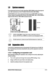
...DIMM. Refer to avoid damaging the DIMM. Also, a DDR DIMM is single notched while an SDR DIMM is double notched. 104 Pins A7V8X-X ® 80 Pins A7V8X-X 184-Pin DDR DIMM Sockets A DDR or SDR DIMM is keyed with a notch so that it has a 184-pin footprint compared to...to 2 banks only and PC2700 maximum to the card. Assign an IRQ to 4 banks only. 1.10 Expansion slots The A7V8X-X motherboard has six (6) expansion PCI slots and one direction. ASUS A7V8X-X Motherboard 1-11 Install the software drivers for the expansion card. 1.9 System memory The motherboard has three Double Data Rate (...
...DIMM. Refer to avoid damaging the DIMM. Also, a DDR DIMM is single notched while an SDR DIMM is double notched. 104 Pins A7V8X-X ® 80 Pins A7V8X-X 184-Pin DDR DIMM Sockets A DDR or SDR DIMM is keyed with a notch so that it has a 184-pin footprint compared to...to 2 banks only and PC2700 maximum to the card. Assign an IRQ to 4 banks only. 1.10 Expansion slots The A7V8X-X motherboard has six (6) expansion PCI slots and one direction. ASUS A7V8X-X Motherboard 1-11 Install the software drivers for the expansion card. 1.9 System memory The motherboard has three Double Data Rate (...

A7V8X-X User Manual
Page 23
Both jumpers are for the internal USB header that you keep the default setting (Disable). ASUS A7V8X-X Motherboard 1-13 Set to +5VSB to wake up the computer from S3 sleep mode (no power to the CPU. Or, the system does ...5VSB) whether under normal condition or in reduced power mode). USBPW12 USBPW34 12 23 A7V8X-X ® +5V (Default) +5VSB USBPW56 12 23 A7V8X-X USB Device Wake Up +5V (Default) +5VSB 2. OVER_VOLT 12 23 Enable Disable (Default) A7V8X-X ® A7V8X-X OVER_VOLT Setting Setting to a very high core voltage may adjust the CPU VCORE ...
Both jumpers are for the internal USB header that you keep the default setting (Disable). ASUS A7V8X-X Motherboard 1-13 Set to +5VSB to wake up the computer from S3 sleep mode (no power to the CPU. Or, the system does ...5VSB) whether under normal condition or in reduced power mode). USBPW12 USBPW34 12 23 A7V8X-X ® +5V (Default) +5VSB USBPW56 12 23 A7V8X-X USB Device Wake Up +5V (Default) +5VSB 2. OVER_VOLT 12 23 Enable Disable (Default) A7V8X-X ® A7V8X-X OVER_VOLT Setting Setting to a very high core voltage may adjust the CPU VCORE ...

A7V8X-X User Manual
Page 25
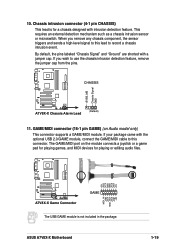
USB headers (10-1 pin USB56) If the USB 2.0 port connectors on the motherboard. 1. USB+6V USB_P6USB_P6+ GND NC A7V8X-X ® USB56 1 USB+5V USB_P5USB_P5+ GND A7V8X-X USB 2.0 Header The USB/GAME module is 230W, or 300W for four additional USB port connectors. 1.12 Connectors This section... power connectors (20-pin ATXPWR) These connectors connect to replace the power supply in the package. ATXPWR A7V8X-X ® +3.3VDC -12.0VDC COM PS_ON# COM COM COM -5.0VDC +5.0VDC +5.0VDC A7V8X-X ATX Power Connectors +3.3VDC +3.3VDC COM +5.0VDC COM +5.0VDC COM PWR_OK +5VSB +12.0VDC If you...
USB headers (10-1 pin USB56) If the USB 2.0 port connectors on the motherboard. 1. USB+6V USB_P6USB_P6+ GND NC A7V8X-X ® USB56 1 USB+5V USB_P5USB_P5+ GND A7V8X-X USB 2.0 Header The USB/GAME module is 230W, or 300W for four additional USB port connectors. 1.12 Connectors This section... power connectors (20-pin ATXPWR) These connectors connect to replace the power supply in the package. ATXPWR A7V8X-X ® +3.3VDC -12.0VDC COM PS_ON# COM COM COM -5.0VDC +5.0VDC +5.0VDC A7V8X-X ATX Power Connectors +3.3VDC +3.3VDC COM +5.0VDC COM +5.0VDC COM PWR_OK +5VSB +12.0VDC If you...

A7V8X-X User Manual
Page 27
...) or a total of sufficient air flow within the system may vary depending on the fan connectors! CPU_FAN GND +12V Rotation A7V8X-X ® CHA_FAN Rotation +12V GND A7V8X-X 12-Volt Cooling Fan Power Do not forget to connect the fan cables to the ground pin. Lack of 1A (12W... ® NOTE: Orient the red markings on the floppy ribbon cable to prevent incorrect insertion when using ribbon cables with pin 5 plug). ASUS A7V8X-X Motherboard 1-17 A7V8X-X Floppy Disk Drive Connector 6. After connecting one end to the motherboard, connect the other end to the floppy drive. (Pin 5 is ...
...) or a total of sufficient air flow within the system may vary depending on the fan connectors! CPU_FAN GND +12V Rotation A7V8X-X ® CHA_FAN Rotation +12V GND A7V8X-X 12-Volt Cooling Fan Power Do not forget to connect the fan cables to the ground pin. Lack of 1A (12W... ® NOTE: Orient the red markings on the floppy ribbon cable to prevent incorrect insertion when using ribbon cables with pin 5 plug). ASUS A7V8X-X Motherboard 1-17 A7V8X-X Floppy Disk Drive Connector 6. After connecting one end to the motherboard, connect the other end to the floppy drive. (Pin 5 is ...
A7V8X-X User Manual
Page 29
CHASSIS +5VSB_MB Chassis Signal GND A7V8X-X ® A7V8X-X Chassis Alarm Lead (Default) 11. ASUS A7V8X-X Motherboard MIDI_IN J2B2 J2CY MIDI_OUT J2CX J2B1 +5V 1-19 By default, the pins labeled "Chassis Signal" and "Ground" are shorted with intrusion detection feature.... microswitch. Chassis intrusion connector (4-1 pin CHASSIS) This lead is for playing or editing audio files. +5V J1B2 J1CY GND GND J1CX J1B1 +5V A7V8X-X ® A7V8X-X Game Connector GAME The USB/GAME module is not included in the package. If you remove any chassis component, the sensor triggers and sends a...
CHASSIS +5VSB_MB Chassis Signal GND A7V8X-X ® A7V8X-X Chassis Alarm Lead (Default) 11. ASUS A7V8X-X Motherboard MIDI_IN J2B2 J2CY MIDI_OUT J2CX J2B1 +5V 1-19 By default, the pins labeled "Chassis Signal" and "Ground" are shorted with intrusion detection feature.... microswitch. Chassis intrusion connector (4-1 pin CHASSIS) This lead is for playing or editing audio files. +5V J1B2 J1CY GND GND J1CX J1B1 +5V A7V8X-X ® A7V8X-X Game Connector GAME The USB/GAME module is not included in the package. If you remove any chassis component, the sensor triggers and sends a...
A7V8X-X User Manual
Page 31
Chapter 2 This chapter gives information about the ASUS A7V8X-X Binary Input/Output System (BIOS).This chapter includes updating the BIOS using the ASUS AFLASH BIOS that is bundled with the support CD. BIOS Information ASUS A7V8X-X Motherboard 2-1
Chapter 2 This chapter gives information about the ASUS A7V8X-X Binary Input/Output System (BIOS).This chapter includes updating the BIOS using the ASUS AFLASH BIOS that is bundled with the support CD. BIOS Information ASUS A7V8X-X Motherboard 2-1
A7V8X-X User Manual
Page 32
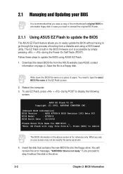
... so it is built-in the drive. 2-2 Chapter 2: BIOS Information ASUS EZ Flash V1.00 Copyright (C) 2002, ASUSTeK COMPUTER INC. [Onboard BIOS Information] BIOS Version : ASUS A7V8X-X BIOS Revision 1001 Beta 003 BIOS Model : A7V8X-X BIOS Built Date : 12/14/02 Please Enter File Name for ...reference only. You will copy file from a diskette and using ASUS EZ Flash. 1. Follow these steps to a floppy disk...
... so it is built-in the drive. 2-2 Chapter 2: BIOS Information ASUS EZ Flash V1.00 Copyright (C) 2002, ASUSTeK COMPUTER INC. [Onboard BIOS Information] BIOS Version : ASUS A7V8X-X BIOS Revision 1001 Beta 003 BIOS Model : A7V8X-X BIOS Built Date : 12/14/02 Please Enter File Name for ...reference only. You will copy file from a diskette and using ASUS EZ Flash. 1. Follow these steps to a floppy disk...
A7V8X-X User Manual
Page 33
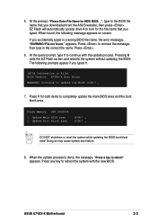
... process. Doing so may cause system boot failure. 8. Press any key to continue with the new BIOS. ASUS A7V8X-X Motherboard 2-3 EZ Flash will automatically access drive A to remove the message, then type in File] BIOS Version: A7V8X-X Boot Block WARNING! File not found , the following prompts appear if you typed Y. [BIOS Information in...
... process. Doing so may cause system boot failure. 8. Press any key to continue with the new BIOS. ASUS A7V8X-X Motherboard 2-3 EZ Flash will automatically access drive A to remove the message, then type in File] BIOS Version: A7V8X-X Boot Block WARNING! File not found , the following prompts appear if you typed Y. [BIOS Information in...
A7V8X-X User Manual
Page 35
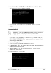
Boot from the Main menu and press . The Update BIOS Including Boot Block and ESCD screen appears. 5. ASUS A7V8X-X Motherboard 2-5 Save Current BIOS to more problems with the motherboard! 1. Type a filename and the path, for example, A:\XXX- At the "A:\" prompt, type AFLASH and then ... File from the floppy disk. 3. The Save Current BIOS To File screen appears. 6. XX.XXX, then press . 5. Download an updated ASUS BIOS file from the Internet (WWW or FTP) (see ASUS CONTACT INFORMATION on page x for details) and save to the boot floppy disk you are sure that the new BIOS revision...
Boot from the Main menu and press . The Update BIOS Including Boot Block and ESCD screen appears. 5. ASUS A7V8X-X Motherboard 2-5 Save Current BIOS to more problems with the motherboard! 1. Type a filename and the path, for example, A:\XXX- At the "A:\" prompt, type AFLASH and then ... File from the floppy disk. 3. The Save Current BIOS To File screen appears. 6. XX.XXX, then press . 5. Download an updated ASUS BIOS file from the Internet (WWW or FTP) (see ASUS CONTACT INFORMATION on page x for details) and save to the boot floppy disk you are sure that the new BIOS revision...
A7V8X-X User Manual
Page 37
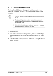
Follow the BIOS update procedure in case the original BIOS fails or gets corrupted. 1. ASUS A7V8X-X Motherboard 2-7 To update the BIOS: 1. 2.1.3 CrashFree BIOS feature The CrashFree BIOS feature allows you created following the procedure in section 2.1.2, and should contain the AFLASH....
Follow the BIOS update procedure in case the original BIOS fails or gets corrupted. 1. ASUS A7V8X-X Motherboard 2-7 To update the BIOS: 1. 2.1.3 CrashFree BIOS feature The CrashFree BIOS feature allows you created following the procedure in section 2.1.2, and should contain the AFLASH....
A7V8X-X User Manual
Page 39
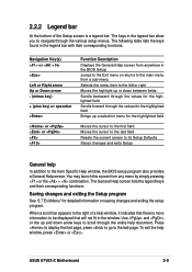
... Help screen from anywhere in the BIOS Setup Jumps to the Exit menu or returns to be displayed that will not fit in the window. ASUS A7V8X-X Motherboard 2-9 When a scroll bar appears to the right of the Setup screen is more information to the main menu from any menu by simply pressing...
... Help screen from anywhere in the BIOS Setup Jumps to the Exit menu or returns to be displayed that will not fit in the window. ASUS A7V8X-X Motherboard 2-9 When a scroll bar appears to the right of the Setup screen is more information to the main menu from any menu by simply pressing...
A7V8X-X User Manual
Page 41
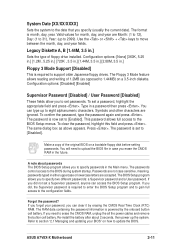
... the CMOS Real Time Clock (RTC) RAM. The RAM data containing the password information is set a Supervisor password, anyone can access the BIOS Setup program. ASUS A7V8X-X Motherboard 2-11 This password allows full access to [Disabled]. The same dialog box as opposed to the configuration fields. You will need to specify two...
... the CMOS Real Time Clock (RTC) RAM. The RAM data containing the password information is set a Supervisor password, anyone can access the BIOS Setup program. ASUS A7V8X-X Motherboard 2-11 This password allows full access to [Disabled]. The same dialog box as opposed to the configuration fields. You will need to specify two...

A7V8X-X User Manual
Page 43
... Translation Method field to [Manual]. If no drive is used without regard for cylinders, heads, or sectors. Sector This field configures the number of cylinders. ASUS A7V8X-X Motherboard 2-13 Other options for ZIP-compatible disk drives [MO] - for IDE devices not listed here After making your selections on the drive information you...
... Translation Method field to [Manual]. If no drive is used without regard for cylinders, heads, or sectors. Sector This field configures the number of cylinders. ASUS A7V8X-X Motherboard 2-13 Other options for ZIP-compatible disk drives [MO] - for IDE devices not listed here After making your selections on the drive information you...

A7V8X-X User Manual
Page 45
... speed) and external frequency. Configuration options: [Auto] [200] [266] [333] [400]. The bus frequency (external frequency) multiplied by the bus multiple equals the CPU speed. ASUS A7V8X-X Motherboard 2-15 Configuration options: [1/4 Sec] [1/2 Sec] [3/4 Sec] [1 Sec] 2.4 Advanced Menu CPU Speed This displays the current speed of the CPU installed. CPU VCore Setting [Auto...
... speed) and external frequency. Configuration options: [Auto] [200] [266] [333] [400]. The bus frequency (external frequency) multiplied by the bus multiple equals the CPU speed. ASUS A7V8X-X Motherboard 2-15 Configuration options: [1/4 Sec] [1/2 Sec] [3/4 Sec] [1 Sec] 2.4 Advanced Menu CPU Speed This displays the current speed of the CPU installed. CPU VCore Setting [Auto...


