
Motherboard DIY Troubleshooting Guide
Page 10
A7V8X-X: les spécifications (suite) BIOS Standard industriel Gestion Format CD de support Accessoires 2Mb Flash ROM, Award BIOS, DMI2.0, PnP, WfM2.0, SM BIOS 2.3, TCAV, EZ Flash, ASUS MyLogo, ASUS CrashFree BIOS, ASUS JumperFree, ASUS C.P.R. PCI 2.2, USB 2.0 WfM2.0, DMI2.0, WOR, WOL, Chassis Intrusion ATX: 30.5 cm x 24.5 cm Pilotes ASUS PC Probe Trend Microtm PC-cillin 2002 ASUS LiveUpdate Manuel CD de support 1 câble UltraDMA 133/100/66 Câble FDD I/O shield * Les spécifications peuvent changer sans préavis. x
A7V8X-X: les spécifications (suite) BIOS Standard industriel Gestion Format CD de support Accessoires 2Mb Flash ROM, Award BIOS, DMI2.0, PnP, WfM2.0, SM BIOS 2.3, TCAV, EZ Flash, ASUS MyLogo, ASUS CrashFree BIOS, ASUS JumperFree, ASUS C.P.R. PCI 2.2, USB 2.0 WfM2.0, DMI2.0, WOR, WOL, Chassis Intrusion ATX: 30.5 cm x 24.5 cm Pilotes ASUS PC Probe Trend Microtm PC-cillin 2002 ASUS LiveUpdate Manuel CD de support 1 câble UltraDMA 133/100/66 Câble FDD I/O shield * Les spécifications peuvent changer sans préavis. x
A7V8X-X User Manual
Page 3
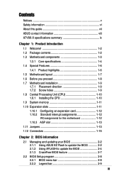
Features Contents Notices v Safety information vi About this guide vii ASUS contact information viii A7V8X-X specifications summary ix Chapter 1: Product introduction 1.1 Welcome 1-2 1.2 Package contents 1-2 1.3 Motherboard components 1-3 1.3.1 Core specifications 1-4 1.4 ... 1.11 Jumpers 1-13 1.12 Connectors 1-15 Chapter 2: BIOS information 2.1 Managing and updating your BIOS 2-2 2.1.1 Using ASUS EZ Flash to update the BIOS 2-2 2.1.2 Using AFLASH to update the BIOS 2-4 2.1.3 CrashFree BIOS feature 2-7 2.2 BIOS Setup program 2-8 2.2.1 BIOS menu bar 2-8 2.2.2 Legend bar 2-9 iii
Features Contents Notices v Safety information vi About this guide vii ASUS contact information viii A7V8X-X specifications summary ix Chapter 1: Product introduction 1.1 Welcome 1-2 1.2 Package contents 1-2 1.3 Motherboard components 1-3 1.3.1 Core specifications 1-4 1.4 ... 1.11 Jumpers 1-13 1.12 Connectors 1-15 Chapter 2: BIOS information 2.1 Managing and updating your BIOS 2-2 2.1.1 Using ASUS EZ Flash to update the BIOS 2-2 2.1.2 Using AFLASH to update the BIOS 2-4 2.1.3 CrashFree BIOS feature 2-7 2.2 BIOS Setup program 2-8 2.2.1 BIOS menu bar 2-8 2.2.2 Legend bar 2-9 iii
A7V8X-X User Manual
Page 9
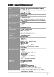
A7V8X-X specifications summary CPU Chipset Front Side Bus (FSB) Memory Expansion slots IDE Audio (optional) LAN (optional) USB 2.0 Special Features Back Panel I/O Ports Internal I /O ... CODEC S/PDIF out interface Realtek 10/100 Mbps Ethernet PHY VT8235 built-in USB 2.0 6 x USB 2.0 ports ASUS MyLogo ASUS EZ Flash ASUS C.P.R. (CPU Parameter Recall) Power Loss Restart ASUS Jumperfree SFS (Stepless Frequency Selection) ASUS C.O.P. (CPU Overheating Protection) CrashFree BIOS 1 x Parallel 1 x Serial 1 x S/PDIF out (on audio model only) 1 x PS/2 Keyboard 1 x PS/2 Mouse 1 x Audio I /O Connectors ...
A7V8X-X specifications summary CPU Chipset Front Side Bus (FSB) Memory Expansion slots IDE Audio (optional) LAN (optional) USB 2.0 Special Features Back Panel I/O Ports Internal I /O ... CODEC S/PDIF out interface Realtek 10/100 Mbps Ethernet PHY VT8235 built-in USB 2.0 6 x USB 2.0 ports ASUS MyLogo ASUS EZ Flash ASUS C.P.R. (CPU Parameter Recall) Power Loss Restart ASUS Jumperfree SFS (Stepless Frequency Selection) ASUS C.O.P. (CPU Overheating Protection) CrashFree BIOS 1 x Parallel 1 x Serial 1 x S/PDIF out (on audio model only) 1 x PS/2 Keyboard 1 x PS/2 Mouse 1 x Audio I /O Connectors ...

A7V8X-X User Manual
Page 10
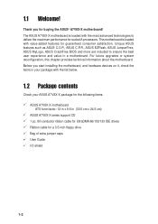
x A7V8X-X specifications summary (Cont') BIOS features 2Mb Flash ROM, Award BIOS, DMI2.0, PnP, WfM2.0, SM BIOS 2.3, TCAV, EZ Flash, ASUS MyLogo, ASUS CrashFree BIOS, ASUS JumperFree, ASUS C.P.R. Industry standard PCI 2.2, USB 2.0 Manageability WfM2.0, DMI2.0, WOR, WOL, Chassis Intrusion Form Factor ATX form factor: 12 in x 9.6 in (30.5 cm x 24.5 cm) Support CD contents Device drivers ASUS PC Probe Trend Microtm PC...
x A7V8X-X specifications summary (Cont') BIOS features 2Mb Flash ROM, Award BIOS, DMI2.0, PnP, WfM2.0, SM BIOS 2.3, TCAV, EZ Flash, ASUS MyLogo, ASUS CrashFree BIOS, ASUS JumperFree, ASUS C.P.R. Industry standard PCI 2.2, USB 2.0 Manageability WfM2.0, DMI2.0, WOR, WOL, Chassis Intrusion Form Factor ATX form factor: 12 in x 9.6 in (30.5 cm x 24.5 cm) Support CD contents Device drivers ASUS PC Probe Trend Microtm PC...
A7V8X-X User Manual
Page 12
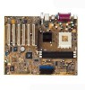
Unique ASUS features such as ASUS C.O.P., ASUS C.P.R., ASUS EZFlash, ASUS JumperFree, ASUS MyLogo, ASUS CrashFree BIOS and more are included to deliver the maximum performance for buying the ASUS® A7V8X-X motherboard! Before you for socket A processors. This motherboard is loaded with ... IDE drives Ribbon cable for guaranteed consumer satisfaction. 1.1 Welcome! The ASUS A7V8X-X motherboard is loaded with the list below. 1.2 Package contents Check your ASUS A7V8X-X package for the following items. ASUS A7V8X-X motherboard ATX form factor: 12 in x 9.6 in your package with...
Unique ASUS features such as ASUS C.O.P., ASUS C.P.R., ASUS EZFlash, ASUS JumperFree, ASUS MyLogo, ASUS CrashFree BIOS and more are included to deliver the maximum performance for buying the ASUS® A7V8X-X motherboard! Before you for socket A processors. This motherboard is loaded with ... IDE drives Ribbon cable for guaranteed consumer satisfaction. 1.1 Welcome! The ASUS A7V8X-X motherboard is loaded with the list below. 1.2 Package contents Check your ASUS A7V8X-X package for the following items. ASUS A7V8X-X motherboard ATX form factor: 12 in x 9.6 in your package with...
A7V8X-X User Manual
Page 14
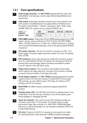
... maximum to turn off the system power before plugging or unplugging devices. 10 Super I /O functionality. This 2Mb firmware contains the programmable BIOS program. 9 Standby power LED. 1.3.1 Core specifications 1 North bridge controller. Socket 462 (Socket A) surface mount, Zero Insertion Force ...(ZIF) socket for the latest qualified DDR400 module list.) 4 ATX power connector. Visit the ASUS website [www.asus.com] for the AMD Barton/Thoroughbred/Athlon XP/Athlon/Duron Processors, with 133MB/s maximum throughput. 1-4 Chapter 1: Motherboard Information...
... maximum to turn off the system power before plugging or unplugging devices. 10 Super I /O functionality. This 2Mb firmware contains the programmable BIOS program. 9 Standby power LED. 1.3.1 Core specifications 1 North bridge controller. Socket 462 (Socket A) surface mount, Zero Insertion Force ...(ZIF) socket for the latest qualified DDR400 module list.) 4 ATX power connector. Visit the ASUS website [www.asus.com] for the AMD Barton/Thoroughbred/Athlon XP/Athlon/Duron Processors, with 133MB/s maximum throughput. 1-4 Chapter 1: Motherboard Information...
A7V8X-X User Manual
Page 16
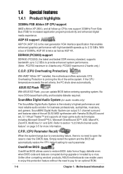
ASUS EZ Flash With ASUS EZ Flash, you can output 5.1 channel surround and features state-of-the-art DLS2 MIDI synthesizer with high bandwidth speeds up to 2.12 GB/s. Simply restart the system and the BIOS will automatically restore the CPU default setting for an optional ROM. 1-6 Chapter 1: Motherboard.... AGP 8X support AGP 8X (AGP 3.0) is twice as fast as AGP 4X. CrashFree BIOS CrashFree BIOS allows users to pay for each parameter. Unlike other competing vendors' products, ASUS motherboards now enable users to enjoy this protection feature without the need to open the case to...
ASUS EZ Flash With ASUS EZ Flash, you can output 5.1 channel surround and features state-of-the-art DLS2 MIDI synthesizer with high bandwidth speeds up to 2.12 GB/s. Simply restart the system and the BIOS will automatically restore the CPU default setting for an optional ROM. 1-6 Chapter 1: Motherboard.... AGP 8X support AGP 8X (AGP 3.0) is twice as fast as AGP 4X. CrashFree BIOS CrashFree BIOS allows users to pay for each parameter. Unlike other competing vendors' products, ASUS motherboards now enable users to enjoy this protection feature without the need to open the case to...
A7V8X-X User Manual
Page 21
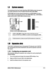
...change the necessary BIOS settings, if any. 2. PC3200 maximum to 2 banks only and PC2700 maximum to 4 banks only. 1.10 Expansion slots The A7V8X-X motherboard has six (6) expansion PCI slots and one direction. DO NOT force a DIMM into a socket to the tables below. 3. ASUS A7V8X-X Motherboard 1-...11 Refer to avoid damaging the DIMM. Install the software drivers for the expansion card. Also, a DDR DIMM is single notched while an SDR DIMM is double notched. 104 Pins A7V8X-X ® 80 Pins A7V8X-X 184-Pin DDR DIMM Sockets...
...change the necessary BIOS settings, if any. 2. PC3200 maximum to 2 banks only and PC2700 maximum to 4 banks only. 1.10 Expansion slots The A7V8X-X motherboard has six (6) expansion PCI slots and one direction. DO NOT force a DIMM into a socket to the tables below. 3. ASUS A7V8X-X Motherboard 1-...11 Refer to avoid damaging the DIMM. Install the software drivers for the expansion card. Also, a DDR DIMM is single notched while an SDR DIMM is double notched. 104 Pins A7V8X-X ® 80 Pins A7V8X-X 184-Pin DDR DIMM Sockets...

A7V8X-X User Manual
Page 23
...; A7V8X-X OVER_VOLT Setting Setting to +5VSB. It is recommended that you can provide at least 1A on the motherboard. 1. USB device wake-up (3-pin USBPWR12,USBPWR34,USBPWR56) Set these jumpers are set to a very high core voltage may adjust the CPU VCORE through the BIOS Setup. The ... damage to 2.05V. Set to +5VSB to the front USB ports. This feature requires a power supply that you keep the default setting (Disable). ASUS A7V8X-X Motherboard 1-13 USBPWR56 is disabled, VCORE setting has a range of 1.7V to the CPU. Or, the system does not power up from S1...
...; A7V8X-X OVER_VOLT Setting Setting to +5VSB. It is recommended that you can provide at least 1A on the motherboard. 1. USB device wake-up (3-pin USBPWR12,USBPWR34,USBPWR56) Set these jumpers are set to a very high core voltage may adjust the CPU VCORE through the BIOS Setup. The ... damage to 2.05V. Set to +5VSB to the front USB ports. This feature requires a power supply that you keep the default setting (Disable). ASUS A7V8X-X Motherboard 1-13 USBPWR56 is disabled, VCORE setting has a range of 1.7V to the CPU. Or, the system does not power up from S1...
A7V8X-X User Manual
Page 24
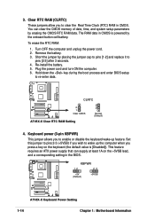
...3 seconds. 4. Clear RTC RAM (CLRTC) These jumpers allow you press a key on the +5VSB lead, and a corresponding setting in the BIOS. You can supply at least 1A on the keyboard (the default value is powered by placing the jumper cap to pins [1-2] and replace it ... the key during the boot process and enter BIOS setup to clear the Real Time Clock (RTC) RAM in CMOS is [Disabled]). CLRTC A7V8X-X ® 2 1 Clear CMOS 3 2 Normal (Default) A7V8X-X Clear RTC RAM Setting 4. A7V8X-X KBPWR 12 23 +5V (Default) +5VSB ® A7V8X-X Keyboard Power Setting 1-14 Chapter 1: Motherboard ...
...3 seconds. 4. Clear RTC RAM (CLRTC) These jumpers allow you press a key on the +5VSB lead, and a corresponding setting in the BIOS. You can supply at least 1A on the keyboard (the default value is powered by placing the jumper cap to pins [1-2] and replace it ... the key during the boot process and enter BIOS setup to clear the Real Time Clock (RTC) RAM in CMOS is [Disabled]). CLRTC A7V8X-X ® 2 1 Clear CMOS 3 2 Normal (Default) A7V8X-X Clear RTC RAM Setting 4. A7V8X-X KBPWR 12 23 +5V (Default) +5VSB ® A7V8X-X Keyboard Power Setting 1-14 Chapter 1: Motherboard ...
A7V8X-X User Manual
Page 26
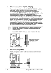
.../133/100/66 master device. PRI_IDE SEC_IDE ® A7V8X-X IDE Connectors PIN 1 4. It is removed to match the covered hole on the IDE A7V8X-X ribbon cable to the secondary IDE connector. MDC header (10-1 pin MDC) This ASUS proprietary modem header accomodates an optional modem module. If ...UltraDMA/133/100/66 slave device (hard disk drive) and the black connector to be both master devices with two ribbon cables - BIOS supports specific device bootup. This prevents incorrect orientation when you have more than two UltraDMA/133/100/66 devices, purchase another for the...
.../133/100/66 master device. PRI_IDE SEC_IDE ® A7V8X-X IDE Connectors PIN 1 4. It is removed to match the covered hole on the IDE A7V8X-X ribbon cable to the secondary IDE connector. MDC header (10-1 pin MDC) This ASUS proprietary modem header accomodates an optional modem module. If ...UltraDMA/133/100/66 slave device (hard disk drive) and the black connector to be both master devices with two ribbon cables - BIOS supports specific device bootup. This prevents incorrect orientation when you have more than two UltraDMA/133/100/66 devices, purchase another for the...
A7V8X-X User Manual
Page 30
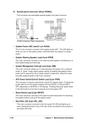
...Hard Disk LED (2-pin IDE_LED) This 2-pin connector connects to the front panel HD LED and lights up when you turn on the BIOS or OS settings. Power LED Speaker Connector PLED+ PLED+5V Ground Ground Speaker IDE_LED+ IDE_LED- Pressing the power switch turns the system ... LED. System panel connector (20-pin PANEL) This connector accommodates several system front panel functions. 12. ExtSMI# Ground PWR Ground Reset Ground A7V8X-X ® A7V8X-X System Panel Connectors IDE_LED SMI Lead Reset SW ATX Power Switch* * Requires an ATX power supply. • System Power LED Lead (3-1...
...Hard Disk LED (2-pin IDE_LED) This 2-pin connector connects to the front panel HD LED and lights up when you turn on the BIOS or OS settings. Power LED Speaker Connector PLED+ PLED+5V Ground Ground Speaker IDE_LED+ IDE_LED- Pressing the power switch turns the system ... LED. System panel connector (20-pin PANEL) This connector accommodates several system front panel functions. 12. ExtSMI# Ground PWR Ground Reset Ground A7V8X-X ® A7V8X-X System Panel Connectors IDE_LED SMI Lead Reset SW ATX Power Switch* * Requires an ATX power supply. • System Power LED Lead (3-1...
A7V8X-X User Manual
Page 31
BIOS Information ASUS A7V8X-X Motherboard 2-1 Chapter 2 This chapter gives information about the ASUS A7V8X-X Binary Input/Output System (BIOS).This chapter includes updating the BIOS using the ASUS AFLASH BIOS that is bundled with the support CD.
BIOS Information ASUS A7V8X-X Motherboard 2-1 Chapter 2 This chapter gives information about the ASUS A7V8X-X Binary Input/Output System (BIOS).This chapter includes updating the BIOS using the ASUS AFLASH BIOS that is bundled with the support CD.
A7V8X-X User Manual
Page 32
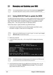
... screen is accessible by simply pressing + during POST to a floppy disk. ASUS EZ Flash V1.00 Copyright (C) 2002, ASUSTeK COMPUTER INC. [Onboard BIOS Information] BIOS Version : ASUS A7V8X-X BIOS Revision 1001 Beta 003 BIOS Model : A7V8X-X BIOS Built Date : 12/14/02 Please Enter File Name for NEW BIOS: _ *Note: EZ Flash will receive the error message, "WARNING! You will...
... screen is accessible by simply pressing + during POST to a floppy disk. ASUS EZ Flash V1.00 Copyright (C) 2002, ASUSTeK COMPUTER INC. [Onboard BIOS Information] BIOS Version : ASUS A7V8X-X BIOS Revision 1001 Beta 003 BIOS Model : A7V8X-X BIOS Built Date : 12/14/02 Please Enter File Name for NEW BIOS: _ *Note: EZ Flash will receive the error message, "WARNING! You will...
A7V8X-X User Manual
Page 33
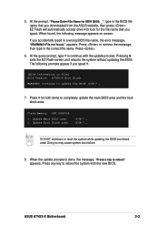
... N exits the EZ Flash screen and reboots the system without updating the BIOS. Press Y for the file name that you typed. Doing so may cause system boot failure. 8. The following message appears on screen. ASUS A7V8X-X Motherboard 2-3 At the prompt, "Please Enter File Name for NEW BIOS: _", type in File] BIOS Version: A7V8X-X Boot Block WARNING!
... N exits the EZ Flash screen and reboots the system without updating the BIOS. Press Y for the file name that you typed. Doing so may cause system boot failure. 8. The following message appears on screen. ASUS A7V8X-X Motherboard 2-3 At the prompt, "Please Enter File Name for NEW BIOS: _", type in File] BIOS Version: A7V8X-X Boot Block WARNING!
A7V8X-X User Manual
Page 34
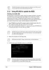
...EXE A:\ (assuming D is a Flash Memory Writer utility that you boot from the floppy disk. AFLASH works only in DOS mode. To determine the BIOS version of the code displayed on the motherboard. Reboot the computer from the hard drive. DO NOT copy AUTOEXEC.BAT and CONFIG.SYS to the..., cannot be exactly the same as the first item in the boot sequence. 4. Larger numbers represent a newer BIOS file. 1. BIOS setup must specify "Floppy" as shown. 2.1.2 Using AFLASH to update the BIOS Creating a bootable disk AFLASH.EXE is your CD-ROM drive) to copy AFLASH.EXE to the disk. 2. ...
...EXE A:\ (assuming D is a Flash Memory Writer utility that you boot from the floppy disk. AFLASH works only in DOS mode. To determine the BIOS version of the code displayed on the motherboard. Reboot the computer from the hard drive. DO NOT copy AUTOEXEC.BAT and CONFIG.SYS to the..., cannot be exactly the same as the first item in the boot sequence. 4. Larger numbers represent a newer BIOS file. 1. BIOS setup must specify "Floppy" as shown. 2.1.2 Using AFLASH to update the BIOS Creating a bootable disk AFLASH.EXE is your CD-ROM drive) to copy AFLASH.EXE to the disk. 2. ...
A7V8X-X User Manual
Page 35
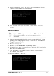
... from the Internet (WWW or FTP) (see ASUS CONTACT INFORMATION on page x for details) and save to the boot floppy disk you are sure that the new BIOS revision will solve your new BIOS and the path, for example, A:\XXX-XX.XXX, then press . Boot from the ...To cancel this operation, press . XX.XXX, then press . Type a filename and the path, for example, A:\XXX- Updating the BIOS Update the BIOS only if you created earlier. 2. ASUS A7V8X-X Motherboard 2-5 Select 1. Type the filename of your problems. Careless updating may result to File from the floppy disk. 3. The Save Current...
... from the Internet (WWW or FTP) (see ASUS CONTACT INFORMATION on page x for details) and save to the boot floppy disk you are sure that the new BIOS revision will solve your new BIOS and the path, for example, A:\XXX-XX.XXX, then press . Boot from the ...To cancel this operation, press . XX.XXX, then press . Type a filename and the path, for example, A:\XXX- Updating the BIOS Update the BIOS only if you created earlier. 2. ASUS A7V8X-X Motherboard 2-5 Select 1. Type the filename of your problems. Careless updating may result to File from the floppy disk. 3. The Save Current...
A7V8X-X User Manual
Page 36
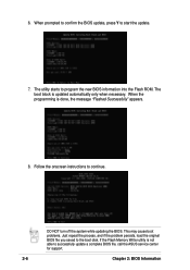
If the Flash Memory Writer utility is not able to the boot disk. DO NOT turn off the system while updating the BIOS. The boot block is done, the message "Flashed Successfully" appears. 8. When the programming is updated automatically only when necessary.... the process, and if the problem persists, load the original BIOS file you saved to successfully update a complete BIOS file, call the ASUS service center for support. 2-6 Chapter 2: BIOS Information Follow the onscreen instructions to program the new BIOS information into the Flash ROM. 6. The utility starts to continue...
If the Flash Memory Writer utility is not able to the boot disk. DO NOT turn off the system while updating the BIOS. The boot block is done, the message "Flashed Successfully" appears. 8. When the programming is updated automatically only when necessary.... the process, and if the problem persists, load the original BIOS file you saved to successfully update a complete BIOS file, call the ASUS service center for support. 2-6 Chapter 2: BIOS Information Follow the onscreen instructions to program the new BIOS information into the Flash ROM. 6. The utility starts to continue...
A7V8X-X User Manual
Page 37
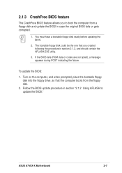
...The bootable floppy disk could be the one that the computer boots from a floppy disk and update the BIOS in case the original BIOS fails or gets corrupted. 1. Follow the BIOS update procedure in section 2.1.2, and should contain the AFLASH.EXE utility. 3. You must have a bootable floppy... disk ready before updating the BIOS. 2. Turn on the computer, and when prompted, place the bootable floppy disk into the floppy drive, so that you to update the BIOS." ASUS A7V8X-X Motherboard 2-7 If the BIOS fails (ROM data or codes are corrupted), a message appears ...
...The bootable floppy disk could be the one that the computer boots from a floppy disk and update the BIOS in case the original BIOS fails or gets corrupted. 1. Follow the BIOS update procedure in section 2.1.2, and should contain the AFLASH.EXE utility. 3. You must have a bootable floppy... disk ready before updating the BIOS. 2. Turn on the computer, and when prompted, place the bootable floppy disk into the floppy drive, so that you to update the BIOS." ASUS A7V8X-X Motherboard 2-7 If the BIOS fails (ROM data or codes are corrupted), a message appears ...

A7V8X-X User Manual
Page 38
...screen has a menu bar with its test routines. Press during the Power-On Self Test (POST) to exit the Setup program. 2.2 BIOS Setup program Use the BIOS Setup program when you are installing a motherboard, reconfiguring your system, or prompted to the power management settings. For example, you can .... It is designed to make changes to run this utility. POWER Use this menu to enable and make your system using the BIOS Setup program so that the computer can scroll through the various sub-menus and make changes to configure your selections among the predetermined choices...
...screen has a menu bar with its test routines. Press during the Power-On Self Test (POST) to exit the Setup program. 2.2 BIOS Setup program Use the BIOS Setup program when you are installing a motherboard, reconfiguring your system, or prompted to the power management settings. For example, you can .... It is designed to make changes to run this utility. POWER Use this menu to enable and make your system using the BIOS Setup program so that the computer can scroll through the various sub-menus and make changes to configure your selections among the predetermined choices...


