Motherboard DIY Troubleshooting Guide
Page 9
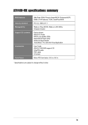
... A7V400-MX specifications summary BIOS features Industry standard Manageability Support CD contents Accessories Form Factor 2Mb Flash ROM, Phoenix Award BIOS, Enhanced ACPI, DMI2.0, PnP features, TCAV, CrashFree BIOS PCI 2.2, USB 2.0/1.1 Wake on Ring (WOR), Wake on LAN (WOL) Chassis intrusion Device drivers ASUS PC Probe ASUS Live Update Utility Award BIOS Flash Utility Adobe Acrobat Reader Trend Micro™ PC-cillin Anti-Virus Application User Guide ASUS A7V400-MX support CD UltraATA cable FDD cable I/O shield Micro-ATX form factor: 9.6 in x 9.6 in * Specifications are subject to change...
... A7V400-MX specifications summary BIOS features Industry standard Manageability Support CD contents Accessories Form Factor 2Mb Flash ROM, Phoenix Award BIOS, Enhanced ACPI, DMI2.0, PnP features, TCAV, CrashFree BIOS PCI 2.2, USB 2.0/1.1 Wake on Ring (WOR), Wake on LAN (WOL) Chassis intrusion Device drivers ASUS PC Probe ASUS Live Update Utility Award BIOS Flash Utility Adobe Acrobat Reader Trend Micro™ PC-cillin Anti-Virus Application User Guide ASUS A7V400-MX support CD UltraATA cable FDD cable I/O shield Micro-ATX form factor: 9.6 in x 9.6 in * Specifications are subject to change...
Motherboard DIY Troubleshooting Guide
Page 20
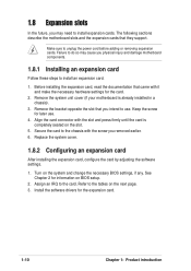
... and change the necessary BIOS settings, if any. Failure to do so may need to install expansion cards. Align the card connector with the slot and press firmly until the card is already installed in a chassis). 3. Replace the system cover. 1.8.2 Configuring an expansion card After installing the expansion card, configure the card by adjusting the software settings. 1. Refer to the tables on the slot. 5. See Chapter 2 for later use . Secure the card to the chassis...
... and change the necessary BIOS settings, if any. Failure to do so may need to install expansion cards. Align the card connector with the slot and press firmly until the card is already installed in a chassis). 3. Replace the system cover. 1.8.2 Configuring an expansion card After installing the expansion card, configure the card by adjusting the software settings. 1. Refer to the tables on the slot. 5. See Chapter 2 for later use . Secure the card to the chassis...

Motherboard DIY Troubleshooting Guide
Page 32
..." mode, where system activity is instantly decreased to save power and to the case-mounted reset switch for more than four seconds turns the system OFF. • Hard Disk Activity Lead (2-pin IDE LED) This connector supplies power to the system power LED. Speaker Power LED Connector +5 V PLED +5V Ground Ground Speaker HD_LED+ HD_LEDExtSMI# Ground PWRBIN Ground Reset Ground ® A7V400-MX IDELED SMI Lead Reset SW ATX Power Switch* A7V400-MX System Panel Connectors * Requires an ATX power supply. • System Power LED Lead (3-1 pin PLED) This 3-1 pin connector connects...
..." mode, where system activity is instantly decreased to save power and to the case-mounted reset switch for more than four seconds turns the system OFF. • Hard Disk Activity Lead (2-pin IDE LED) This connector supplies power to the system power LED. Speaker Power LED Connector +5 V PLED +5V Ground Ground Speaker HD_LED+ HD_LEDExtSMI# Ground PWRBIN Ground Reset Ground ® A7V400-MX IDELED SMI Lead Reset SW ATX Power Switch* A7V400-MX System Panel Connectors * Requires an ATX power supply. • System Power LED Lead (3-1 pin PLED) This 3-1 pin connector connects...

Motherboard DIY Troubleshooting Guide
Page 36
... the support CD that comes with onboard VGA, you will not see the screen display when the BIOS crashes even if you to update the motherboard BIOS in Windows® environment. On motherboards with the motherboard package. Click the Utilities tab, then click Install ASUS Update VX.XX.XX. Turn on this motherboard, install a VGA card into your system. The Drivers menu appears. 2. See page 3-3 for the Utilities menu screen. 3. Launch the utility from a floppy disk and update the BIOS in case...
... the support CD that comes with onboard VGA, you will not see the screen display when the BIOS crashes even if you to update the motherboard BIOS in Windows® environment. On motherboards with the motherboard package. Click the Utilities tab, then click Install ASUS Update VX.XX.XX. Turn on this motherboard, install a VGA card into your system. The Drivers menu appears. 2. See page 3-3 for the Utilities menu screen. 3. Launch the utility from a floppy disk and update the BIOS in case...

Motherboard DIY Troubleshooting Guide
Page 39
... BIOS setup screens and descriptions are for the highlighted field Saves changes and exit ASUS A7V400-MX motherboard user guide 2-7 Use this menu to make changes to exit the Setup program. The keys in the legend bar allow you see on the keyboard until the desired item is highlighted. 2.3.2 Legend bar At the bottom of the screen has a menu bar with the following selections: MAIN ADVANCED POWER BOOT EXIT Use this menu to enable...
... BIOS setup screens and descriptions are for the highlighted field Saves changes and exit ASUS A7V400-MX motherboard user guide 2-7 Use this menu to make changes to exit the Setup program. The keys in the legend bar allow you see on the keyboard until the desired item is highlighted. 2.3.2 Legend bar At the bottom of the screen has a menu bar with the following selections: MAIN ADVANCED POWER BOOT EXIT Use this menu to enable...
Motherboard DIY Troubleshooting Guide
Page 43
... setup BIOS automatically fills in order to enter the hard disk drive values manually. Select [CHS] in coordination with the [Manual] setting of undetected HDDs, pressing enter will detect the HDD and then open access to configure a hard disk drive, make sure you are removing a drive and not replacing it, select [None]. ASUS A7V400-MX motherboard user guide 2-11 In these cases, select [Manual] to automatically detect an IDE hard disk drive, if the hard drive is not already detected. If no drive is installed or...
... setup BIOS automatically fills in order to enter the hard disk drive values manually. Select [CHS] in coordination with the [Manual] setting of undetected HDDs, pressing enter will detect the HDD and then open access to configure a hard disk drive, make sure you are removing a drive and not replacing it, select [None]. ASUS A7V400-MX motherboard user guide 2-11 In these cases, select [Manual] to automatically detect an IDE hard disk drive, if the hard drive is not already detected. If no drive is installed or...

Motherboard DIY Troubleshooting Guide
Page 44
... sectors. The Main menu displays the hard disk drive field with more than 504MB storage capacity. When Logical Block Addressing (LBA) is enabled, the 28-bit addressing of cylinders, heads and sectors per track for the drive. Configuration options: [CHS] [LBA] [Large] [Auto] Capacity Displays the hard disk drive capacity in this field. Refer to the drive documentation to partition and format new IDE hard disk drives. After entering the IDE hard disk drive information into BIOS, use a disk utility, such...
... sectors. The Main menu displays the hard disk drive field with more than 504MB storage capacity. When Logical Block Addressing (LBA) is enabled, the 28-bit addressing of cylinders, heads and sectors per track for the drive. Configuration options: [CHS] [LBA] [Large] [Auto] Capacity Displays the hard disk drive capacity in this field. Refer to the drive documentation to partition and format new IDE hard disk drives. After entering the IDE hard disk drive information into BIOS, use a disk utility, such...

Motherboard DIY Troubleshooting Guide
Page 45
...ASUS A7V400-MX motherboard user guide 2-13 To make changes to this field to [Manual]. Transfer Mode This field selects the UDMA transfer mode. Configuration options: [Disabled] [Enabled] USB Legacy Support [Enabled] This motherboard supports Universal Serial Bus (USB) devices. When enabled, this item allows the system to select the DRAM clock. F1 : Help ↑↓ : Select Item -/+ : Change Value F5 : Setup Defaults ESC : Exit →← : Select Menu Enter : Select Sub-menu F10 : Save and Exit The Advanced menu displays the CPU type, speed, cache RAM, front side bus...
...ASUS A7V400-MX motherboard user guide 2-13 To make changes to this field to [Manual]. Transfer Mode This field selects the UDMA transfer mode. Configuration options: [Disabled] [Enabled] USB Legacy Support [Enabled] This motherboard supports Universal Serial Bus (USB) devices. When enabled, this item allows the system to select the DRAM clock. F1 : Help ↑↓ : Select Item -/+ : Change Value F5 : Setup Defaults ESC : Exit →← : Select Menu Enter : Select Sub-menu F10 : Save and Exit The Advanced menu displays the CPU type, speed, cache RAM, front side bus...
Motherboard DIY Troubleshooting Guide
Page 47
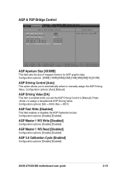
... [Disabled] Configuration options: [Disable] [Enabled] AGP 3.0 Calibration Cycle [Enabled] Configuration options: [Disable] [Enabled] ASUS A7V400-MX motherboard user guide 2-15 AGP & P2P Bridge Control AGP & P2P Bridge Control AGP Aperture Size AGP Driving Control AGP Driving Value AGP Fast Write AGP Master 1 WS Write AGP Master 1 WS Read AGP 3.0 Calibration Cycle [64MB] [Auto] DA [Disabled] [Disabled] [Disabled] [Enabled] Select Menu Item Specific Help F1 : Help ↑↓ : Select Item -/+ : Change Value F5 : Setup Defaults ESC : Exit →← : Select Menu Enter : Select...
... [Disabled] Configuration options: [Disable] [Enabled] AGP 3.0 Calibration Cycle [Enabled] Configuration options: [Disable] [Enabled] ASUS A7V400-MX motherboard user guide 2-15 AGP & P2P Bridge Control AGP & P2P Bridge Control AGP Aperture Size AGP Driving Control AGP Driving Value AGP Fast Write AGP Master 1 WS Write AGP Master 1 WS Read AGP 3.0 Calibration Cycle [64MB] [Auto] DA [Disabled] [Disabled] [Disabled] [Enabled] Select Menu Item Specific Help F1 : Help ↑↓ : Select Item -/+ : Change Value F5 : Setup Defaults ESC : Exit →← : Select Menu Enter : Select...

Motherboard DIY Troubleshooting Guide
Page 48
... DRAM clock. DRAM Clock/Drive Control DRAM Clock/Drive Control DRAM Timing DRAM CAS Latency Bank Interleave Pre-charge to Active (Trp) Active to Precharge (Tras) Active to CMD (Trcd) DRAM Burst Length DRAM Command Rate Write Recovery Time tWTR [Auto by SPD] [2.5] [Disabled] [5T] [7T] [5T] [4] [2T Command] [3T] [2T] Select Menu Item Specific Help F1 : Help ↑↓ : Select Item -/+ : Change Value F5 : Setup Defaults ESC : Exit →← : Select Menu Enter...
... DRAM clock. DRAM Clock/Drive Control DRAM Clock/Drive Control DRAM Timing DRAM CAS Latency Bank Interleave Pre-charge to Active (Trp) Active to Precharge (Tras) Active to CMD (Trcd) DRAM Burst Length DRAM Command Rate Write Recovery Time tWTR [Auto by SPD] [2.5] [Disabled] [5T] [7T] [5T] [4] [2T Command] [3T] [2T] Select Menu Item Specific Help F1 : Help ↑↓ : Select Item -/+ : Change Value F5 : Setup Defaults ESC : Exit →← : Select Menu Enter...

Motherboard DIY Troubleshooting Guide
Page 49
The VLink 8X technology allows high bandwidth connection between the North bridge and South bridge chipsets. Set this feature frees the PCI bus when the CPU is accessing 8-bit ISA cards. Configuration options: [Disabled] [Enabled] PCI Delay Transaction [Enabled] When set to [Enabled], this field to [Disabled] when using ISA cards that are not PCI 2.2 compliant. Configuration options: [Disabled] [Enabled] ASUS A7V400-MX motherboard user guide 2-17 DRAM Command Rate [2T Command] Configuration options: [2T Command] [1T Command] Write Recovery Time [3T] Configuration options: [2T] [3T] ...
The VLink 8X technology allows high bandwidth connection between the North bridge and South bridge chipsets. Set this feature frees the PCI bus when the CPU is accessing 8-bit ISA cards. Configuration options: [Disabled] [Enabled] PCI Delay Transaction [Enabled] When set to [Enabled], this field to [Disabled] when using ISA cards that are not PCI 2.2 compliant. Configuration options: [Disabled] [Enabled] ASUS A7V400-MX motherboard user guide 2-17 DRAM Command Rate [2T Command] Configuration options: [2T Command] [1T Command] Write Recovery Time [3T] Configuration options: [2T] [3T] ...

Motherboard DIY Troubleshooting Guide
Page 50
... enable the onboard IDE controllers. F1 : Help ↑↓ : Select Item -/+ : Change Value F5 : Setup Defaults ESC : Exit →← : Select Menu Enter : Select Sub-menu F10 : Save and Exit IDE DMA Transfer Access [Enabled] This option allows you set a PIO (Programmable Input/Output) mode for Primary IDE devices. Configuration options: [Auto] [Mode 0] [Mode 1] [Mode 2] [Mode 3] [Mode4] Secondary Master PIO [Auto] Secondary Slave PIO [Auto] This option lets you to enable the IDE DMA transfer access. Configuration options: [Disabled] [Auto] 2-18 Chapter 2: BIOS information...
... enable the onboard IDE controllers. F1 : Help ↑↓ : Select Item -/+ : Change Value F5 : Setup Defaults ESC : Exit →← : Select Menu Enter : Select Sub-menu F10 : Save and Exit IDE DMA Transfer Access [Enabled] This option allows you set a PIO (Programmable Input/Output) mode for Primary IDE devices. Configuration options: [Auto] [Mode 0] [Mode 1] [Mode 2] [Mode 3] [Mode4] Secondary Master PIO [Auto] Secondary Slave PIO [Auto] This option lets you to enable the IDE DMA transfer access. Configuration options: [Disabled] [Auto] 2-18 Chapter 2: BIOS information...

Motherboard DIY Troubleshooting Guide
Page 52
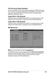
.... Configuration options: [5] [10] 2.5.3 PCI Configuration PCI Configuration Resources controlled by [Auto] When set the IRQ assignment for USB [Disabled] [Enabled] [Enabled] Select Menu Item Specific Help BIOS can automatically configure all Plug and Play devices. Setting this item to [Manual], allows manual assignment of IRQ addresses to select the onboard Game port address. Configuration options: [Auto] [Manual] 2-20 Chapter 2: BIOS information Configuration options: [Enabled] [Disabled] Onboard LAN Boot ROM [Disabled] This field allows you to Plug and Play devices using...
.... Configuration options: [5] [10] 2.5.3 PCI Configuration PCI Configuration Resources controlled by [Auto] When set the IRQ assignment for USB [Disabled] [Enabled] [Enabled] Select Menu Item Specific Help BIOS can automatically configure all Plug and Play devices. Setting this item to [Manual], allows manual assignment of IRQ addresses to select the onboard Game port address. Configuration options: [Auto] [Manual] 2-20 Chapter 2: BIOS information Configuration options: [Enabled] [Disabled] Onboard LAN Boot ROM [Disabled] This field allows you to Plug and Play devices using...
Motherboard DIY Troubleshooting Guide
Page 53
... USB [Enabled] Setting this problem. Select [PCI Device] to assign an IRQ address to [Enabled] corrects this option to [Enabled] allows the BIOS to [Manual]. Setting this option to [Enabled] allows the BIOS to [Reserved] reserves the IRQ address. Configuration options: [PCI Device] [Reserved] ASUS A7V400-MX motherboard user guide 2-21 Setting to automatically assign an IRQ address for VGA [Enabled] Setting this field to a Plug and Play device. If you are controlled manually, assign each system interrupt a type, depending on the type of device using a standard VGA card...
... USB [Enabled] Setting this problem. Select [PCI Device] to assign an IRQ address to [Enabled] corrects this option to [Enabled] allows the BIOS to [Manual]. Setting this option to [Enabled] allows the BIOS to [Reserved] reserves the IRQ address. Configuration options: [PCI Device] [Reserved] ASUS A7V400-MX motherboard user guide 2-21 Setting to automatically assign an IRQ address for VGA [Enabled] Setting this field to a Plug and Play device. If you are controlled manually, assign each system interrupt a type, depending on the type of device using a standard VGA card...

Motherboard DIY Troubleshooting Guide
Page 55
... Menu Enter : Select Sub-menu F10 : Save and Exit Power Up On PCI Devices [Disabled] When set to [Instant-off], the ATX switch can be used as a normal system power-off button when pressed for more than 4 seconds puts the system in sleep mode. Configuration options: [Blank Screen] [V/H SYNC+Blank] [DPMS support] C.O.P. The Display Power Management System (DPMS) feature allows the BIOS to have a dual function where pressing less than 4 seconds powers off features. Configuration options: [Disabled] [Enabled] ASUS A7V400-MX motherboard user guide...
... Menu Enter : Select Sub-menu F10 : Save and Exit Power Up On PCI Devices [Disabled] When set to [Instant-off], the ATX switch can be used as a normal system power-off button when pressed for more than 4 seconds puts the system in sleep mode. Configuration options: [Blank Screen] [V/H SYNC+Blank] [DPMS support] C.O.P. The Display Power Management System (DPMS) feature allows the BIOS to have a dual function where pressing less than 4 seconds powers off features. Configuration options: [Disabled] [Enabled] ASUS A7V400-MX motherboard user guide...

Motherboard DIY Troubleshooting Guide
Page 56
... [Disabled] for powering up from S3/S4/S5 [Disabled] When set to [Enabled], this parameter allows you to use the PS/2 mouse to turn on the system. Configuration options: [Disabled] [Enabled] PS2MS Wakeup from a keyboard stroke only after you enter the correct password. When this item again, then press twice. Configuration options: [Hot key] [Password] PS2KB Wakeup Password [Clear] This item appears when you select password as the wakeup method for manual setup. Configuration options: [Disabled] [Enabled...
... [Disabled] for powering up from S3/S4/S5 [Disabled] When set to [Enabled], this parameter allows you to use the PS/2 mouse to turn on the system. Configuration options: [Disabled] [Enabled] PS2MS Wakeup from a keyboard stroke only after you enter the correct password. When this item again, then press twice. Configuration options: [Hot key] [Password] PS2KB Wakeup Password [Clear] This item appears when you select password as the wakeup method for manual setup. Configuration options: [Disabled] [Enabled...

Motherboard DIY Troubleshooting Guide
Page 58
... : Setup Defaults ESC : Exit →← : Select Menu Enter : Select Sub-menu F10 : Save and Exit First/Second/Third/Fourth Boot Device The Boot Menu allows you to prevent reassigning of boot devices. 2.7 Boot menu First Boot Device Second Boot Device Third Boot Device Fourth Boot Device Plug & Play OS Reset Configuration Data Quick Power On Self Test Boot Up Floppy Seek Boot Up NumLock Status APIC Mode [HDD-0] [CDROM] [Floppy] [Disabled] [Yes] [Disabled] [Enabled] [Disabled] [On] [Enabled] Select Menu Item Specific Help Select your boot device priority. Configuration options...
... : Setup Defaults ESC : Exit →← : Select Menu Enter : Select Sub-menu F10 : Save and Exit First/Second/Third/Fourth Boot Device The Boot Menu allows you to prevent reassigning of boot devices. 2.7 Boot menu First Boot Device Second Boot Device Third Boot Device Fourth Boot Device Plug & Play OS Reset Configuration Data Quick Power On Self Test Boot Up Floppy Seek Boot Up NumLock Status APIC Mode [HDD-0] [CDROM] [Floppy] [Disabled] [Yes] [Disabled] [Enabled] [Disabled] [On] [Enabled] Select Menu Item Specific Help Select your boot device priority. Configuration options...

Motherboard DIY Troubleshooting Guide
Page 62
... item to install Click an icon to display more information. 3.2 Support CD information The support CD that came with the motherboard contains useful software and several utility drivers that enhance the motherboard features. Because motherboard settings and hardware options vary, use the setup procedures presented in your computer, browse the contents of the support CD to your hardware. Always install the latest OS version and corresponding updates so you...
... item to install Click an icon to display more information. 3.2 Support CD information The support CD that came with the motherboard contains useful software and several utility drivers that enhance the motherboard features. Because motherboard settings and hardware options vary, use the setup procedures presented in your computer, browse the contents of the support CD to your hardware. Always install the latest OS version and corresponding updates so you...
Motherboard DIY Troubleshooting Guide
Page 63
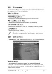
... computer systems vital components such as fan rotations, CPU temperature, and system voltages, and alerts you on specific operating system versions. 3.2.3 Utilities menu The Utilities menu shows the software applications that the motherboard supports. ASUS A7V400-MX motherboard user guide 3-3 VIA 4 in 1 Drivers This item installs the VIA 4-in-1 drivers. USB 2.0 Driver This item installs the USB 2.0 driver. VIA 10/100Mb LAN Driver Click this motherboard. 3.2.2 Drivers menu The drivers menu displays the available device drivers for this item to install the driver for the onboard VGA.
... computer systems vital components such as fan rotations, CPU temperature, and system voltages, and alerts you on specific operating system versions. 3.2.3 Utilities menu The Utilities menu shows the software applications that the motherboard supports. ASUS A7V400-MX motherboard user guide 3-3 VIA 4 in 1 Drivers This item installs the VIA 4-in-1 drivers. USB 2.0 Driver This item installs the USB 2.0 driver. VIA 10/100Mb LAN Driver Click this motherboard. 3.2.2 Drivers menu The drivers menu displays the available device drivers for this item to install the driver for the onboard VGA.

Motherboard DIY Troubleshooting Guide
Page 64
... viewing files saved in Portable Document Format (PDF). View the PC-cillin online help for detailed information. This utility requires an Internet connection either through a network or an Internet Service Provider (ISP). PC-CILLIN This item installs the PC-cillin anti-virus program. ASUS Screensaver This item installs the ASUS screensaver. 3.2.4 ASUS contact information Click the Contact tab to update the motherboard BIOS and drivers...
... viewing files saved in Portable Document Format (PDF). View the PC-cillin online help for detailed information. This utility requires an Internet connection either through a network or an Internet Service Provider (ISP). PC-CILLIN This item installs the PC-cillin anti-virus program. ASUS Screensaver This item installs the ASUS screensaver. 3.2.4 ASUS contact information Click the Contact tab to update the motherboard BIOS and drivers...


