
A7V333 User Manual
Page 5
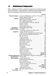
... 4.2.1 BIOS menu bar 54 4.2.2 Legend bar 54 4.3 Main Menu 56 4.3.1 Primary and Secondary Master/Slave 57 4.3.2 Keyboard Features 61 4.4 Advanced Menu 63 4.4.1 Chip Configuration 65 4.4.2 I/O Device Configuration 68 4.4.3 PCI Configuration 70 4.5 Power Menu 73 4.5.1 Power Up Control 75 4.5.2 Hardware Monitor 77 4.6 Boot Menu 78 4.7 Exit Menu 80 Chapter 5: Software support 1 5.1 Install an operating system 83 5.2 Support CD information 83 5.3 A7V333 Motherboard Support CD 84 5.4 Using the Promise Chip for RAID 0 or 1 86 5.5 Manual Installation of IDE/RAID Drivers 93 5.4 ASUS...
... 4.2.1 BIOS menu bar 54 4.2.2 Legend bar 54 4.3 Main Menu 56 4.3.1 Primary and Secondary Master/Slave 57 4.3.2 Keyboard Features 61 4.4 Advanced Menu 63 4.4.1 Chip Configuration 65 4.4.2 I/O Device Configuration 68 4.4.3 PCI Configuration 70 4.5 Power Menu 73 4.5.1 Power Up Control 75 4.5.2 Hardware Monitor 77 4.6 Boot Menu 78 4.7 Exit Menu 80 Chapter 5: Software support 1 5.1 Install an operating system 83 5.2 Support CD information 83 5.3 A7V333 Motherboard Support CD 84 5.4 Using the Promise Chip for RAID 0 or 1 86 5.5 Manual Installation of IDE/RAID Drivers 93 5.4 ASUS...

A7V333 User Manual
Page 12
... Dual Inline Memory Module (DDR DIMM) sockets to support up to 3GB of I /O controller supports a floppy disk drive, PS/2 keyboard, and PS/2 mouse. Supports UltraDMA133/100/66/33, PIO Modes 3 & 4, Bus Master IDE DMA Mode 2, and Enhanced IDE devices, such as DVDROM, CD-ROM, CD-R/RW, LS-120, and Tape Backup drives. Expansion: One AGP PRO 4X, four USB 2.0 ports, four USB 1.1 ports, five PCI slots, SPDIF digital audio connector, 1394 header, game connector, MS & SD headers, iPanel connector, front audio panel connector, smart card connector, infrared port. South Bridge Chipset...
... Dual Inline Memory Module (DDR DIMM) sockets to support up to 3GB of I /O controller supports a floppy disk drive, PS/2 keyboard, and PS/2 mouse. Supports UltraDMA133/100/66/33, PIO Modes 3 & 4, Bus Master IDE DMA Mode 2, and Enhanced IDE devices, such as DVDROM, CD-ROM, CD-R/RW, LS-120, and Tape Backup drives. Expansion: One AGP PRO 4X, four USB 2.0 ports, four USB 1.1 ports, five PCI slots, SPDIF digital audio connector, 1394 header, game connector, MS & SD headers, iPanel connector, front audio panel connector, smart card connector, infrared port. South Bridge Chipset...
A7V333 User Manual
Page 14
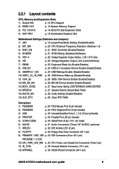
... the motherboard makes upgrading easy. Location Processor Support Socket A for AMD® Athlon™ and Duron™ Processors ....... 2 Feature Setting DIP Switches 9 Chipsets VIA® KT333 North Bridge 1 2Mbit Programmable Flash EEPROM 4 VIA® VT8233A South Bridge 11 Promise IDE RAID 0/1 Controller (Optional 8 Multi-I/O Controller 19 USB 2.0 Controller 28 1394 Controller (Optional 29 Main Memory 3 DDR DIMM Sockets (3GB 3 Expansion Slots 5 PCI Slots 26 1 Accelerated Graphics Port (AGP) 4X Slot 30 System I/O 1 Floppy Disk Drive Connector 18 2 IDE Connectors (Optional...
... the motherboard makes upgrading easy. Location Processor Support Socket A for AMD® Athlon™ and Duron™ Processors ....... 2 Feature Setting DIP Switches 9 Chipsets VIA® KT333 North Bridge 1 2Mbit Programmable Flash EEPROM 4 VIA® VT8233A South Bridge 11 Promise IDE RAID 0/1 Controller (Optional 8 Multi-I/O Controller 19 USB 2.0 Controller 28 1394 Controller (Optional 29 Main Memory 3 DDR DIMM Sockets (3GB 3 Expansion Slots 5 PCI Slots 26 1 Accelerated Graphics Port (AGP) 4X Slot 30 System I/O 1 Floppy Disk Drive Connector 18 2 IDE Connectors (Optional...
A7V333 User Manual
Page 21
...14 System Memory Support 3) PCI 1/2/3/4/5 p. 16 32-bit PCI Bus Expansion Slots 4) AGP PRO p. 18 Accelerated Graphics Slot Motherboard Settings (Switches and Jumpers) 1) JEN p. 19 JumperFree Mode Setting (Disable/Enable) 2) DIP_SW p. 20 CPU External Frequency Selection (Switches 1-6) 3) RAID_EN p. 21 RAID Controller (Enable/Disable) 4) ROMSIP p. 21 ROM Setting (Hardware/Software) 5) VID1-4 p. 22 Voltage Regulator Output Setting (1.85-1.675 volts) 6) VID p. 22 Voltage Regulator Output Limit (Limit/Unlimited) 7) KBWK p. 23 Keyboard Wake Up (Enable/Disable) 8) USB_EN p. 24 USB...
...14 System Memory Support 3) PCI 1/2/3/4/5 p. 16 32-bit PCI Bus Expansion Slots 4) AGP PRO p. 18 Accelerated Graphics Slot Motherboard Settings (Switches and Jumpers) 1) JEN p. 19 JumperFree Mode Setting (Disable/Enable) 2) DIP_SW p. 20 CPU External Frequency Selection (Switches 1-6) 3) RAID_EN p. 21 RAID Controller (Enable/Disable) 4) ROMSIP p. 21 ROM Setting (Hardware/Software) 5) VID1-4 p. 22 Voltage Regulator Output Setting (1.85-1.675 volts) 6) VID p. 22 Voltage Regulator Output Limit (Limit/Unlimited) 7) KBWK p. 23 Keyboard Wake Up (Enable/Disable) 8) USB_EN p. 24 USB...
A7V333 User Manual
Page 28
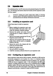
Failure to one Accelerated Graphics Port (AGP) slot.. Remove the system unit cover (if your power supply when adding or removing expansion cards or other system components. Replace the system cover. 7. If the motherboard has PCI audio onboard, an additional IRQ will be used . Unplug your motherboard is completely seated on the slot. 5. Remove the bracket opposite the PCI slot. Install the necessary software drivers for your motherboard also has MIDI enabled, another IRQ will be...
Failure to one Accelerated Graphics Port (AGP) slot.. Remove the system unit cover (if your power supply when adding or removing expansion cards or other system components. Replace the system cover. 7. If the motherboard has PCI audio onboard, an additional IRQ will be used . Unplug your motherboard is completely seated on the slot. 5. Remove the bracket opposite the PCI slot. Install the necessary software drivers for your motherboard also has MIDI enabled, another IRQ will be...

A7V333 User Manual
Page 29
... PCI slot 4 PCI slot 5 Onboard USB controller HC0 Onboard USB controller HC1 AGP Onboard Audio USB 2.0 Promise TI 1394 A - shared - - - - - for OS Win98, WinME; shared - - - - shared C - - - IMPORTANT! shared - - - - - Standard Interrupt Assignments IRQ Priority Standard Function 0 1 System Timer 1 2 Keyboard Controller 2 N/A Programmable Interrupt 3* 11 Communications Port (COM2) 4* 12 Communications Port (COM1) 5* 13 Sound Card (sometimes LPT2) 6 14 Floppy Disk Controller 7* 15 Printer Port (LPT1) 8 3 System CMOS/Real Time Clock 9* 4 ACPI Mode...
... PCI slot 4 PCI slot 5 Onboard USB controller HC0 Onboard USB controller HC1 AGP Onboard Audio USB 2.0 Promise TI 1394 A - shared - - - - - for OS Win98, WinME; shared - - - - shared C - - - IMPORTANT! shared - - - - - Standard Interrupt Assignments IRQ Priority Standard Function 0 1 System Timer 1 2 Keyboard Controller 2 N/A Programmable Interrupt 3* 11 Communications Port (COM2) 4* 12 Communications Port (COM1) 5* 13 Sound Card (sometimes LPT2) 6 14 Floppy Disk Controller 7* 15 Printer Port (LPT1) 8 3 System CMOS/Real Time Clock 9* 4 ACPI Mode...
A7V333 User Manual
Page 35
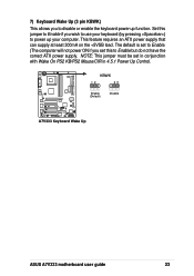
... default is set to Enable. (The computer will not power ON if you wish to use your keyboard (by pressing ) to power up function. NOTE: This jumper must be set this jumper to Enable but do not have the correct ATX power supply. Set this to Enable if you set in conjunction with Wake On PS2 KB/PS2 Mouse/CIR in 4.5.1 Power Up Control. A7V333 ® KBWK 12 23 Enable (Default) Disable A7V333 Keyboard Wake Up ASUS A7V333 motherboard user guide 23...
... default is set to Enable. (The computer will not power ON if you wish to use your keyboard (by pressing ) to power up function. NOTE: This jumper must be set this jumper to Enable but do not have the correct ATX power supply. Set this to Enable if you set in conjunction with Wake On PS2 KB/PS2 Mouse/CIR in 4.5.1 Power Up Control. A7V333 ® KBWK 12 23 Enable (Default) Disable A7V333 Keyboard Wake Up ASUS A7V333 motherboard user guide 23...

A7V333 User Manual
Page 36
...; A7V333 USB Wake Up Setting USBWP2_EN USBWP1_EN 12 23 WAKEUP ENABLE (Default) WAKEUP DISABLE 24 Chapter 2: Hardware information NOTE: This jumper activates rear panel ports USB20_12. Switching the jumper caps to [2-3] disables all device wakeup power to enable [1-2] for use with USB 2.0 compliant devices. The default is set to the USB ports. 8) USB 2.0 Compliant Device Enable (3 pin USB) This jumper enables or disables the Universal Serial Bus (USB) 2.0 capability. The circuit facilitates external power up from a USB device source. A7V333 ® A7V333 USB Setting USB_EN...
...; A7V333 USB Wake Up Setting USBWP2_EN USBWP1_EN 12 23 WAKEUP ENABLE (Default) WAKEUP DISABLE 24 Chapter 2: Hardware information NOTE: This jumper activates rear panel ports USB20_12. Switching the jumper caps to [2-3] disables all device wakeup power to enable [1-2] for use with USB 2.0 compliant devices. The default is set to the USB ports. 8) USB 2.0 Compliant Device Enable (3 pin USB) This jumper enables or disables the Universal Serial Bus (USB) 2.0 capability. The circuit facilitates external power up from a USB device source. A7V333 ® A7V333 USB Setting USB_EN...

A7V333 User Manual
Page 37
... power supply capability (+5VSB) whether under normal working conditions or in slow refresh; Set to +5VSB to allow wake up . power supply in low power mode) using the connected USB devices. The default setting for the three jumpers is 1-2 to +5VSB. The USB23_PWR jumper activates the internal header, USB2_3. Otherwise, the system does not power up from S3 sleep state (no power to CPU; system running in reduced power mode). ASUS A7V333 motherboard user guide 25 This feature requires an ATX power supply...
... power supply capability (+5VSB) whether under normal working conditions or in slow refresh; Set to +5VSB to allow wake up . power supply in low power mode) using the connected USB devices. The default setting for the three jumpers is 1-2 to +5VSB. The USB23_PWR jumper activates the internal header, USB2_3. Otherwise, the system does not power up from S3 sleep state (no power to CPU; system running in reduced power mode). ASUS A7V333 motherboard user guide 25 This feature requires an ATX power supply...

A7V333 User Manual
Page 40
...) Audio Setting (3 pin Audio_En) The onboard 6 channel audio chip may be enabled or disabled using a PCI audio card on any of date, time, and system setup parameters by erasing the CMOS RTC RAM data. You can clear the CMOS memory of the expansion slots. Remove the battery. 3. Re-install the battery. 5. Plug the power cord and turn ON the computer. 6. Disable the onboard audio system if using these jumpers. The RAM data in CMOS is powered by touching a conductive metal object to clear the Real Time Clock...
...) Audio Setting (3 pin Audio_En) The onboard 6 channel audio chip may be enabled or disabled using a PCI audio card on any of date, time, and system setup parameters by erasing the CMOS RTC RAM data. You can clear the CMOS memory of the expansion slots. Remove the battery. 3. Re-install the battery. 5. Plug the power cord and turn ON the computer. 6. Disable the onboard audio system if using these jumpers. The RAM data in CMOS is powered by touching a conductive metal object to clear the Real Time Clock...

A7V333 User Manual
Page 45
... the secondary IDE connector. they support hard disk drive devices only. See 5.4 Software Setup for the primary IDE connector and another on a SCSI drive and select the boot disk through BIOS. (See 4.6 Boot Menu.) Do not connect any other types of the cable to the Promise IDE connectors; NOTE! 9) Primary (Blue) / Secondary (Black) IDE Connectors (40-1 pin PRIMARY IDE and SECONDARY IDE) (40-1 pin PROMISE IDE1 and PROMISE2 IDE) The Primary and Secondary IDE connectors support the IDE hard disk ribbon cables supplied with two extra onboard IDE connectors: one...
... the secondary IDE connector. they support hard disk drive devices only. See 5.4 Software Setup for the primary IDE connector and another on a SCSI drive and select the boot disk through BIOS. (See 4.6 Boot Menu.) Do not connect any other types of the cable to the Promise IDE connectors; NOTE! 9) Primary (Blue) / Secondary (Black) IDE Connectors (40-1 pin PRIMARY IDE and SECONDARY IDE) (40-1 pin PROMISE IDE1 and PROMISE2 IDE) The Primary and Secondary IDE connectors support the IDE hard disk ribbon cables supplied with two extra onboard IDE connectors: one...

A7V333 User Manual
Page 59
... off. 3. Award BIOS Beep Codes Beep Meaning One short beep when displaying logo Long beeps in an endless loop One long beep followed by three short beeps High frequency beeps when system is equipped with a surge protector. 5. 3.1 Starting up or switch between orange and green after the system LED turns on the front of the system chassis. 4. After making all switches are using an ATX power supply, you press the ATX power switch. Connect the power cord to switch on the power supply as well...
... off. 3. Award BIOS Beep Codes Beep Meaning One short beep when displaying logo Long beeps in an endless loop One long beep followed by three short beeps High frequency beeps when system is equipped with a surge protector. 5. 3.1 Starting up or switch between orange and green after the system LED turns on the front of the system chassis. 4. After making all switches are using an ATX power supply, you press the ATX power switch. Connect the power cord to switch on the power supply as well...

A7V333 User Manual
Page 80
... cache. Configuration options: [Enabled] [Auto] USB Legacy Support [Auto] This motherboard supports Universal Serial Bus (USB) devices. CPU Level 1 Cache, CPU Level 2 Cache [Enabled] These fields allow you set this field is [Auto], so the CPU vcore voltage is set manually by the user. Otherwise, IRQ12 can be used for this field to [Disabled], the USB controller legacy mode is disabled whether or not you need to set to [Enabled]. The default of greater than 64MB, you are using OS/2 operating systems with installed DRAM of [Auto] allows...
... cache. Configuration options: [Enabled] [Auto] USB Legacy Support [Auto] This motherboard supports Universal Serial Bus (USB) devices. CPU Level 1 Cache, CPU Level 2 Cache [Enabled] These fields allow you set this field is [Auto], so the CPU vcore voltage is set manually by the user. Otherwise, IRQ12 can be used for this field to [Disabled], the USB controller legacy mode is disabled whether or not you need to set to [Enabled]. The default of greater than 64MB, you are using OS/2 operating systems with installed DRAM of [Auto] allows...

A7V333 User Manual
Page 83
...[Secondary] [Disabled] S2K Bus Driving Strength [Auto] This item controls the host bus between the AMD K7 processor and the north bridge. Configuration options: [Disabled] [Enabled] [Auto] ASUS A7V333 motherboard user guide 67 Configuration options: [Auto] [Manual] S2K Strobe P Control [2] S2K Strobe N Control [3] Useful test parameters. Configuration options: [Auto] [Manual] DQS P Contol [2] DQS N Contol [E] Useful test parameters. Configuration options: [Auto] [Manual] DQS output delay 4MSB [E] DQS output delay 4LSB [2] Useful test parameters. Onboard PCI IDE Controller [Both] This...
...[Secondary] [Disabled] S2K Bus Driving Strength [Auto] This item controls the host bus between the AMD K7 processor and the north bridge. Configuration options: [Disabled] [Enabled] [Auto] ASUS A7V333 motherboard user guide 67 Configuration options: [Auto] [Manual] S2K Strobe P Control [2] S2K Strobe N Control [3] Useful test parameters. Configuration options: [Auto] [Manual] DQS P Contol [2] DQS N Contol [E] Useful test parameters. Configuration options: [Auto] [Manual] DQS output delay 4MSB [E] DQS output delay 4LSB [2] Useful test parameters. Onboard PCI IDE Controller [Both] This...

A7V333 User Manual
Page 86
... 4: BIOS Setup 4.4.3 PCI Configuration Slot 1/5, 2, 3, 4 IRQ [Auto] These fields automatically assign the IRQ for each field is [Auto], which utilizes auto-routing to determine IRQ assignments. USB Function [Enabled] Set this field to [Enabled] if you are using standard VGA cards, leave this field to use Universal Serial Bus (USB) devices. If you want to the default setting [Disabled]. Configuration options: [Auto] [NA] [3] [4] [5] [7] [9] [10] [11] [12] [14] [15] PCI/VGA Palette Snoop [Disabled] Some non-standard VGA cards, like graphics accelerators or MPEG video cards...
... 4: BIOS Setup 4.4.3 PCI Configuration Slot 1/5, 2, 3, 4 IRQ [Auto] These fields automatically assign the IRQ for each field is [Auto], which utilizes auto-routing to determine IRQ assignments. USB Function [Enabled] Set this field to [Enabled] if you are using standard VGA cards, leave this field to use Universal Serial Bus (USB) devices. If you want to the default setting [Disabled]. Configuration options: [Auto] [NA] [3] [4] [5] [7] [9] [10] [11] [12] [14] [15] PCI/VGA Palette Snoop [Disabled] Some non-standard VGA cards, like graphics accelerators or MPEG video cards...
A7V333 User Manual
Page 101
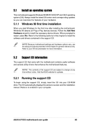
... device drivers. The CD automatically displays the welcome screen and the installation menus if Autorun is enabled in this chapter to change at any time without notice. Refer to the following sections in the support CD. ASUS A7V333 motherboard user guide 83 Because motherboard settings and hardware options vary, use the setup procedures presented in your CD-ROM drive. The contents of your hardware. 5.1.1 Windows 98 first time installation When you start Windows for updates...
... device drivers. The CD automatically displays the welcome screen and the installation menus if Autorun is enabled in this chapter to change at any time without notice. Refer to the following sections in the support CD. ASUS A7V333 motherboard user guide 83 Because motherboard settings and hardware options vary, use the setup procedures presented in your CD-ROM drive. The contents of your hardware. 5.1.1 Windows 98 first time installation When you start Windows for updates...

A7V333 User Manual
Page 102
... the C-Media Audio Driver and the sound system to support the C-Media Audio Chip and HRTF 3D Audio circuitry. • Realtek RTL 8139C PCI Fast Ethernet NIC Driver: Installs the Realtek fast ethernet network controller driver. • Promise FastTrak133 Controller: Installs the Promise FastTrak133 IDE/ RAID Controller Driver. • ASUS PC Probe Vx.xx: Installs a smart utility to monitor your computer's fan, temperature, and voltages. • ASUS Update Vx.xx: Instals a program that your CD-ROM drive and the support CD installation menu should appear.
... the C-Media Audio Driver and the sound system to support the C-Media Audio Chip and HRTF 3D Audio circuitry. • Realtek RTL 8139C PCI Fast Ethernet NIC Driver: Installs the Realtek fast ethernet network controller driver. • Promise FastTrak133 Controller: Installs the Promise FastTrak133 IDE/ RAID Controller Driver. • ASUS PC Probe Vx.xx: Installs a smart utility to monitor your computer's fan, temperature, and voltages. • ASUS Update Vx.xx: Instals a program that your CD-ROM drive and the support CD installation menu should appear.
A7V333 User Manual
Page 104
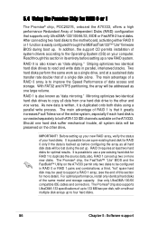
..." firmware BIOS during the set up a new RAID system. The Promise® chip also supports UltraDMA-133 specifications of up to use a pre-existing hard disk for more new disks. Striping optimizes two identical hard disk drives to the motherboard, activating either RAID 0 or 1 function is backed up your hard disks. After connecting two hard disks to read and write data in its entirety before configuring the array as one hard disk suffer mechanical trouble...
..." firmware BIOS during the set up a new RAID system. The Promise® chip also supports UltraDMA-133 specifications of up to use a pre-existing hard disk for more new disks. Striping optimizes two identical hard disk drives to the motherboard, activating either RAID 0 or 1 function is backed up your hard disks. After connecting two hard disks to read and write data in its entirety before configuring the array as one hard disk suffer mechanical trouble...
A7V333 User Manual
Page 111
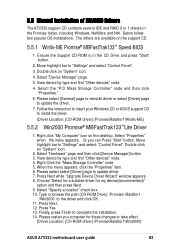
... update driver. 7. Select "Hardware" page and then click [Device Manager] button. 3. Please select select [Driver] page to "Settings" and select: "Control Panel". Press Next while "Upgrade Device Driver Wizard" window appears. 8. Select "Specify a location" check box. 10. Double click on the support CD. 5.5.1 Win9x-ME Promise® MBFastTrak133™ Speed BIOS 1. Type or browse the path {CD-ROM Drive}: \Promise \Raid0or1 \Win2000 to take effect. (Driver Location: {CD-ROM driver}:\Promise\Raid0or1\Win2000) ASUS A7V333 motherboard user guide...
... update driver. 7. Select "Hardware" page and then click [Device Manager] button. 3. Please select select [Driver] page to "Settings" and select: "Control Panel". Press Next while "Upgrade Device Driver Wizard" window appears. 8. Select "Specify a location" check box. 10. Double click on the support CD. 5.5.1 Win9x-ME Promise® MBFastTrak133™ Speed BIOS 1. Type or browse the path {CD-ROM Drive}: \Promise \Raid0or1 \Win2000 to take effect. (Driver Location: {CD-ROM driver}:\Promise\Raid0or1\Win2000) ASUS A7V333 motherboard user guide...

A7V333 User Manual
Page 131
... I/O connectivity at 100/200/400 Mbps. "Reboot" means to support next-generation auto-intensive PC applications such as scanners and cameras. ASUS A7V333 motherboard user guide 111 This serial bus defines both desktop and mobile manufacturers adopt these new technologies more expensive SCSI interface. AGP was designed to offer the necessary bandwidth and latency to compete with the PCI SoundBlaster specification. A copy of a file, directory...
... I/O connectivity at 100/200/400 Mbps. "Reboot" means to support next-generation auto-intensive PC applications such as scanners and cameras. ASUS A7V333 motherboard user guide 111 This serial bus defines both desktop and mobile manufacturers adopt these new technologies more expensive SCSI interface. AGP was designed to offer the necessary bandwidth and latency to compete with the PCI SoundBlaster specification. A copy of a file, directory...


