Motherboard DIY Troubleshooting Guide
Page 1
® A7V266 JumperFree™ DDR DRAM 266MHz FSB AGP Pro/4X Socket A Motherboard USER'S MANUAL
® A7V266 JumperFree™ DDR DRAM 266MHz FSB AGP Pro/4X Socket A Motherboard USER'S MANUAL

Motherboard DIY Troubleshooting Guide
Page 2
... FURNISHED FOR INFORMATIONAL USE ONLY, AND ARE SUBJECT TO CHANGE AT ANY TIME WITHOUT NOTICE, AND SHOULD NOT BE CONSTRUED AS A COMMITMENT BY ASUS. Product Name: ASUS A7V266 Manual Revision: 1.05 E766 Release Date: JUNE 2001 2 ASUS A7V266 User's Manual The product name and revision number are both printed on the following page. For previous or updated...
... FURNISHED FOR INFORMATIONAL USE ONLY, AND ARE SUBJECT TO CHANGE AT ANY TIME WITHOUT NOTICE, AND SHOULD NOT BE CONSTRUED AS A COMMITMENT BY ASUS. Product Name: ASUS A7V266 Manual Revision: 1.05 E766 Release Date: JUNE 2001 2 ASUS A7V266 User's Manual The product name and revision number are both printed on the following page. For previous or updated...

Motherboard DIY Troubleshooting Guide
Page 3
...) Notebook (Tel): +886-2-2890-7122 (English) Desktop/Server (Tel):+886-2-2890-7123 (English) Fax: +886-2-2893-7775 Email: tsd@asus.com.tw WWW: www.asus.com.tw FTP: ftp.asus.com.tw/pub/ASUS ASUS COMPUTER INTERNATIONAL (America) Marketing Address: 6737 Mowry Avenue, Mowry Business Center, Building 2 Newark, CA 94560, USA Fax: +1-510-608-4555... Fax: +49-2102-9599-11 Support (Email): www.asuscom.de/de/support (for online support) WWW: www.asuscom.de FTP: ftp.asuscom.de/pub/ASUSCOM ASUS A7V266 User's Manual 3
...) Notebook (Tel): +886-2-2890-7122 (English) Desktop/Server (Tel):+886-2-2890-7123 (English) Fax: +886-2-2893-7775 Email: tsd@asus.com.tw WWW: www.asus.com.tw FTP: ftp.asus.com.tw/pub/ASUS ASUS COMPUTER INTERNATIONAL (America) Marketing Address: 6737 Mowry Avenue, Mowry Business Center, Building 2 Newark, CA 94560, USA Fax: +1-510-608-4555... Fax: +49-2102-9599-11 Support (Email): www.asuscom.de/de/support (for online support) WWW: www.asuscom.de FTP: ftp.asuscom.de/pub/ASUSCOM ASUS A7V266 User's Manual 3

Motherboard DIY Troubleshooting Guide
Page 4
...the Computer System 45 4.1.2 Updating BIOS Procedures 47 4.2 BIOS Setup Program 49 4.2.1 BIOS Menu Bar 50 4.2.2 Legend Bar 50 4 ASUS A7V266 User's Manual HARDWARE SETUP 14 3.1 Motherboard Layout 14 3.2 Layout Contents 15 3.3 Hardware Setup Procedure 17 3.4 Motherboard Settings 17 3.5 System Memory ...Slot 30 3.8 Connectors 31 3.8.1 External Connectors 31 3.9 Starting Up the First Time 44 4. FEATURES 8 2.1 ASUS A7V266 Motherboard 8 2.1.1 Specifications 8 2.1.2 Performance 10 2.1.3 Intelligence 11 2.2 Motherboard Components 12 2.2.1 Component Locations 13 3. CONTENTS 1.
...the Computer System 45 4.1.2 Updating BIOS Procedures 47 4.2 BIOS Setup Program 49 4.2.1 BIOS Menu Bar 50 4.2.2 Legend Bar 50 4 ASUS A7V266 User's Manual HARDWARE SETUP 14 3.1 Motherboard Layout 14 3.2 Layout Contents 15 3.3 Hardware Setup Procedure 17 3.4 Motherboard Settings 17 3.5 System Memory ...Slot 30 3.8 Connectors 31 3.8.1 External Connectors 31 3.9 Starting Up the First Time 44 4. FEATURES 8 2.1 ASUS A7V266 Motherboard 8 2.1.1 Specifications 8 2.1.2 Performance 10 2.1.3 Intelligence 11 2.2 Motherboard Components 12 2.2.1 Component Locations 13 3. CONTENTS 1.

Motherboard DIY Troubleshooting Guide
Page 6
... approved by one or more of Communications. Cet appareil numérique de la classe B est conforme à la norme NMB-003 du Canada. 6 ASUS A7V266 User's Manual This Class B digital apparatus complies with FCC Rules Part 15. Operation is subject to the following measures: • Re-orient or relocate the receiving antenna...
... approved by one or more of Communications. Cet appareil numérique de la classe B est conforme à la norme NMB-003 du Canada. 6 ASUS A7V266 User's Manual This Class B digital apparatus complies with FCC Rules Part 15. Operation is subject to the following measures: • Re-orient or relocate the receiving antenna...
Motherboard DIY Troubleshooting Guide
Page 7
... for more detailed information about using a Smart Card. The TUSL2 supports the latest PC/SC compliant Smart Card Reader: the Read2-In-01. INTRODUCTION 2. APPENDIX Manual information and checklist Production information and specifications Instructions on setting up your package is divided into the following sections: 1. ASUS A7V266 User's Manual 7 INTRODUCTION Manual / Checklist 1. HARDWARE SETUP 4.
... for more detailed information about using a Smart Card. The TUSL2 supports the latest PC/SC compliant Smart Card Reader: the Read2-In-01. INTRODUCTION 2. APPENDIX Manual information and checklist Production information and specifications Instructions on setting up your package is divided into the following sections: 1. ASUS A7V266 User's Manual 7 INTRODUCTION Manual / Checklist 1. HARDWARE SETUP 4.

Motherboard DIY Troubleshooting Guide
Page 8
.... • PC Health Monitoring: Provides an easy way to physically transport commands and information between SMBus devices. 8 ASUS A7V266 User's Manual DDR DRAM is backward compatible with the highest bandwidth and lowest latency currently available and dramatically improves the memory system's ...; AGP Pro Slot: Comes with two connectors that support four IDE devices on two channels. FEATURES Specifications 2. FEATURES 2.1 ASUS A7V266 Motherboard The ASUS A7V266 motherboard is targeted diversely for six USB ports. • PC2100 / PC1600 DDR Support: Equipped with three root hubs for...
.... • PC Health Monitoring: Provides an easy way to physically transport commands and information between SMBus devices. 8 ASUS A7V266 User's Manual DDR DRAM is backward compatible with the highest bandwidth and lowest latency currently available and dramatically improves the memory system's ...; AGP Pro Slot: Comes with two connectors that support four IDE devices on two channels. FEATURES Specifications 2. FEATURES 2.1 ASUS A7V266 Motherboard The ASUS A7V266 motherboard is targeted diversely for six USB ports. • PC2100 / PC1600 DDR Support: Equipped with three root hubs for...

Motherboard DIY Troubleshooting Guide
Page 9
... Advanced Communication Riser card. The AFPANEL connector on the motherboard. 2. The Super I /O functions. The ACR is any standby power on the motherboard accommodates the ASUS iPanel. ASUS A7V266 User's Manual 9 This LED acts as a reminder to turn off the system power before plugging or unplugging devices to prevent damage to the motherboard, peripherals, and...
... Advanced Communication Riser card. The AFPANEL connector on the motherboard. 2. The Super I /O functions. The ACR is any standby power on the motherboard accommodates the ASUS iPanel. ASUS A7V266 User's Manual 9 This LED acts as a reminder to turn off the system power before plugging or unplugging devices to prevent damage to the motherboard, peripherals, and...
Motherboard DIY Troubleshooting Guide
Page 10
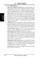
...mobile access services. • PC'99 Compliant: Both the BIOS and hardware levels of up to the memory and processor. 10 ASUS A7V266 User's Manual FEATURES Performance 2. This new memory technology increases performance by PC'99. • High-Speed Data Transfer Interface: Support for systems ... PCI audio controller that support OS Direct Power Management (OSPM) functionality. With these features employed in data transfer rates of ASUS smart series motherboards are based on the following high-level goals: Support for Plugn-Play compatibility and power management for configuring ...
...mobile access services. • PC'99 Compliant: Both the BIOS and hardware levels of up to the memory and processor. 10 ASUS A7V266 User's Manual FEATURES Performance 2. This new memory technology increases performance by PC'99. • High-Speed Data Transfer Interface: Support for systems ... PCI audio controller that support OS Direct Power Management (OSPM) functionality. With these features employed in data transfer rates of ASUS smart series motherboards are based on the following high-level goals: Support for Plugn-Play compatibility and power management for configuring ...

Motherboard DIY Troubleshooting Guide
Page 11
... power LED indicates the system status. • Remote Ring-On (requires modem): This allows a computer to critical motherboard components. ASUS A7V266 User's Manual 11 2. With this benefit on Pentium III and Celeron) to prevent system overheat and system damage. • Voltage Monitoring and ...can access vital information from their computers anywhere. • Temperature Monitoring and Alert: CPU temperature is monitored by the ASUS ASIC through the ASUS ASIC. FEATURES Intelligence 2. All fans are monitored to ensure stable voltage to be monitored for less than 4 seconds,...
... power LED indicates the system status. • Remote Ring-On (requires modem): This allows a computer to critical motherboard components. ASUS A7V266 User's Manual 11 2. With this benefit on Pentium III and Celeron) to prevent system overheat and system damage. • Voltage Monitoring and ...can access vital information from their computers anywhere. • Temperature Monitoring and Alert: CPU temperature is monitored by the ASUS ASIC through the ASUS ASIC. FEATURES Intelligence 2. All fans are monitored to ensure stable voltage to be monitored for less than 4 seconds,...

Motherboard DIY Troubleshooting Guide
Page 12
... VT8366 North Bridge 1 VIA® VT8233 South Bridge 9 ASUS System Monitor controller 7 C-Media® 6 Channel CMI8738 PCI...I/O 1 Floppy Disk Drive Connector 10 2 IDE Connectors (UltraDMA/100 Support 6 1 ASUS iPanel Connector 8 1 Parallel Port Top) 23 2 Serial Ports (COM1/COM2 Bottom) .../2 Keyboard Connector Bottom) 26 Hardware Monitoring System Voltage Monitoring (integrated in ASUS ASIC) ......... 7 3 Fan Power and Speed Monitoring Connectors Special Feature Onboard... audio models only) CMI8738 6-Channel Audio Controller 13 1 ASUS iPanel Audio Connector 14 1 Game/MIDI Port Top) 21...
... VT8366 North Bridge 1 VIA® VT8233 South Bridge 9 ASUS System Monitor controller 7 C-Media® 6 Channel CMI8738 PCI...I/O 1 Floppy Disk Drive Connector 10 2 IDE Connectors (UltraDMA/100 Support 6 1 ASUS iPanel Connector 8 1 Parallel Port Top) 23 2 Serial Ports (COM1/COM2 Bottom) .../2 Keyboard Connector Bottom) 26 Hardware Monitoring System Voltage Monitoring (integrated in ASUS ASIC) ......... 7 3 Fan Power and Speed Monitoring Connectors Special Feature Onboard... audio models only) CMI8738 6-Channel Audio Controller 13 1 ASUS iPanel Audio Connector 14 1 Game/MIDI Port Top) 21...

Motherboard DIY Troubleshooting Guide
Page 13
FEATURES Motherboard Parts 2. FEATURES 2.2.1 Component Locations 1 23 4 56 26 25 24 23 22 21 20 19 18 17 16 15 14 13 12 11 10 9 8 7 ASUS A7V266 User's Manual 13 2.
FEATURES Motherboard Parts 2. FEATURES 2.2.1 Component Locations 1 23 4 56 26 25 24 23 22 21 20 19 18 17 16 15 14 13 12 11 10 9 8 7 ASUS A7V266 User's Manual 13 2.

Motherboard DIY Troubleshooting Guide
Page 14
... CMI8738 6CH Audio Controller Accelerated Graphics Port (AGP Pro) PCI 1 DSW SYSCLK PCI 2 SMARTCARD PCI 3 CD PCI 4 PCI 5 ACR A7V266 VIA VT8233 Chipset CR2032 3V Lithium Cell CMOS Power ACRUSB SMB_CON JTPWR CLR_RTC ASUS FLOPPY ASIC with Hardware JEN Monitor CHA_FAN CHASSIS CHA IR_CON USB45_PWR IDELED USB23_PWR USB2_3 USB4_5 AFPANEL PANEL 14...
... CMI8738 6CH Audio Controller Accelerated Graphics Port (AGP Pro) PCI 1 DSW SYSCLK PCI 2 SMARTCARD PCI 3 CD PCI 4 PCI 5 ACR A7V266 VIA VT8233 Chipset CR2032 3V Lithium Cell CMOS Power ACRUSB SMB_CON JTPWR CLR_RTC ASUS FLOPPY ASIC with Hardware JEN Monitor CHA_FAN CHASSIS CHA IR_CON USB45_PWR IDELED USB23_PWR USB2_3 USB4_5 AFPANEL PANEL 14...

Motherboard DIY Troubleshooting Guide
Page 15
HARDWARE SETUP 3.2 Layout Contents Motherboard Settings 1) JEN p. 18 JumperFree Mode Setting (Disable / Enable) 2) DIP_SW p. 19 CPU External Frequency Selection (Switches 1-4) 3) DSW p. 20 Manual CPU Ratio Settings (Switches 1-5) 4) PALO_FREQ p. 20 FID setting (FID0-3) 5) JP1, JP2 p. 20 I/O Voltage Settings (2.5V/2.65V/2.75V/2.8V) 6) VID1, 2, 3, 4 p. 21 ...) 7) AUDIO p. 35 Audio Connectors (Three 1/8" AUDIO) (optional) 8) IDELED p. 36 IDE Activity LED (2 pin) 9) FLOPPY p. 36 Floppy Disk Drive Connector (34 pin) ASUS A7V266 User's Manual 15 H/W SETUP Layout Contents 3. 3.
HARDWARE SETUP 3.2 Layout Contents Motherboard Settings 1) JEN p. 18 JumperFree Mode Setting (Disable / Enable) 2) DIP_SW p. 19 CPU External Frequency Selection (Switches 1-4) 3) DSW p. 20 Manual CPU Ratio Settings (Switches 1-5) 4) PALO_FREQ p. 20 FID setting (FID0-3) 5) JP1, JP2 p. 20 I/O Voltage Settings (2.5V/2.65V/2.75V/2.8V) 6) VID1, 2, 3, 4 p. 21 ...) 7) AUDIO p. 35 Audio Connectors (Three 1/8" AUDIO) (optional) 8) IDELED p. 36 IDE Activity LED (2 pin) 9) FLOPPY p. 36 Floppy Disk Drive Connector (34 pin) ASUS A7V266 User's Manual 15 H/W SETUP Layout Contents 3. 3.

Motherboard DIY Troubleshooting Guide
Page 16
H/W SETUP Layout Contents 16 ASUS A7V266 User's Manual 3. HARDWARE SETUP 10) PRIMARY IDE SECONDARY IDE 11) CPU/PWR/CHA_FAN 12) USB2_3 / USB4_5 13) IR_CON 14) AFPANEL 15) ATXPWR 16) SMB 17) CD/AUX/... (Two 40-1 pin) p. 38 CPU, Power, and Chassis Fan Connectors (Three 3 pin) p. 38 USB Headers (10-1 pin) p. 39 Standard Infrared Module Connector (10-1 pin) p. 39 ASUS iPanel Connector (12-1 pin) p. 40 ATX Power Supply Connector (20 pin) p. 40 SMBus Connector (5-1 pin) p. 41 Internal Audio Connectors (Three 4-1 pin) (optional) p. 41 Internal Microphone...
H/W SETUP Layout Contents 16 ASUS A7V266 User's Manual 3. HARDWARE SETUP 10) PRIMARY IDE SECONDARY IDE 11) CPU/PWR/CHA_FAN 12) USB2_3 / USB4_5 13) IR_CON 14) AFPANEL 15) ATXPWR 16) SMB 17) CD/AUX/... (Two 40-1 pin) p. 38 CPU, Power, and Chassis Fan Connectors (Three 3 pin) p. 38 USB Headers (10-1 pin) p. 39 Standard Infrared Module Connector (10-1 pin) p. 39 ASUS iPanel Connector (12-1 pin) p. 40 ATX Power Supply Connector (20 pin) p. 40 SMBus Connector (5-1 pin) p. 41 Internal Audio Connectors (Three 4-1 pin) (optional) p. 41 Internal Microphone...

Motherboard DIY Troubleshooting Guide
Page 17
3. Computer motherboards and expansion cards contain very delicate Integrated Circuit (IC) chips. See illustration below.) 3. H/W SETUP Motherboard Settings 01 01 01 A7V266 A7V266 Onboard LED LED ON Standby Power OFF Powered Off ASUS A7V266 User's Manual 17 Install the Central Processing Unit (CPU) 4. Configure the BIOS parameter settings 3.4 Motherboard Settings This section tells you install or...
3. Computer motherboards and expansion cards contain very delicate Integrated Circuit (IC) chips. See illustration below.) 3. H/W SETUP Motherboard Settings 01 01 01 A7V266 A7V266 Onboard LED LED ON Standby Power OFF Powered Off ASUS A7V266 User's Manual 17 Install the Central Processing Unit (CPU) 4. Configure the BIOS parameter settings 3.4 Motherboard Settings This section tells you install or...

Motherboard DIY Troubleshooting Guide
Page 18
...The illustration below shows all DIP switches (DIP_SW) to OFF. 18 ASUS A7V266 User's Manual Setting JEN Enable (JumperFree) [2-3] (default) Disable (Jumper Mode) [1-2] JEN CPU_RATIO A7V266 ON ON 12345 OFF SYSCLK ON 1234 ON OFF 12 23 A7V266 Jumper Mode Setting Jumper Mode Jumper Free (Default) NOTE: In JumperFree...the switch's position. H/W SETUP Motherboard Settings 01 01 01 01 01 01 3. CPU_RATIO ON 12345 ON OFF A7V266 SYSCLK ON 1234 ON OFF A7V266 DIP Switch 1) JumperFree™ Mode (JEN) This jumper allows you to be made through the DIP switches. 3.
...The illustration below shows all DIP switches (DIP_SW) to OFF. 18 ASUS A7V266 User's Manual Setting JEN Enable (JumperFree) [2-3] (default) Disable (Jumper Mode) [1-2] JEN CPU_RATIO A7V266 ON ON 12345 OFF SYSCLK ON 1234 ON OFF 12 23 A7V266 Jumper Mode Setting Jumper Mode Jumper Free (Default) NOTE: In JumperFree...the switch's position. H/W SETUP Motherboard Settings 01 01 01 01 01 01 3. CPU_RATIO ON 12345 ON OFF A7V266 SYSCLK ON 1234 ON OFF A7V266 DIP Switch 1) JumperFree™ Mode (JEN) This jumper allows you to be made through the DIP switches. 3.

Motherboard DIY Troubleshooting Guide
Page 19
... SYSCLK ON 1234 ON 1234 ON 1234 ON 1234 CPU 100MHz 133.33MHz 140MHz AGP 60.67MHz 66.67MHz 70MHz (JumperFree Mode) A7V266 PCI 33.33MHz 33.33MHz 35MHz A7V266 CPU External Frequency Selection WARNING! IMPORTANT: 1. Overclocking the processor is enabled, use the clock multiplier to User Define under 4.4 Advanced Menu... set the CPU Frequency.) CPU_RATIO ON ON ON ON 12345 CPU_RATIO 8X ON 12345 8.5X ON 12345 9X ON 12345 9.5X 12345 12345 12345 A7V266 CPU_RATIO 10X 10.5X (JumperFree Mode) A7V266 CPU External Clock (BUS) Frequency Selection ASUS A7V266 User's Manual 19
... SYSCLK ON 1234 ON 1234 ON 1234 ON 1234 CPU 100MHz 133.33MHz 140MHz AGP 60.67MHz 66.67MHz 70MHz (JumperFree Mode) A7V266 PCI 33.33MHz 33.33MHz 35MHz A7V266 CPU External Frequency Selection WARNING! IMPORTANT: 1. Overclocking the processor is enabled, use the clock multiplier to User Define under 4.4 Advanced Menu... set the CPU Frequency.) CPU_RATIO ON ON ON ON 12345 CPU_RATIO 8X ON 12345 8.5X ON 12345 9X ON 12345 9.5X 12345 12345 12345 A7V266 CPU_RATIO 10X 10.5X (JumperFree Mode) A7V266 CPU External Clock (BUS) Frequency Selection ASUS A7V266 User's Manual 19

Motherboard DIY Troubleshooting Guide
Page 20
... The factory default setting, [2-3], is : JP1 [2-3] and JP2 [1-2], 2.65 volts. A7V266 A7V266 Voltage Setting JP1/JP2 12 3 JP1 JP2 12 3 12 3 2.5V 2.65V 2.75V (Default) 12 3 2.8V 20 ASUS A7V266 User's Manual The Palomino processor will only function on this motherboard after the jumpers are adjusted to another,... internal frequency between standard and new AMD CPUs. PALO_FREQ FID0 FID1 FID2 FID3 123 123 FID0 FID1 FID2 FID3 PALOMINO ATHLON/DURON A7V266 (Default) A7V266 PALO_FREQ Setting 01 01 01 01 01 01 5) I/O Voltage Settings (JP1, JP2) These jumpers allow you to select the ...
... The factory default setting, [2-3], is : JP1 [2-3] and JP2 [1-2], 2.65 volts. A7V266 A7V266 Voltage Setting JP1/JP2 12 3 JP1 JP2 12 3 12 3 2.5V 2.65V 2.75V (Default) 12 3 2.8V 20 ASUS A7V266 User's Manual The Palomino processor will only function on this motherboard after the jumpers are adjusted to another,... internal frequency between standard and new AMD CPUs. PALO_FREQ FID0 FID1 FID2 FID3 123 123 FID0 FID1 FID2 FID3 PALOMINO ATHLON/DURON A7V266 (Default) A7V266 PALO_FREQ Setting 01 01 01 01 01 01 5) I/O Voltage Settings (JP1, JP2) These jumpers allow you to select the ...

Motherboard DIY Troubleshooting Guide
Page 21
A7V266 A7V266 CPU Core Voltage Selection 123 VID4 VID3 VID2 VID1 1.85/1.825Volts 123 1.8/1.775Volts 123 VID4 VID3 VID2 VID1 1.75/1.725Volts 123 1.7/1.675Volts 7) Bass Center Setting (... signals among the internal leads in the Line-In, Line-Out, Mic female sockets. A7V266 A7V266 Bass Center Setting BCS 12 23 type 1 Bass (CENTER/BASS) (Default) type 2 Bass (BASS/CENTER) ASUS A7V266 User's Manual 21 It is generated according to manually adjust the CPU core voltage. For each jumper setting, there are two voltage options...
A7V266 A7V266 CPU Core Voltage Selection 123 VID4 VID3 VID2 VID1 1.85/1.825Volts 123 1.8/1.775Volts 123 VID4 VID3 VID2 VID1 1.75/1.725Volts 123 1.7/1.675Volts 7) Bass Center Setting (... signals among the internal leads in the Line-In, Line-Out, Mic female sockets. A7V266 A7V266 Bass Center Setting BCS 12 23 type 1 Bass (CENTER/BASS) (Default) type 2 Bass (BASS/CENTER) ASUS A7V266 User's Manual 21 It is generated according to manually adjust the CPU core voltage. For each jumper setting, there are two voltage options...


