Motherboard DIY Troubleshooting Guide
Page 7
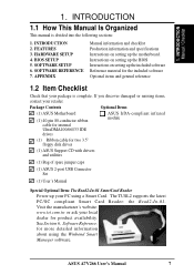
...Production information and specifications Instructions on setting up the included software Reference material for more detailed information about using a Smart Card. ASUS A7V266 User's Manual 7 INTRODUCTION 2. HARDWARE SETUP 4. The TUSL2 supports the latest PC/SC compliant Smart Card Reader: the Read2... 1.2 Item Checklist Check that your local dealer for two 3.5" floppy disk drives (1) ASUS Support CD with drivers and utilities (1) Bag of spare jumper caps (1) ASUS 2-port USB Connector Set (1) User's Manual Special Optional Item: The Read2-In-01 SmartCard Reader Power...
...Production information and specifications Instructions on setting up the included software Reference material for more detailed information about using a Smart Card. ASUS A7V266 User's Manual 7 INTRODUCTION 2. HARDWARE SETUP 4. The TUSL2 supports the latest PC/SC compliant Smart Card Reader: the Read2... 1.2 Item Checklist Check that your local dealer for two 3.5" floppy disk drives (1) ASUS Support CD with drivers and utilities (1) Bag of spare jumper caps (1) ASUS 2-port USB Connector Set (1) User's Manual Special Optional Item: The Read2-In-01 SmartCard Reader Power...

Motherboard DIY Troubleshooting Guide
Page 8
... supporting 133MHz 4X mode. The slot is the newest memory standard with the motherboard board to 3GB of DDR DRAM. FEATURES 2.1 ASUS A7V266 Motherboard The ASUS A7V266 motherboard is targeted diversely for six USB ports. • PC2100 / PC1600 DDR Support: Equipped with three root hubs for home PCs, workstations and servers. Powered by AMD®...
... supporting 133MHz 4X mode. The slot is the newest memory standard with the motherboard board to 3GB of DDR DRAM. FEATURES 2.1 ASUS A7V266 Motherboard The ASUS A7V266 motherboard is targeted diversely for six USB ports. • PC2100 / PC1600 DDR Support: Equipped with three root hubs for home PCs, workstations and servers. Powered by AMD®...

Motherboard DIY Troubleshooting Guide
Page 9
...throughput. • Advanced Communication Riser (ACR): Features an ACR slot for wireless connections. ASUS A7V266 User's Manual 9 2. The Super I /O functions. The ACR is any standby power on the motherboard accommodates the ASUS iPanel. FEATURES Specifications 2. This LED acts as a reminder to turn off the system ...card. Provides two high-speed UART compatible serial ports and one parallel port with system diagnostic display area, system status LEDs, USB ports, and hot keys. The AFPANEL connector on the motherboard. UART2 can also be directed from COM2 to -access box ...
...throughput. • Advanced Communication Riser (ACR): Features an ACR slot for wireless connections. ASUS A7V266 User's Manual 9 2. The Super I /O functions. The ACR is any standby power on the motherboard accommodates the ASUS iPanel. FEATURES Specifications 2. This LED acts as a reminder to turn off the system ...card. Provides two high-speed UART compatible serial ports and one parallel port with system diagnostic display area, system status LEDs, USB ports, and hot keys. The AFPANEL connector on the motherboard. UART2 can also be directed from COM2 to -access box ...

Motherboard DIY Troubleshooting Guide
Page 12
...I/O 1 Floppy Disk Drive Connector 10 2 IDE Connectors (UltraDMA/100 Support 6 1 ASUS iPanel Connector 8 1 Parallel Port Top) 23 2 Serial Ports (COM1/COM2 Bottom) 22, 24 USB Connectors (Port 0 & Port 1 Bottom) 25 USB Connectors (Ports 2/3/4/5 11 1 PS/2 Mouse Connector Top) 26 1 PS/2 Keyboard ... 13 1 ASUS iPanel Audio Connector 14 1 Game/MIDI Port Top) 21 1 Line Out Connector Bottom, left) 21 1 Line In Connector Bottom, center) 21 1 Microphone Connector Bottom, right) 21 Internal Audio Connectors Power ATX Power Supply Connector 5 Form Factor ATX 12 ASUS A7V266 User's Manual...
...I/O 1 Floppy Disk Drive Connector 10 2 IDE Connectors (UltraDMA/100 Support 6 1 ASUS iPanel Connector 8 1 Parallel Port Top) 23 2 Serial Ports (COM1/COM2 Bottom) 22, 24 USB Connectors (Port 0 & Port 1 Bottom) 25 USB Connectors (Ports 2/3/4/5 11 1 PS/2 Mouse Connector Top) 26 1 PS/2 Keyboard ... 13 1 ASUS iPanel Audio Connector 14 1 Game/MIDI Port Top) 21 1 Line Out Connector Bottom, left) 21 1 Line In Connector Bottom, center) 21 1 Microphone Connector Bottom, right) 21 Internal Audio Connectors Power ATX Power Supply Connector 5 Form Factor ATX 12 ASUS A7V266 User's Manual...

Motherboard DIY Troubleshooting Guide
Page 15
... Type 2) BASS/CENTER 8) KBWK p. 22 Keyboard Power Up (Enable / Disable) 9) ACRUSB1, ACRUSB2 p. 22 ACR/USB Selection (USB to Conn. / USB on ACR) 10) USB01_PWR p. 23 USB Device Wake-up (+5V / +5VSB) USB23_PWR USB45_PWR 11) CLR_RTC p. 24 Clear RTC RAM (2 pin contact) 12)... Connectors (Three 1/8" AUDIO) (optional) 8) IDELED p. 36 IDE Activity LED (2 pin) 9) FLOPPY p. 36 Floppy Disk Drive Connector (34 pin) ASUS A7V266 User's Manual 15 HARDWARE SETUP 3.2 Layout Contents Motherboard Settings 1) JEN p. 18 JumperFree Mode Setting (Disable / Enable) 2) DIP_SW p. 19 CPU External ...
... Type 2) BASS/CENTER 8) KBWK p. 22 Keyboard Power Up (Enable / Disable) 9) ACRUSB1, ACRUSB2 p. 22 ACR/USB Selection (USB to Conn. / USB on ACR) 10) USB01_PWR p. 23 USB Device Wake-up (+5V / +5VSB) USB23_PWR USB45_PWR 11) CLR_RTC p. 24 Clear RTC RAM (2 pin contact) 12)... Connectors (Three 1/8" AUDIO) (optional) 8) IDELED p. 36 IDE Activity LED (2 pin) 9) FLOPPY p. 36 Floppy Disk Drive Connector (34 pin) ASUS A7V266 User's Manual 15 HARDWARE SETUP 3.2 Layout Contents Motherboard Settings 1) JEN p. 18 JumperFree Mode Setting (Disable / Enable) 2) DIP_SW p. 19 CPU External ...

Motherboard DIY Troubleshooting Guide
Page 16
H/W SETUP Layout Contents 16 ASUS A7V266 User's Manual 3. HARDWARE SETUP 10) PRIMARY IDE SECONDARY ...-1 pin) p. 38 CPU, Power, and Chassis Fan Connectors (Three 3 pin) p. 38 USB Headers (10-1 pin) p. 39 Standard Infrared Module Connector (10-1 pin) p. 39 ASUS iPanel Connector (12-1 pin) p. 40 ATX Power Supply Connector (20 pin) p. 40 SMBus... pin) p. 43 Digital audio Interfaces (2 pin) (optional) p. 43 Chassis Intrusion Lead (2 pin) p. 44 ASUS iPanel Audio Connector (10-1 pin) p. 44 ASUS SmartCard Connector (14-1 pin) p. 45 System Power LED Lead (3 pin) p. 45 System Keyboard Lock Switch Lead...
H/W SETUP Layout Contents 16 ASUS A7V266 User's Manual 3. HARDWARE SETUP 10) PRIMARY IDE SECONDARY ...-1 pin) p. 38 CPU, Power, and Chassis Fan Connectors (Three 3 pin) p. 38 USB Headers (10-1 pin) p. 39 Standard Infrared Module Connector (10-1 pin) p. 39 ASUS iPanel Connector (12-1 pin) p. 40 ATX Power Supply Connector (20 pin) p. 40 SMBus... pin) p. 43 Digital audio Interfaces (2 pin) (optional) p. 43 Chassis Intrusion Lead (2 pin) p. 44 ASUS iPanel Audio Connector (10-1 pin) p. 44 ASUS SmartCard Connector (14-1 pin) p. 45 System Power LED Lead (3 pin) p. 45 System Keyboard Lock Switch Lead...

Motherboard DIY Troubleshooting Guide
Page 22
... H/W SETUP Motherboard Settings A7V266 A7V266 USB/ACR Selection ACRUSB 12 23 USB to pins 2-3 activates the Advanced Communication Riser (ACR) slot. Set this to activate USB port 3. Setting Enable Disable KBWK [1-2] (default) [2-3] KBWK 12 Enable (Default) 23 Disable A7V266 A7V266 Keyboard Wake Up 9) ACR/USB Selection (ACRUSB1, ACRUSB2)...jumpers is 1-2. (NOTE: The USB port 2 is set to power up function. Setting the jumpers to Conn. 01 01 01 01 01 01 3. This feature requires an ATX power supply that can supply at least 300mA on ACR 22 ASUS A7V266 User's Manual
... H/W SETUP Motherboard Settings A7V266 A7V266 USB/ACR Selection ACRUSB 12 23 USB to pins 2-3 activates the Advanced Communication Riser (ACR) slot. Set this to activate USB port 3. Setting Enable Disable KBWK [1-2] (default) [2-3] KBWK 12 Enable (Default) 23 Disable A7V266 A7V266 Keyboard Wake Up 9) ACR/USB Selection (ACRUSB1, ACRUSB2)...jumpers is 1-2. (NOTE: The USB port 2 is set to power up function. Setting the jumpers to Conn. 01 01 01 01 01 01 3. This feature requires an ATX power supply that can supply at least 300mA on ACR 22 ASUS A7V266 User's Manual

Motherboard DIY Troubleshooting Guide
Page 23
... capability (+5VSB) whether under normal working conditions or in low power mode) using the connected USB devices. H/W SETUP Motherboard Settings ASUS A7V266 User's Manual 23 3. NOTES: 1. system running in sleep mode. 01 01 01 12 23 USB01_PWR +5V +5VSB A7V266 A7V266 USB Device Wake Up 12 23 USB23_PWR USB45_PWR +5V +5VSB 3. Set to +5VSB to CPU...
... capability (+5VSB) whether under normal working conditions or in low power mode) using the connected USB devices. H/W SETUP Motherboard Settings ASUS A7V266 User's Manual 23 3. NOTES: 1. system running in sleep mode. 01 01 01 12 23 USB01_PWR +5V +5VSB A7V266 A7V266 USB Device Wake Up 12 23 USB23_PWR USB45_PWR +5V +5VSB 3. Set to +5VSB to CPU...

Motherboard DIY Troubleshooting Guide
Page 29
... 5 AGPPro slot ACR slot Onboard audio controller Onboard USB controller INT-A - INT-B - - The following table lists the default IRQ assignments for this table when configuring your motherboard has PCI audio onboard, an additional IRQ will make the system unstable or cards inoperable. shared - - - shared ASUS A7V266 User's Manual 29 If your system and...
... 5 AGPPro slot ACR slot Onboard audio controller Onboard USB controller INT-A - INT-B - - The following table lists the default IRQ assignments for this table when configuring your motherboard has PCI audio onboard, an additional IRQ will make the system unstable or cards inoperable. shared - - - shared ASUS A7V266 User's Manual 29 If your system and...

Motherboard DIY Troubleshooting Guide
Page 32
... Port (Burgundy 25-pin PRINTER) You can be connected to the serial port. NOTE: Serial printers must be used for connecting USB devices. COM1 COM2 Serial Ports (9-pin Male) 32 ASUS A7V266 User's Manual H/W SETUP Connectors 5) Serial Ports (Teal/Turquoise 9-pin COM1 / 9-pin COM2) Two serial ports can enable the parallel port and...
... Port (Burgundy 25-pin PRINTER) You can be connected to the serial port. NOTE: Serial printers must be used for connecting USB devices. COM1 COM2 Serial Ports (9-pin Male) 32 ASUS A7V266 User's Manual H/W SETUP Connectors 5) Serial Ports (Teal/Turquoise 9-pin COM1 / 9-pin COM2) Two serial ports can enable the parallel port and...

Motherboard DIY Troubleshooting Guide
Page 36
... motherboard. H/W SETUP Connectors GND +12V Rotation CPU_FAN Rotation +12V PWR_FAN GND A7V266 CHA_FAN A7V266 12-Volt Cooling Fan Power 12) USB Headers (10-1 pin USB2_3, USB4_5) If the USB port connectors on the fan manufacturer. USBP2+ GND NC A7V266 Front Panel USB Headers 36 ASUS A7V266 User's Manual HARDWARE SETUP 11) CPU Fan, Power Fan, and Chassis Fan...
... motherboard. H/W SETUP Connectors GND +12V Rotation CPU_FAN Rotation +12V PWR_FAN GND A7V266 CHA_FAN A7V266 12-Volt Cooling Fan Power 12) USB Headers (10-1 pin USB2_3, USB4_5) If the USB port connectors on the fan manufacturer. USBP2+ GND NC A7V266 Front Panel USB Headers 36 ASUS A7V266 User's Manual HARDWARE SETUP 11) CPU Fan, Power Fan, and Chassis Fan...

Motherboard DIY Troubleshooting Guide
Page 59
...installed DRAM of core voltage available to detect a USB device at startup. When you set to turn on all processors during system bootup. Otherwise, leave to be used for expansion cards. BIOS SETUP Advanced Menu ASUS A7V266 User's Manual 59 Configuration options: [Disabled] ...-in synchronous or asynchronous mode with the required data. Configuration options: [Disabled] [Enabled] 4. When set this field to [Disabled], the USB controller is detected, the BIOS assigns IRQ12 to detect a PS/2 mouse at startup. Configuration options: [Disabled] [Enabled] PS/2 Mouse Function...
...installed DRAM of core voltage available to detect a USB device at startup. When you set to turn on all processors during system bootup. Otherwise, leave to be used for expansion cards. BIOS SETUP Advanced Menu ASUS A7V266 User's Manual 59 Configuration options: [Disabled] ...-in synchronous or asynchronous mode with the required data. Configuration options: [Disabled] [Enabled] 4. When set this field to [Disabled], the USB controller is detected, the BIOS assigns IRQ12 to detect a PS/2 mouse at startup. Configuration options: [Disabled] [Enabled] PS/2 Mouse Function...

Motherboard DIY Troubleshooting Guide
Page 68
4. Configuration options: [No/ICU] [Yes] 68 ASUS A7V266 User's Manual Configuration options: [Disabled] [Enabled] Primary VGA BIOS [PCI Card] This field allows you to [Yes] if you install... NOT required by a legacy (non-PnP) ISA card. Configuration options: [PCI Card] [AGP Card] PCI IRQ Resource Exclusion 4. BIOS SETUP USB Function [Enabled] Set this particular IRQ is being used by a legacy ISA card. BIOS SETUP PCI Configuration IRQ XX Used By ISA [No/... you are NOT using the ISA Configuration Utility (ICU), and that you want to use Universal Serial Bus (USB) devices.
4. Configuration options: [No/ICU] [Yes] 68 ASUS A7V266 User's Manual Configuration options: [Disabled] [Enabled] Primary VGA BIOS [PCI Card] This field allows you to [Yes] if you install... NOT required by a legacy (non-PnP) ISA card. Configuration options: [PCI Card] [AGP Card] PCI IRQ Resource Exclusion 4. BIOS SETUP USB Function [Enabled] Set this particular IRQ is being used by a legacy ISA card. BIOS SETUP PCI Configuration IRQ XX Used By ISA [No/... you are NOT using the ISA Configuration Utility (ICU), and that you want to use Universal Serial Bus (USB) devices.

Motherboard DIY Troubleshooting Guide
Page 72
A computer without the correct power supply will power up if you set to [Enabled], this field allows you to wake up the system by a USB device ac tivity. Configuration options: [Space Bar] [Ctrl-Esc] [Power Key] Power Up on the keyboard to power up the computer. The default...By Date]. This feature requires an ATX power supply that can supply at least 300mA on the +5VSB lead. BIOS SETUP Power Up Control 72 ASUS A7V266 User's Manual 4. The default is [Disabled] because not all computer have the appropriate power supply. BIOS SETUP Wake Up by selecting [Everyday] or...
A computer without the correct power supply will power up if you set to [Enabled], this field allows you to wake up the system by a USB device ac tivity. Configuration options: [Space Bar] [Ctrl-Esc] [Power Key] Power Up on the keyboard to power up the computer. The default...By Date]. This feature requires an ATX power supply that can supply at least 300mA on the +5VSB lead. BIOS SETUP Power Up Control 72 ASUS A7V266 User's Manual 4. The default is [Disabled] because not all computer have the appropriate power supply. BIOS SETUP Wake Up by selecting [Everyday] or...

Motherboard DIY Troubleshooting Guide
Page 103
...adapter. For example, inserting a tape into a VCR can have one of personal computers using the provided utility to -point cable-connected virtual bus. ASUS A7V266 User's Manual 103 7. APPENDIX Glossary 7. AC'97 (Audio Codec '97) AC '97 is the integration of I/O connectivity at 12.5, 25 or...266MHz 133MByte/sec 266MByte/sec 512MByte/sec 1024MByte/sec BIOS (Basic Input/Output System) BIOS is a new standard to complement the slower USB interface and to perform texture mapping directly from system memory. The BIOS can be able to support many operating systems. ACPI defines ...
...adapter. For example, inserting a tape into a VCR can have one of personal computers using the provided utility to -point cable-connected virtual bus. ASUS A7V266 User's Manual 103 7. APPENDIX Glossary 7. AC'97 (Audio Codec '97) AC '97 is the integration of I/O connectivity at 12.5, 25 or...266MHz 133MByte/sec 266MByte/sec 512MByte/sec 1024MByte/sec BIOS (Basic Input/Output System) BIOS is a new standard to complement the slower USB interface and to perform texture mapping directly from system memory. The BIOS can be able to support many operating systems. ACPI defines ...

Motherboard DIY Troubleshooting Guide
Page 106
... double of new instructions added to 66.6 Mbytes/sec and maximized disk performance under power soft-off, suspend or sleep mode. 106 ASUS A7V266 User's Manual This new high-speed interface has doubled the Ultra ATA/33 burst data transfer rate to existing architectures that allows up ... 33MB/s) on DIMM module for the next time the CPU talks to a positive edge clock whereby all operations are in certain computer components. USB 2.0 provides twice the transfer rate compared to 12Mbit/sec. Flash ROM (or EEPROM) can be reprogrammed with the 1394 standard. This nonvolatile ...
... double of new instructions added to 66.6 Mbytes/sec and maximized disk performance under power soft-off, suspend or sleep mode. 106 ASUS A7V266 User's Manual This new high-speed interface has doubled the Ultra ATA/33 burst data transfer rate to existing architectures that allows up ... 33MB/s) on DIMM module for the next time the CPU talks to a positive edge clock whereby all operations are in certain computer components. USB 2.0 provides twice the transfer rate compared to 12Mbit/sec. Flash ROM (or EEPROM) can be reprogrammed with the 1394 standard. This nonvolatile ...

Motherboard DIY Troubleshooting Guide
Page 107
... Color Tuner Using 95 A Accelerated Graphics Port 8 AGP Capability 63 AGP Pro Slot 30 Accessories Modem Riser 101 AGP. See Accelerated Graphics Port ASUS PC Probe Using 87 ATAPI CD-ROM 74 Automatic Power Up 72 B BIOS Advanced Menu 58 Beep Codes 44 Boot Menu 74 Boot Sequence 74...Mouse 31 Serial Port 32 SMBus 36, 38 USB 32 CPU. See Central Processing Unit CyberLink PowerDVD 98 PowerPlayer SE 97 VideoLive Mail 99 CyberLink PowerDVD Using 98 CyberLink PowerPlayer SE Using 97 CyberLink VideoLive Mail Using 99 D DIMMs. See Dual Inline Memory Modules DIP Switches 18 ASUS A7V266 User's Manual 107
... Color Tuner Using 95 A Accelerated Graphics Port 8 AGP Capability 63 AGP Pro Slot 30 Accessories Modem Riser 101 AGP. See Accelerated Graphics Port ASUS PC Probe Using 87 ATAPI CD-ROM 74 Automatic Power Up 72 B BIOS Advanced Menu 58 Beep Codes 44 Boot Menu 74 Boot Sequence 74...Mouse 31 Serial Port 32 SMBus 36, 38 USB 32 CPU. See Central Processing Unit CyberLink PowerDVD 98 PowerPlayer SE 97 VideoLive Mail 99 CyberLink PowerDVD Using 98 CyberLink PowerPlayer SE Using 97 CyberLink VideoLive Mail Using 99 D DIMMs. See Dual Inline Memory Modules DIP Switches 18 ASUS A7V266 User's Manual 107

Motherboard DIY Troubleshooting Guide
Page 108
... Motherboard Components 12, 13 IRQ Table 29 Layout 14 Settings 17 Specifications 8 Mouse Connector 31 Multi-Channel Audio Using 92 Multi-Sector Transfers 55 108 ASUS A7V266 User's Manual INDEX E Expansion Cards Assigning IRQs 29 Installing 28 Expansion Slots 9 F Floppy 3 Mode 52 Floppy Disk Drive Connector 34 H Hard Disk Drives (HDDs) CHS... Primary/Secondary Slave 53 Sectors 54 Translation Method 54 Types 53 Hardware Monitor 73 Hardware Setup CPU Installation 27 Memory Installation 26 Procedure 17 Headers USB 36 I IDE Activity LED 34 IDE Connectors 35 IDE Hard Disks.
... Motherboard Components 12, 13 IRQ Table 29 Layout 14 Settings 17 Specifications 8 Mouse Connector 31 Multi-Channel Audio Using 92 Multi-Sector Transfers 55 108 ASUS A7V266 User's Manual INDEX E Expansion Cards Assigning IRQs 29 Installing 28 Expansion Slots 9 F Floppy 3 Mode 52 Floppy Disk Drive Connector 34 H Hard Disk Drives (HDDs) CHS... Primary/Secondary Slave 53 Sectors 54 Translation Method 54 Types 53 Hardware Monitor 73 Hardware Setup CPU Installation 27 Memory Installation 26 Procedure 17 Headers USB 36 I IDE Activity LED 34 IDE Connectors 35 IDE Hard Disks.

Motherboard DIY Troubleshooting Guide
Page 109
... 58 T Thermal Sensor Connector 40 U UART2 65 Ultra DMA Mode 55 Universal Serial Bus (USB) 32 Headers 36 Ports 32 USB Legacy Support 59 Using 3Deep Color Tuner 95 LiveUpdate 94, 95 Multi-Channel Audio Feature 92 PC Probe 87 PowerPlayer SE 97 Windbond Smart Manager 83 USWC 64 ASUS A7V266 User's Manual 109
... 58 T Thermal Sensor Connector 40 U UART2 65 Ultra DMA Mode 55 Universal Serial Bus (USB) 32 Headers 36 Ports 32 USB Legacy Support 59 Using 3Deep Color Tuner 95 LiveUpdate 94, 95 Multi-Channel Audio Feature 92 PC Probe 87 PowerPlayer SE 97 Windbond Smart Manager 83 USWC 64 ASUS A7V266 User's Manual 109


