
Motherboard DIY Troubleshooting Guide
Page 9
...wireless connections. The ACR is backward compatible with the Audio Modem Riser (AMR). • Wake-On-LAN: Supports Wake-On-LAN activity through an optional ASUS PCI-L101 10 /100 Fast Ethernet PCI card. ..., and other system components. • Easy Connectivity and System Information Access: Supports an optional ASUS iPanel, an easy-to the Infrared Module for the Advanced Communication Riser card. FEATURES Specifications 2..../O functions. The AFPANEL connector on the motherboard. ASUS A7V266 User's Manual 9 The ACR specification supports modem, audio and LAN technologies. 2.
...wireless connections. The ACR is backward compatible with the Audio Modem Riser (AMR). • Wake-On-LAN: Supports Wake-On-LAN activity through an optional ASUS PCI-L101 10 /100 Fast Ethernet PCI card. ..., and other system components. • Easy Connectivity and System Information Access: Supports an optional ASUS iPanel, an easy-to the Infrared Module for the Advanced Communication Riser card. FEATURES Specifications 2..../O functions. The AFPANEL connector on the motherboard. ASUS A7V266 User's Manual 9 The ACR specification supports modem, audio and LAN technologies. 2.
Motherboard DIY Troubleshooting Guide
Page 10
...mobile access services. • PC'99 Compliant: Both the BIOS and hardware levels of up to the memory and processor. 10 ASUS A7V266 User's Manual UltraDMA/100 is backward compatible with energy saving standards. FEATURES Performance 2. A software package helps setup the multichannel PC ...sound system. • ACPI Ready: Advanced Configuration Power Interface (ACPI) provides more Energy Saving Features for legacy audio SBPRO™ and FM emulator/ DLS wavetable music synthesis. 2. This new memory technology increases performance by PC'99. • High-...
...mobile access services. • PC'99 Compliant: Both the BIOS and hardware levels of up to the memory and processor. 10 ASUS A7V266 User's Manual UltraDMA/100 is backward compatible with energy saving standards. FEATURES Performance 2. A software package helps setup the multichannel PC ...sound system. • ACPI Ready: Advanced Configuration Power Interface (ACPI) provides more Energy Saving Features for legacy audio SBPRO™ and FM emulator/ DLS wavetable music synthesis. 2. This new memory technology increases performance by PC'99. • High-...

Motherboard DIY Troubleshooting Guide
Page 12
... VIA® VT8366 North Bridge 1 VIA® VT8233 South Bridge 9 ASUS System Monitor controller 7 C-Media® 6 Channel CMI8738 PCI audio controller 13 Multi-I/O controller 18 2Mbit Programmable Flash EEPROM 17 Main Memory Maximum...Audio Features (on audio models only) CMI8738 6-Channel Audio Controller 13 1 ASUS iPanel Audio Connector 14 1 Game/MIDI Port Top) 21 1 Line Out Connector Bottom, left) 21 1 Line In Connector Bottom, center) 21 1 Microphone Connector Bottom, right) 21 Internal Audio Connectors Power ATX Power Supply Connector 5 Form Factor ATX 12 ASUS A7V266...
... VIA® VT8366 North Bridge 1 VIA® VT8233 South Bridge 9 ASUS System Monitor controller 7 C-Media® 6 Channel CMI8738 PCI audio controller 13 Multi-I/O controller 18 2Mbit Programmable Flash EEPROM 17 Main Memory Maximum...Audio Features (on audio models only) CMI8738 6-Channel Audio Controller 13 1 ASUS iPanel Audio Connector 14 1 Game/MIDI Port Top) 21 1 Line Out Connector Bottom, left) 21 1 Line In Connector Bottom, center) 21 1 Microphone Connector Bottom, right) 21 Internal Audio Connectors Power ATX Power Supply Connector 5 Form Factor ATX 12 ASUS A7V266...

Motherboard DIY Troubleshooting Guide
Page 14
... CMI8738 6CH Audio Controller Accelerated Graphics Port (AGP Pro) PCI 1 DSW SYSCLK PCI 2 SMARTCARD PCI 3 CD PCI 4 PCI 5 ACR A7V266 VIA VT8233 Chipset CR2032 3V Lithium Cell CMOS Power ACRUSB SMB_CON JTPWR CLR_RTC ASUS FLOPPY ASIC with Hardware JEN Monitor CHA_FAN CHASSIS CHA IR_CON USB45_PWR IDELED USB23_PWR USB2_3 USB4_5 AFPANEL PANEL 14 ASUS A7V266 User...
... CMI8738 6CH Audio Controller Accelerated Graphics Port (AGP Pro) PCI 1 DSW SYSCLK PCI 2 SMARTCARD PCI 3 CD PCI 4 PCI 5 ACR A7V266 VIA VT8233 Chipset CR2032 3V Lithium Cell CMOS Power ACRUSB SMB_CON JTPWR CLR_RTC ASUS FLOPPY ASIC with Hardware JEN Monitor CHA_FAN CHASSIS CHA IR_CON USB45_PWR IDELED USB23_PWR USB2_3 USB4_5 AFPANEL PANEL 14 ASUS A7V266 User...

Motherboard DIY Troubleshooting Guide
Page 15
... p. 35 Serial Ports (9 pin /10-1 pin male) 6) GAME_AUDIO p. 35 Game/MIDI Port (15-pin female) (optional) 7) AUDIO p. 35 Audio Connectors (Three 1/8" AUDIO) (optional) 8) IDELED p. 36 IDE Activity LED (2 pin) 9) FLOPPY p. 36 Floppy Disk Drive Connector (34 pin) ASUS A7V266 User's Manual 15 3. H/W SETUP Layout Contents 3. HARDWARE SETUP 3.2 Layout Contents Motherboard Settings 1) JEN p. 18 JumperFree Mode...
... p. 35 Serial Ports (9 pin /10-1 pin male) 6) GAME_AUDIO p. 35 Game/MIDI Port (15-pin female) (optional) 7) AUDIO p. 35 Audio Connectors (Three 1/8" AUDIO) (optional) 8) IDELED p. 36 IDE Activity LED (2 pin) 9) FLOPPY p. 36 Floppy Disk Drive Connector (34 pin) ASUS A7V266 User's Manual 15 3. H/W SETUP Layout Contents 3. HARDWARE SETUP 3.2 Layout Contents Motherboard Settings 1) JEN p. 18 JumperFree Mode...

Motherboard DIY Troubleshooting Guide
Page 16
H/W SETUP Layout Contents 16 ASUS A7V266 User's Manual HARDWARE SETUP 10) PRIMARY IDE SECONDARY IDE 11) CPU/PWR/CHA_FAN 12) USB2_3 / USB4_5 13) IR_CON 14) AFPANEL 15) ATXPWR 16) SMB 17) ... Connector (3 pin) (optional) p. 42 Headphone Line Out connector (3 pin) (optional) p. 42 Power Supply Thermal Sensor (2 pin) p. 43 Digital audio Interfaces (2 pin) (optional) p. 43 Chassis Intrusion Lead (2 pin) p. 44 ASUS iPanel Audio Connector (10-1 pin) p. 44 ASUS SmartCard Connector (14-1 pin) p. 45 System Power LED Lead (3 pin) p. 45 System Keyboard Lock Switch Lead (2 pin) p. 45...
H/W SETUP Layout Contents 16 ASUS A7V266 User's Manual HARDWARE SETUP 10) PRIMARY IDE SECONDARY IDE 11) CPU/PWR/CHA_FAN 12) USB2_3 / USB4_5 13) IR_CON 14) AFPANEL 15) ATXPWR 16) SMB 17) ... Connector (3 pin) (optional) p. 42 Headphone Line Out connector (3 pin) (optional) p. 42 Power Supply Thermal Sensor (2 pin) p. 43 Digital audio Interfaces (2 pin) (optional) p. 43 Chassis Intrusion Lead (2 pin) p. 44 ASUS iPanel Audio Connector (10-1 pin) p. 44 ASUS SmartCard Connector (14-1 pin) p. 45 System Power LED Lead (3 pin) p. 45 System Keyboard Lock Switch Lead (2 pin) p. 45...

Motherboard DIY Troubleshooting Guide
Page 21
... type 1 Bass (CENTER/BASS) (Default) type 2 Bass (BASS/CENTER) ASUS A7V266 User's Manual 21 HARDWARE SETUP 6) Voltage Regulator Output Setting (VID1, VID2, VID3, VID4) This jumpers allow you to use CPU Default as the CPU core voltage. No audio standard exists for 4 or 6 speaker audio. For each jumper setting, there are two voltage options...
... type 1 Bass (CENTER/BASS) (Default) type 2 Bass (BASS/CENTER) ASUS A7V266 User's Manual 21 HARDWARE SETUP 6) Voltage Regulator Output Setting (VID1, VID2, VID3, VID4) This jumpers allow you to use CPU Default as the CPU core voltage. No audio standard exists for 4 or 6 speaker audio. For each jumper setting, there are two voltage options...

Motherboard DIY Troubleshooting Guide
Page 22
....) IMPORTANT! Setting Enable Disable KBWK [1-2] (default) [2-3] KBWK 12 Enable (Default) 23 Disable A7V266 A7V266 Keyboard Wake Up 9) ACR/USB Selection (ACRUSB1, ACRUSB2) (audio models only) When set this jumper to Enable if you to power up function. H/W SETUP Motherboard Settings A7V266 A7V266 USB/ACR Selection ACRUSB 12 23 USB to pins 2-3 activates the Advanced Communication... but do not have the correct ATX power supply. This feature requires an ATX power supply that can supply at least 300mA on ACR 22 ASUS A7V266 User's Manual
....) IMPORTANT! Setting Enable Disable KBWK [1-2] (default) [2-3] KBWK 12 Enable (Default) 23 Disable A7V266 A7V266 Keyboard Wake Up 9) ACR/USB Selection (ACRUSB1, ACRUSB2) (audio models only) When set this jumper to Enable if you to power up function. H/W SETUP Motherboard Settings A7V266 A7V266 USB/ACR Selection ACRUSB 12 23 USB to pins 2-3 activates the Advanced Communication... but do not have the correct ATX power supply. This feature requires an ATX power supply that can supply at least 300mA on ACR 22 ASUS A7V266 User's Manual

Motherboard DIY Troubleshooting Guide
Page 29
... expansion cards. shared - Use this Motherboard PCI slot 1 PCI slot 2 PCI slot 3 PCI slot 4 PCI slot 5 AGPPro slot ACR slot Onboard audio controller Onboard USB controller INT-A - INT-B - - shared - shared - - - If your motherboard also has MIDI enabled, another IRQ will be ... - - H/W SETUP Expansion Cards 3. If your motherboard has PCI audio onboard, an additional IRQ will make sure that the drivers support "Share IRQ" or that will be used - - - - - HARDWARE SETUP 3.7.2 Assigning IRQs for resolving IRQ conflicts. shared ASUS A7V266 User's Manual 29
... expansion cards. shared - Use this Motherboard PCI slot 1 PCI slot 2 PCI slot 3 PCI slot 4 PCI slot 5 AGPPro slot ACR slot Onboard audio controller Onboard USB controller INT-A - INT-B - - shared - shared - - - If your motherboard also has MIDI enabled, another IRQ will be ... - - H/W SETUP Expansion Cards 3. If your motherboard has PCI audio onboard, an additional IRQ will make sure that the drivers support "Share IRQ" or that will be used - - - - - HARDWARE SETUP 3.7.2 Assigning IRQs for resolving IRQ conflicts. shared ASUS A7V266 User's Manual 29

Motherboard DIY Troubleshooting Guide
Page 30
... Networking cards. The AGP Pro slot is backward compatible with PCI Slot 5. 3. H/W SETUP Expansion Cards A7V266 A7V266 Advanced Communication Riser (ACR) 30 ASUS A7V266 User's Manual The ACR slot on the motherboard shares the same expansion slot with the Audio Modem Riser (AMR) cards. AGP Card without a retention notch. Remove the label and tab ONLY...
... Networking cards. The AGP Pro slot is backward compatible with PCI Slot 5. 3. H/W SETUP Expansion Cards A7V266 A7V266 Advanced Communication Riser (ACR) 30 ASUS A7V266 User's Manual The ACR slot on the motherboard shares the same expansion slot with the Audio Modem Riser (AMR) cards. AGP Card without a retention notch. Remove the label and tab ONLY...

Motherboard DIY Troubleshooting Guide
Page 33
3. The Line In (light blue) connects a tape players or other audio sources. The Mic (pink) connects a microphone. Refer to Chapter 5. H/W SETUP Connectors ASUS A7V266 User's Manual 33 HARDWARE SETUP 6) Game/MIDI Ports (Gold 15-pin GAME_AUDIO) (optional) This connector supports a ...joystick or a game pad for playing games, and MIDI devices for playing or editing audio files. NOTE: The functions of the audio connectors Line Out, Line...
3. The Line In (light blue) connects a tape players or other audio sources. The Mic (pink) connects a microphone. Refer to Chapter 5. H/W SETUP Connectors ASUS A7V266 User's Manual 33 HARDWARE SETUP 6) Game/MIDI Ports (Gold 15-pin GAME_AUDIO) (optional) This connector supports a ...joystick or a game pad for playing games, and MIDI devices for playing or editing audio files. NOTE: The functions of the audio connectors Line Out, Line...

Motherboard DIY Troubleshooting Guide
Page 39
... microphone connected to interface with a voice modem card with a similar connector. A7V266 MIC2 1 3 MIC Power MIC Input Ground A7V266 Internal Microphone Connector ASUS A7V266 User's Manual 39 The MODEM connector allows the onboard audio to the external Mic (pink) jack. HARDWARE SETUP 17) Internal Audio Connectors (4-1 pin CD, AUX, MODEM) (optional) These connectors allow you to...
... microphone connected to interface with a voice modem card with a similar connector. A7V266 MIC2 1 3 MIC Power MIC Input Ground A7V266 Internal Microphone Connector ASUS A7V266 User's Manual 39 The MODEM connector allows the onboard audio to the external Mic (pink) jack. HARDWARE SETUP 17) Internal Audio Connectors (4-1 pin CD, AUX, MODEM) (optional) These connectors allow you to...

Motherboard DIY Troubleshooting Guide
Page 41
... as SoundBlaster. H/W SETUP Connectors 01 01 01 01 01 01 3. A7V266 A7V266 Digital Audio Interface GND GND SPDIFOUT SPDIFIN 22) Chassis Open Alarm Lead (4-pin CHASSIS) This lead is then be processed by software such as LDCM. CHASSIS A7V266 1 A7V266 Chassis Open Alarm Lead ASUS A7V266 User's Manual 41 When any chassis component is removed, the sensor...
... as SoundBlaster. H/W SETUP Connectors 01 01 01 01 01 01 3. A7V266 A7V266 Digital Audio Interface GND GND SPDIFOUT SPDIFIN 22) Chassis Open Alarm Lead (4-pin CHASSIS) This lead is then be processed by software such as LDCM. CHASSIS A7V266 1 A7V266 Chassis Open Alarm Lead ASUS A7V266 User's Manual 41 When any chassis component is removed, the sensor...

Motherboard DIY Troubleshooting Guide
Page 42
... Connector (14-1 pin SMARTCON) This connector attaches to this for front panel audio control. H/W SETUP Connectors 3. SMARTCARD A7V266 1 A7V266 Smartcard NC NC SCRREST NC SCRUI SCRRES# VCC NC SCRFET# SCRCLK NC GND NC2 42 ASUS A7V266 User's Manual 01 01 01 01 01 01 MIC2 AGND Line in_L AGND2 Line in_R MICPWR Line out_L AGND3...
... Connector (14-1 pin SMARTCON) This connector attaches to this for front panel audio control. H/W SETUP Connectors 3. SMARTCARD A7V266 1 A7V266 Smartcard NC NC SCRREST NC SCRUI SCRRES# VCC NC SCRFET# SCRCLK NC GND NC2 42 ASUS A7V266 User's Manual 01 01 01 01 01 01 MIC2 AGND Line in_L AGND2 Line in_R MICPWR Line out_L AGND3...

Motherboard DIY Troubleshooting Guide
Page 64
... up to UC (uncacheable) if your display card does not support this to 16MB. Configuration options: [Enabled] [Auto Detect] [Disabled] Onboard PCI Audio Enable [Enabled] This field enables PCI audio. Configuration options: [Enabled] [Disabled] Memory Hole At 15M-16M [Disabled] This field reserves an address space for AGP graphic data. Expansion cards...] This field allows enable either the primary IDE channel or secondary IDE channel, or both channels to other system components. BIOS SETUP Chip Configuration 64 ASUS A7V266 User's Manual
... up to UC (uncacheable) if your display card does not support this to 16MB. Configuration options: [Enabled] [Auto Detect] [Disabled] Onboard PCI Audio Enable [Enabled] This field enables PCI audio. Configuration options: [Enabled] [Disabled] Memory Hole At 15M-16M [Disabled] This field reserves an address space for AGP graphic data. Expansion cards...] This field allows enable either the primary IDE channel or secondary IDE channel, or both channels to other system components. BIOS SETUP Chip Configuration 64 ASUS A7V266 User's Manual

Motherboard DIY Troubleshooting Guide
Page 66
... is disabled. Configuration options: [Disabled] [2E0-2E8H] [3E0-3E8H] Onboard Peripheral Resource Control 4. If there are using any modem/audio device. Configuration options: [Disabled] [Auto] 66 ASUS A7V266 User's Manual Configuration options: [1] [3] [Disabled] I /O [Disabled] This field allows you select [ECP] or [ECP+EPP] in Parallel Port Mode above. BIOS SETUP Parallel Port Mode...
... is disabled. Configuration options: [Disabled] [2E0-2E8H] [3E0-3E8H] Onboard Peripheral Resource Control 4. If there are using any modem/audio device. Configuration options: [Disabled] [Auto] 66 ASUS A7V266 User's Manual Configuration options: [1] [3] [Disabled] I /O [Disabled] This field allows you select [ECP] or [ECP+EPP] in Parallel Port Mode above. BIOS SETUP Parallel Port Mode...

Motherboard DIY Troubleshooting Guide
Page 80
... our web sites. • Cyberlink Video and Audio Applications: Installs Cyberlink PowerPlayer SE, PowerDVD Trial, and Cyberlink VideoLive Mail. • ASUS Screen Saver: Installs a nifty ASUS screen saver. (TO SEE THE FOLLOWING ITEMS, CLICK RIGHT ARROW ON THE LOWER-RIGHT CORNER OF THE MAIN MENU) 80 ASUS A7V266 User's Manual View online help you update...
... our web sites. • Cyberlink Video and Audio Applications: Installs Cyberlink PowerPlayer SE, PowerDVD Trial, and Cyberlink VideoLive Mail. • ASUS Screen Saver: Installs a nifty ASUS screen saver. (TO SEE THE FOLLOWING ITEMS, CLICK RIGHT ARROW ON THE LOWER-RIGHT CORNER OF THE MAIN MENU) 80 ASUS A7V266 User's Manual View online help you update...
Motherboard DIY Troubleshooting Guide
Page 92
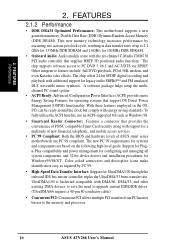
... and Applications are located on the Main Program menu using the Windows Start button: 92 ASUS A7V266 User's Manual Installing the programs enables the multi-channel audio feature. The Speaker menu offers various configurations for this setup. 6.3.1 The C-Media Audio Mixer 1. Note: You must use 4 or 6 channel speakers for your new speaker system. LiveUpdate...
... and Applications are located on the Main Program menu using the Windows Start button: 92 ASUS A7V266 User's Manual Installing the programs enables the multi-channel audio feature. The Speaker menu offers various configurations for this setup. 6.3.1 The C-Media Audio Mixer 1. Note: You must use 4 or 6 channel speakers for your new speaker system. LiveUpdate...

Motherboard DIY Troubleshooting Guide
Page 93
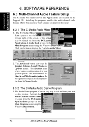
SOFTWARE REFERENCE 2. ASUS A7V266 User's Manual 93 The PCI Multi-Channel Audio Demo has several pages of instructions and hardware diagrams to fine tune the output signals. The Speaker Channel Configuration Menu displays all the options available to help tune the multichannel audio system even more precisely. 6.3.3 ...Rear Speaker Out Rear Speaker Out Pink Mic In Mic In Center Speaker Out, Sub-woofer Note: See 7 in the 6-Channel audio system. To activate the Speaker Channel Configuration Menu, point your PC speaker system. The Help menu features several Demos to help ...
SOFTWARE REFERENCE 2. ASUS A7V266 User's Manual 93 The PCI Multi-Channel Audio Demo has several pages of instructions and hardware diagrams to fine tune the output signals. The Speaker Channel Configuration Menu displays all the options available to help tune the multichannel audio system even more precisely. 6.3.3 ...Rear Speaker Out Rear Speaker Out Pink Mic In Mic In Center Speaker Out, Sub-woofer Note: See 7 in the 6-Channel audio system. To activate the Speaker Channel Configuration Menu, point your PC speaker system. The Help menu features several Demos to help ...

Motherboard DIY Troubleshooting Guide
Page 97
..., CD and MP3 files as well. CD Mode Shuffle Forward Scan Step Frame Next Play Increase Volume Mute Decrease Volume Karaoke Next angle Next audio stream Next subtitle Add bookmark Capture frame Go-Up Repeat Menu Go to Programs, and then CyberLink PowerPlayer SE, and then click PowerPlayer. 6.6.2 CyberLink... to waste time identifying your file types. 6.6.1 Starting CyberLink PowerPlayer SE To start CyberLink Power Player, click the Windows Start button, point to bookmark ASUS A7V266 User's Manual 97 No need for all kinds of video and audio files. 6. S/W REFERENCE Cyberlink 6.
..., CD and MP3 files as well. CD Mode Shuffle Forward Scan Step Frame Next Play Increase Volume Mute Decrease Volume Karaoke Next angle Next audio stream Next subtitle Add bookmark Capture frame Go-Up Repeat Menu Go to Programs, and then CyberLink PowerPlayer SE, and then click PowerPlayer. 6.6.2 CyberLink... to waste time identifying your file types. 6.6.1 Starting CyberLink PowerPlayer SE To start CyberLink Power Player, click the Windows Start button, point to bookmark ASUS A7V266 User's Manual 97 No need for all kinds of video and audio files. 6. S/W REFERENCE Cyberlink 6.

