Motherboard DIY Troubleshooting Guide
Page 1
® A7V-E JumperFree™ PC133/VC133 200MHz FSB AGP 4X Socket A Motherboard USER'S MANUAL
® A7V-E JumperFree™ PC133/VC133 200MHz FSB AGP 4X Socket A Motherboard USER'S MANUAL
Motherboard DIY Troubleshooting Guide
Page 4
... Program 44 4.2.1 BIOS Menu Bar 45 4.2.2 Legend Bar 45 4.3 Main Menu 47 4.3.1 Primary & Secondary Master/Slave 48 4 ASUS A7V-E User's Manual FEATURES 8 2.1 The ASUS A7V-E 8 2.1.1 Specifications 8 2.1.2 Special Features 10 2.1.3 Optional Components 10 2.1.4 Performance Features 10 2.1.5 Intelligence 11 2.2 Motherboard Components 12 2.2.1 Component Locations 13 3. CONTENTS 1. INTRODUCTION 7 1.1 How This Manual Is Organized 7 1.2 Item Checklist 7 2. HARDWARE SETUP 14...
... Program 44 4.2.1 BIOS Menu Bar 45 4.2.2 Legend Bar 45 4.3 Main Menu 47 4.3.1 Primary & Secondary Master/Slave 48 4 ASUS A7V-E User's Manual FEATURES 8 2.1 The ASUS A7V-E 8 2.1.1 Specifications 8 2.1.2 Special Features 10 2.1.3 Optional Components 10 2.1.4 Performance Features 10 2.1.5 Intelligence 11 2.2 Motherboard Components 12 2.2.1 Component Locations 13 3. CONTENTS 1. INTRODUCTION 7 1.1 How This Manual Is Organized 7 1.2 Item Checklist 7 2. HARDWARE SETUP 14...
Motherboard DIY Troubleshooting Guide
Page 5
... 6.2 CyberLink PowerPlayer SE 85 6.4 CyberLink VideoLive Mail 86 7. SOFTWARE SETUP 75 5.1 Install Operating System 75 5.2 Start Windows 75 5.3 A7V-E Series Motherboard Support CD 76 6. APPENDIX 89 7.1 PCI-L101 Fast Ethernet Card 89 7.2 Glossary 91 ASUS A7V-E User's Manual 5 CONTENTS 4.3.2 Keyboard Features 51 4.4 Advanced Menu 53 4.4.1 Chip Configuration 56 4.4.2 I/O Device Configuration 59 4.4.3 PCI Configuration 62...
... 6.2 CyberLink PowerPlayer SE 85 6.4 CyberLink VideoLive Mail 86 7. SOFTWARE SETUP 75 5.1 Install Operating System 75 5.2 Start Windows 75 5.3 A7V-E Series Motherboard Support CD 76 6. APPENDIX 89 7.1 PCI-L101 Fast Ethernet Card 89 7.2 Glossary 91 ASUS A7V-E User's Manual 5 CONTENTS 4.3.2 Keyboard Features 51 4.4 Advanced Menu 53 4.4.1 Chip Configuration 56 4.4.2 I/O Device Configuration 59 4.4.3 PCI Configuration 62...
Motherboard DIY Troubleshooting Guide
Page 7
... disk drives Optional Items ASUS CIDB chassis intrusion detection module ASUS IrDA-compliant infrared module ASUS PCI-L101 Wake-On-LAN 10/ 100 Ethernet Card (1) ASUS 2-port USB Connector Set (1) Bag of spare jumper caps (1) ASUS Support CD with drivers and utilities (1) This Motherboard User's Manual ASUS A7V-E User's Manual 7 SOFTWARE SETUP 6. Package Contents (1) ASUS Motherboard (1) 40-pin 80-conductor...
... disk drives Optional Items ASUS CIDB chassis intrusion detection module ASUS IrDA-compliant infrared module ASUS PCI-L101 Wake-On-LAN 10/ 100 Ethernet Card (1) ASUS 2-port USB Connector Set (1) Bag of spare jumper caps (1) ASUS Support CD with drivers and utilities (1) This Motherboard User's Manual ASUS A7V-E User's Manual 7 SOFTWARE SETUP 6. Package Contents (1) ASUS Motherboard (1) 40-pin 80-conductor...
Motherboard DIY Troubleshooting Guide
Page 8
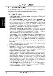
...JumperFree™ mode is a new DRAM core architecture that support four ATA devices on two channels. FEATURES 2.1 The ASUS A7V-E The ASUS A7V-E motherboard is optimized to 100MB/sec; and PCI 2.2. It is carefully designed for the demanding PC user who wants advanced features... among others, high multimedia requirements. • Stepless Frequency Selection: Allows CPU external (FSB) frequency settings to 1GB. Appendix). 8 ASUS A7V-E User's Manual Easy-to-use DIP switches instead of jumpers are included to allow manual adjustment of the processor's external frequency. •...
...JumperFree™ mode is a new DRAM core architecture that support four ATA devices on two channels. FEATURES 2.1 The ASUS A7V-E The ASUS A7V-E motherboard is optimized to 100MB/sec; and PCI 2.2. It is carefully designed for the demanding PC user who wants advanced features... among others, high multimedia requirements. • Stepless Frequency Selection: Allows CPU external (FSB) frequency settings to 1GB. Appendix). 8 ASUS A7V-E User's Manual Easy-to-use DIP switches instead of jumpers are included to allow manual adjustment of the processor's external frequency. •...
Motherboard DIY Troubleshooting Guide
Page 9
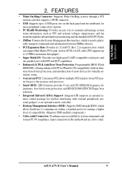
FEA TURES Specifications 2. ASUS A7V-E User's Manual 9 2. FEATURES • Wake-On-Ring Connector: Supports Wake-On-Ring activity through a PCI modem card that ...system status information, such as CPU and systerm voltages, temperatures, and fan status through the onboard hardware monitoring and the bundled ASUS PC Probe. • SMBus: Features the System Management Bus interface, which is used to physically transport commands and information between ...: To enhance user accessibility to system components and to meet PC 99 compliancy, major connectors in this motherboard are color-coded.
FEA TURES Specifications 2. ASUS A7V-E User's Manual 9 2. FEATURES • Wake-On-Ring Connector: Supports Wake-On-Ring activity through a PCI modem card that ...system status information, such as CPU and systerm voltages, temperatures, and fan status through the onboard hardware monitoring and the bundled ASUS PC Probe. • SMBus: Features the System Management Bus interface, which is used to physically transport commands and information between ...: To enhance user accessibility to system components and to meet PC 99 compliancy, major connectors in this motherboard are color-coded.
Motherboard DIY Troubleshooting Guide
Page 10
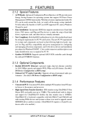
...to the memory and processor. • High-Speed Data Transfer Interface: IDE transfers using UltraDMA/33 Bus Master IDE can be enabled.) 10 ASUS A7V-E User's Manual With these features implemented in BIOS setup). 2.1.4 Performance Features • Concurrent PCI: Concurrent PCI allows multiple PCI transfers from ... around the clock, yet satisfy all system components, and 32-bit device drivers and installation procedures for PC 99 certification. This motherboard with existing DMA devices and systems so there is backward compatible with both DMA/33 and DMA/66 and with its chipset and...
...to the memory and processor. • High-Speed Data Transfer Interface: IDE transfers using UltraDMA/33 Bus Master IDE can be enabled.) 10 ASUS A7V-E User's Manual With these features implemented in BIOS setup). 2.1.4 Performance Features • Concurrent PCI: Concurrent PCI allows multiple PCI transfers from ... around the clock, yet satisfy all system components, and 32-bit device drivers and installation procedures for PC 99 certification. This motherboard with existing DMA devices and systems so there is backward compatible with both DMA/33 and DMA/66 and with its chipset and...
Motherboard DIY Troubleshooting Guide
Page 11
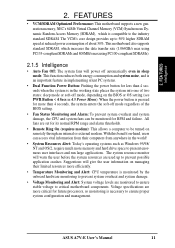
... and system damage. • Voltage Monitoring and Alert: System voltage levels are more efficiently. • Temperature Monitoring and Alert: CPU temperature is compatible to critical motherboard components. With this benefit on managing their computers from their limited resources more critical for RPM and failure. Suggestions will give the user information on... interfaces and run large applications. The system resource monitor will power off mode, depending on remotely through an internal or external modem. FEA TURES Intelligence 2. ASUS A7V-E User's Manual 11
... and system damage. • Voltage Monitoring and Alert: System voltage levels are more efficiently. • Temperature Monitoring and Alert: CPU temperature is compatible to critical motherboard components. With this benefit on managing their computers from their limited resources more critical for RPM and failure. Suggestions will give the user information on... interfaces and run large applications. The system resource monitor will power off mode, depending on remotely through an internal or external modem. FEA TURES Intelligence 2. ASUS A7V-E User's Manual 11
Motherboard DIY Troubleshooting Guide
Page 12
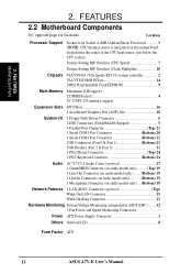
... See opposite page for Socket A AMD Athlon/Duron Processors 3 (NOTE: CPU thermal sensor is integrated on the motherboard, located near the center of the CPU heat source, just below the CPU socket) Feature Setting DIP Switches (CPU Speed 7 Feature Setting DIP Switches (...19 Network Features 1 LAN (RJ45) Connector (optional Top) Wake-On-LAN Connector 15 Wake-On-Ring Connector 13 Hardware Monitoring System Voltage Monitoring (integrated in ASUS ASIC) ....... 12 3 Fan Power and Speed Monitoring Connectors Power ATX Power Supply Connector 1 Others Onboard LED 8 Form Factor ATX 12...
... See opposite page for Socket A AMD Athlon/Duron Processors 3 (NOTE: CPU thermal sensor is integrated on the motherboard, located near the center of the CPU heat source, just below the CPU socket) Feature Setting DIP Switches (CPU Speed 7 Feature Setting DIP Switches (...19 Network Features 1 LAN (RJ45) Connector (optional Top) Wake-On-LAN Connector 15 Wake-On-Ring Connector 13 Hardware Monitoring System Voltage Monitoring (integrated in ASUS ASIC) ....... 12 3 Fan Power and Speed Monitoring Connectors Power ATX Power Supply Connector 1 Others Onboard LED 8 Form Factor ATX 12...
Motherboard DIY Troubleshooting Guide
Page 13
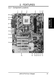
FEA TURES Motherboard Parts 2. FEATURES 2.2.1 Component Locations 1 2 3 4 24 23 22 21 20 19 18 DSFID 5 17 16 5 67 - 15 14 13 121110 9 8 ASUS A7V-E User's Manual 13 2.
FEA TURES Motherboard Parts 2. FEATURES 2.2.1 Component Locations 1 2 3 4 24 23 22 21 20 19 18 DSFID 5 17 16 5 67 - 15 14 13 121110 9 8 ASUS A7V-E User's Manual 13 2.
Motherboard DIY Troubleshooting Guide
Page 14
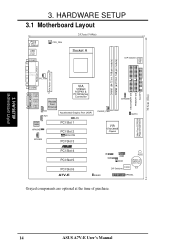
HARDWARE SETUP 3.1 Motherboard Layout PS/2 T: Mouse B: Keyboard USB T: Port0 B: Port1 COM1 CPU_FAN 24.5cm (9.64in) Socket A 01 01 DIP Switches CLOCK TABLE DIMM1 (64/72 bit, 168-pin ... Flash EEPROM (Programmable BIOS) ® PCI Slot 4 PCI Slot 5 PCI Slot 6 IR SMB USB2 WOR PLED CR2032 3V Lithium Cell CMOS Power DSFID DIP Switches A7V-E IDELED HPANEL Grayed components are optional at the time of purchase. 14 ASUS A7V-E User's Manual SECONDARY IDE PRIMARY IDE FLOPPY 30.6cm (12in) 3. H/W SETUP Motherboard Layout 3.
HARDWARE SETUP 3.1 Motherboard Layout PS/2 T: Mouse B: Keyboard USB T: Port0 B: Port1 COM1 CPU_FAN 24.5cm (9.64in) Socket A 01 01 DIP Switches CLOCK TABLE DIMM1 (64/72 bit, 168-pin ... Flash EEPROM (Programmable BIOS) ® PCI Slot 4 PCI Slot 5 PCI Slot 6 IR SMB USB2 WOR PLED CR2032 3V Lithium Cell CMOS Power DSFID DIP Switches A7V-E IDELED HPANEL Grayed components are optional at the time of purchase. 14 ASUS A7V-E User's Manual SECONDARY IDE PRIMARY IDE FLOPPY 30.6cm (12in) 3. H/W SETUP Motherboard Layout 3.
Motherboard DIY Troubleshooting Guide
Page 15
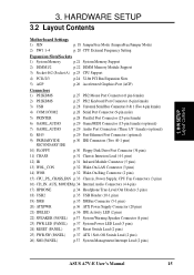
3. H/W SETUP Layout Contents 3. HARDWARE SETUP 3.2 Layout Contents Motherboard Settings 1) JEN p. 18 JumperFree Mode (JumperFree/Jumper Mode) 2) SW1 1-4 p. 20 CPU External Frequency Setting Expansion Slots/Sockets 1) System Memory p.21 System Memory Support 2) DIMM1/2 p.22 ...) p.37 Reset Switch Lead (2 pins) 25) PWR.SW (PANEL) p.37 ATX / Soft-Off Switch Lead (2 pins) 26) SMI (PANEL) p.37 System Management Interrupt Lead (2 pins) ASUS A7V-E User's Manual 15
3. H/W SETUP Layout Contents 3. HARDWARE SETUP 3.2 Layout Contents Motherboard Settings 1) JEN p. 18 JumperFree Mode (JumperFree/Jumper Mode) 2) SW1 1-4 p. 20 CPU External Frequency Setting Expansion Slots/Sockets 1) System Memory p.21 System Memory Support 2) DIMM1/2 p.22 ...) p.37 Reset Switch Lead (2 pins) 25) PWR.SW (PANEL) p.37 ATX / Soft-Off Switch Lead (2 pins) 26) SMI (PANEL) p.37 System Management Interrupt Lead (2 pins) ASUS A7V-E User's Manual 15
Motherboard DIY Troubleshooting Guide
Page 16
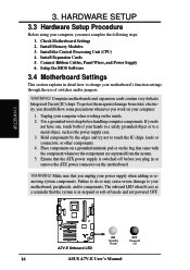
... both of your hands to a safely grounded object or to change your computer. 1. H/W SETUP 01 01 ® A7V-E A7V-E Onboard LED ON Standby Power OFF Powered Off 16 ASUS A7V-E User's Manual Install Expansion Cards 5. Computer motherboards and expansion cards contain very delicate Integrated Circuit (IC) chips. Make sure that the system is switched off...
... both of your hands to a safely grounded object or to change your computer. 1. H/W SETUP 01 01 ® A7V-E A7V-E Onboard LED ON Standby Power OFF Powered Off 16 ASUS A7V-E User's Manual Install Expansion Cards 5. Computer motherboards and expansion cards contain very delicate Integrated Circuit (IC) chips. Make sure that the system is switched off...
Motherboard DIY Troubleshooting Guide
Page 17
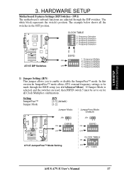
...Default) JEN 12 DSFID ON ON OFF 1 2345 ® A7V-E A7V-E JumperFree™ Mode Setting JEN 23 DSFID ON ON OFF 1 2345 CLOCK TABLE ON ON OFF 1234 5 CPU 100MHz ASUS A7V-E User's Manual 17 SW1) The motherboard's onboard functions are used, then DSFID switch 5 must be made... through the DIP switches. Frequency Selection 1234 5 ON OFF ON 01 01 01 01 ® A7V-E A7V-E DIP Switches DSFID ON ON 1. Frequency ...
...Default) JEN 12 DSFID ON ON OFF 1 2345 ® A7V-E A7V-E JumperFree™ Mode Setting JEN 23 DSFID ON ON OFF 1 2345 CLOCK TABLE ON ON OFF 1234 5 CPU 100MHz ASUS A7V-E User's Manual 17 SW1) The motherboard's onboard functions are used, then DSFID switch 5 must be made... through the DIP switches. Frequency Selection 1234 5 ON OFF ON 01 01 01 01 ® A7V-E A7V-E DIP Switches DSFID ON ON 1. Frequency ...
Motherboard DIY Troubleshooting Guide
Page 18
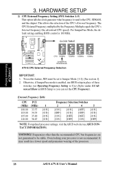
...frequency (the advertised CPU speed). WARNING! Overclocking your processor is 100 MHz. This allows the selection of the processor. 18 ASUS A7V-E User's Manual To use BIOS setup in place of these switches (set the CPU Frequency). It may result in BIOS ...speed and premature wearing of the CPU's External frequency. H/W SETUP Motherboard Settings 3. CLOCK TABLE 01 01 ON 1234 5 ON 1234 5 ON 1234 5 ON 1234 5 CPU 100MHz 103MHz 105MHz 110MHz ® JumperFree A7V-E Mode(Default) A7V-E CPU External Frequency Selection IMPORTANT: 1. For JumperFree Mode, the default...
...frequency (the advertised CPU speed). WARNING! Overclocking your processor is 100 MHz. This allows the selection of the processor. 18 ASUS A7V-E User's Manual To use BIOS setup in place of these switches (set the CPU Frequency). It may result in BIOS ...speed and premature wearing of the CPU's External frequency. H/W SETUP Motherboard Settings 3. CLOCK TABLE 01 01 ON 1234 5 ON 1234 5 ON 1234 5 ON 1234 5 CPU 100MHz 103MHz 105MHz 110MHz ® JumperFree A7V-E Mode(Default) A7V-E CPU External Frequency Selection IMPORTANT: 1. For JumperFree Mode, the default...
Motherboard DIY Troubleshooting Guide
Page 19
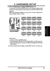
... Multiple (DSFID Switches 1-5) For unlocked CPUs only, the DSFID switches set to date processor settings, visit the ASUS web site: www.asus.com. 3. Switch 5 is locked, setting the Frequency Multiple will have no effect. ® A7V-E A7V-E CPU Core:Bus Frequency Multiple 01 01 ON ON ON ON 1 2345 5.0x ON 1 2345 5.5x ON... Frequencies may also be set the frequency multiple, which determines the relationship between the frequency of your processor is ON for all DSFID settings. 2. H/W SETUP Motherboard Settings ASUS A7V-E User's Manual 19
... Multiple (DSFID Switches 1-5) For unlocked CPUs only, the DSFID switches set to date processor settings, visit the ASUS web site: www.asus.com. 3. Switch 5 is locked, setting the Frequency Multiple will have no effect. ® A7V-E A7V-E CPU Core:Bus Frequency Multiple 01 01 ON ON ON ON 1 2345 5.0x ON 1 2345 5.5x ON... Frequencies may also be set the frequency multiple, which determines the relationship between the frequency of your processor is ON for all DSFID settings. 2. H/W SETUP Motherboard Settings ASUS A7V-E User's Manual 19
Motherboard DIY Troubleshooting Guide
Page 20
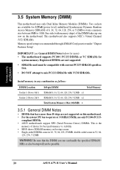
... Memory (DIMM) This motherboard uses only Dual Inline Memory Modules (DIMMs). This motherboard also supports NEC's Virtual Channel (VC) SDRAMs. Memory speed setup is the memory of choice for more than 18 chips are not supported. • SDRAMs used must be possible. 20 ASUS A7V-E User's Manual Registered... DIMMs are not supported on bootup screen. • Single-sided DIMMs come in 32, 64, 128, 256, 512MB. stability. • BIOS shows SDRAM memory on this motherboard. • For the system CPU bus to ...
... Memory (DIMM) This motherboard uses only Dual Inline Memory Modules (DIMMs). This motherboard also supports NEC's Virtual Channel (VC) SDRAMs. Memory speed setup is the memory of choice for more than 18 chips are not supported. • SDRAMs used must be possible. 20 ASUS A7V-E User's Manual Registered... DIMMs are not supported on bootup screen. • Single-sided DIMMs come in 32, 64, 128, 256, 512MB. stability. • BIOS shows SDRAM memory on this motherboard. • For the system CPU bus to ...
Motherboard DIY Troubleshooting Guide
Page 21
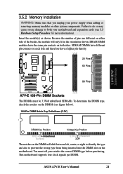
...Key Position Voltage Key Position RFU Unbuffered Buffered 5.0V Reserved 3.3V The notches on the DIMMs (see 3.3 Hardware Setup Procedure for more information). ASUS A7V-E User's Manual 21 You must be 3.3Volt unbuffered SDRAMs. To determine the DIMM type, check the notches on the DIMM will only fit in... 01 3.5.2 Memory Installation WARNING! SDRAM DIMMs have different pin contacts on each side and therefore have the same pin contacts on the motherboard. Failure to do so may cause severe damage to prevent the wrong type from being inserted into the DIMM slot on both your...
...Key Position Voltage Key Position RFU Unbuffered Buffered 5.0V Reserved 3.3V The notches on the DIMMs (see 3.3 Hardware Setup Procedure for more information). ASUS A7V-E User's Manual 21 You must be 3.3Volt unbuffered SDRAMs. To determine the DIMM type, check the notches on the DIMM will only fit in... 01 3.5.2 Memory Installation WARNING! SDRAM DIMMs have different pin contacts on each side and therefore have the same pin contacts on the motherboard. Failure to do so may cause severe damage to prevent the wrong type from being inserted into the DIMM slot on both your...
Motherboard DIY Troubleshooting Guide
Page 23
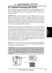
... the slot. H/W SETUP CPU 01 01 ® A7V-E A7V-E Socket A AMD™ Athlon LOCK BLANK LEVER NOTCH ASUS A7V-E User's Manual 23 A CPU thermal sensor is mounted tightly against the processor. To install a CPU, first turn on the motherboard, located near the center of the CPU heat source,...fan and heatsink attached to it to prevent overheating. Without sufficient circulation, the processor could overheat and damage both the processor and the motherboard. Locate the Socket 462 and open it covers the entire face of the four corners, and will be possible. The CPU has...
... the slot. H/W SETUP CPU 01 01 ® A7V-E A7V-E Socket A AMD™ Athlon LOCK BLANK LEVER NOTCH ASUS A7V-E User's Manual 23 A CPU thermal sensor is mounted tightly against the processor. To install a CPU, first turn on the motherboard, located near the center of the CPU heat source,...fan and heatsink attached to it to prevent overheating. Without sufficient circulation, the processor could overheat and damage both the processor and the motherboard. Locate the Socket 462 and open it covers the entire face of the four corners, and will be possible. The CPU has...
Motherboard DIY Troubleshooting Guide
Page 24
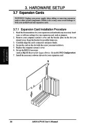
... cause severe damage to use . 3. Set up the BIOS if necessary (such as jumpers. 2. H/W SETUP Expansion Cards 24 ASUS A7V-E User's Manual Unplug your expansion card. 3. Install the necessary software drivers for your motherboard and expansion cards. 3.7.1 Expansion Card Installation Procedure 1. Replace the computer system's cover. 6. Keep the bracket for Legacy Device: Yes...
... cause severe damage to use . 3. Set up the BIOS if necessary (such as jumpers. 2. H/W SETUP Expansion Cards 24 ASUS A7V-E User's Manual Unplug your expansion card. 3. Install the necessary software drivers for your motherboard and expansion cards. 3.7.1 Expansion Card Installation Procedure 1. Replace the computer system's cover. 6. Keep the bracket for Legacy Device: Yes...


