Motherboard DIY Troubleshooting Guide
Page 1
® A7V-E JumperFree™ PC133/VC133 200MHz FSB AGP 4X Socket A Motherboard USER'S MANUAL
® A7V-E JumperFree™ PC133/VC133 200MHz FSB AGP 4X Socket A Motherboard USER'S MANUAL
Motherboard DIY Troubleshooting Guide
Page 4
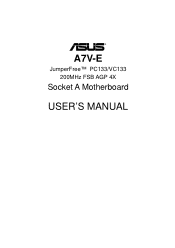
... Expansion Cards 25 3.7.3 Accelerated Graphics Port (AGP 26 3.8 External Connectors 27 3.9 Starting Up the First Time 39 4. FEATURES 8 2.1 The ASUS A7V-E 8 2.1.1 Specifications 8 2.1.2 Special Features 10 2.1.3 Optional Components 10 2.1.4 Performance Features 10 2.1.5 Intelligence 11 2.2 Motherboard Components 12 2.2.1 Component Locations 13 3. BIOS SETUP 41 4.1 Managing and Updating Your BIOS 41 4.1.1 Upon First Use of the...
... Expansion Cards 25 3.7.3 Accelerated Graphics Port (AGP 26 3.8 External Connectors 27 3.9 Starting Up the First Time 39 4. FEATURES 8 2.1 The ASUS A7V-E 8 2.1.1 Specifications 8 2.1.2 Special Features 10 2.1.3 Optional Components 10 2.1.4 Performance Features 10 2.1.5 Intelligence 11 2.2 Motherboard Components 12 2.2.1 Component Locations 13 3. BIOS SETUP 41 4.1 Managing and Updating Your BIOS 41 4.1.1 Upon First Use of the...
Motherboard DIY Troubleshooting Guide
Page 5
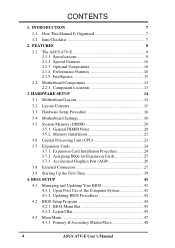
APPENDIX 89 7.1 PCI-L101 Fast Ethernet Card 89 7.2 Glossary 91 ASUS A7V-E User's Manual 5 SOFTWARE REFERENCE 79 6.1 ASUS PC Probe 79 6.3 CyberLink PowerDVD 84 6.2 CyberLink PowerPlayer SE 85 6.4 CyberLink VideoLive Mail 86 7. SOFTWARE SETUP 75 5.1 Install Operating System 75 5.2 Start Windows 75 5.3 A7V-E Series Motherboard Support CD 76 6. CONTENTS 4.3.2 Keyboard Features 51 4.4 Advanced Menu 53 4.4.1 Chip...
APPENDIX 89 7.1 PCI-L101 Fast Ethernet Card 89 7.2 Glossary 91 ASUS A7V-E User's Manual 5 SOFTWARE REFERENCE 79 6.1 ASUS PC Probe 79 6.3 CyberLink PowerDVD 84 6.2 CyberLink PowerPlayer SE 85 6.4 CyberLink VideoLive Mail 86 7. SOFTWARE SETUP 75 5.1 Install Operating System 75 5.2 Start Windows 75 5.3 A7V-E Series Motherboard Support CD 76 6. CONTENTS 4.3.2 Keyboard Features 51 4.4 Advanced Menu 53 4.4.1 Chip...
Motherboard DIY Troubleshooting Guide
Page 7
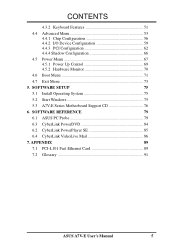
..." and two 3.5" floppy disk drives Optional Items ASUS CIDB chassis intrusion detection module ASUS IrDA-compliant infrared module ASUS PCI-L101 Wake-On-LAN 10/ 100 Ethernet Card (1) ASUS 2-port USB Connector Set (1) Bag of spare jumper caps (1) ASUS Support CD with drivers and utilities (1) This Motherboard User's Manual ASUS A7V-E User's Manual 7 SOFTWARE SETUP 6. INTRODUCTION Manual / Checklist...
..." and two 3.5" floppy disk drives Optional Items ASUS CIDB chassis intrusion detection module ASUS IrDA-compliant infrared module ASUS PCI-L101 Wake-On-LAN 10/ 100 Ethernet Card (1) ASUS 2-port USB Connector Set (1) Bag of spare jumper caps (1) ASUS Support CD with drivers and utilities (1) This Motherboard User's Manual ASUS A7V-E User's Manual 7 SOFTWARE SETUP 6. INTRODUCTION Manual / Checklist...
Motherboard DIY Troubleshooting Guide
Page 8
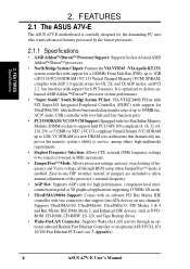
FEATURES 2.1 The ASUS A7V-E The ASUS A7V-E motherboard is a new DRAM core architecture that support four ATA ...adjustment of frequency and Vcore voltage all through an optional onboard Realtek Fast Ethernet Controller or an optional ASUS PCI-L101 10/100 Fast Ethernet PCI card (see 7. bus interface with two Dual Inline Memory Module...ports. • PC133 SDRAM / VC133 VCM Support: Equipped with support for a 200MHz Front Side Bus (FSB); Appendix). 8 ASUS A7V-E User's Manual complies with support for 4X, 2X, and 1X AGP modes; FEA TURES Specifications 2. It is enabled. 2. ...
FEATURES 2.1 The ASUS A7V-E The ASUS A7V-E motherboard is a new DRAM core architecture that support four ATA ...adjustment of frequency and Vcore voltage all through an optional onboard Realtek Fast Ethernet Controller or an optional ASUS PCI-L101 10/100 Fast Ethernet PCI card (see 7. bus interface with two Dual Inline Memory Module...ports. • PC133 SDRAM / VC133 VCM Support: Equipped with support for a 200MHz Front Side Bus (FSB); Appendix). 8 ASUS A7V-E User's Manual complies with support for 4X, 2X, and 1X AGP modes; FEA TURES Specifications 2. It is enabled. 2. ...
Motherboard DIY Troubleshooting Guide
Page 9
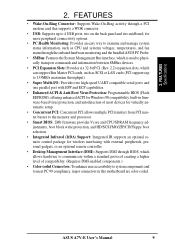
... to examine and manage system status information, such as CPU and systerm voltages, temperatures, and fan status through the onboard hardware monitoring and the bundled ASUS PC Probe. • SMBus: Features the System Management Bus interface, which is used to physically transport commands and information between SMBus devices. •... DMI-enabled components.) • Color-coded Connectors: To enhance user accessibility to system components and to meet PC 99 compliancy, major connectors in this motherboard are color-coded. ASUS A7V-E User's Manual 9 FEA TURES Specifications 2.
... to examine and manage system status information, such as CPU and systerm voltages, temperatures, and fan status through the onboard hardware monitoring and the bundled ASUS PC Probe. • SMBus: Features the System Management Bus interface, which is used to physically transport commands and information between SMBus devices. •... DMI-enabled components.) • Color-coded Connectors: To enhance user accessibility to system components and to meet PC 99 compliancy, major connectors in this motherboard are color-coded. ASUS A7V-E User's Manual 9 FEA TURES Specifications 2.
Motherboard DIY Troubleshooting Guide
Page 10
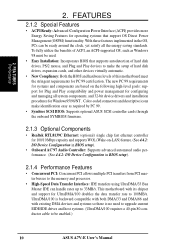
... 32-bit device drivers and installation procedures for configuring and managing all the energy saving standards. This motherboard with existing DMA devices and systems so there is backward compatible with both DMA/33 and DMA/66... cards, and other devices virtually automatic. • New Compliancy: Both the BIOS and hardware levels of this motherboard meet the stringent requirements for operating systems that supports autodetection of ACPI, an ACPI-supported OS, such as required... rates up to make identification easy as Windows 98 must be enabled.) 10 ASUS A7V-E User's Manual 2.
... 32-bit device drivers and installation procedures for configuring and managing all the energy saving standards. This motherboard with existing DMA devices and systems so there is backward compatible with both DMA/33 and DMA/66... cards, and other devices virtually automatic. • New Compliancy: Both the BIOS and hardware levels of this motherboard meet the stringent requirements for operating systems that supports autodetection of ACPI, an ACPI-supported OS, such as required... rates up to make identification easy as Windows 98 must be enabled.) 10 ASUS A7V-E User's Manual 2.
Motherboard DIY Troubleshooting Guide
Page 11
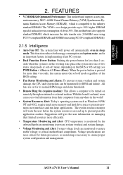
... 2. Voltage specifications are used up to prevent possible application crashes. FEA TURES Intelligence 2. FEATURES • VCM/SDRAM Optimized Performance: This motherboard supports a new generation memory, NEC's 64Mb Virtual Channel Memory (VCM) Synchronous Dynamic Random Access Memory (SDRAM), which increases the data ...will warn the user before the system resources are more than 4 seconds when the system is pressed for RPM and failure. ASUS A7V-E User's Manual 11 The VCM's core design provides up to 50% higher SDRAM speed at reduced power consumption of the BIOS...
... 2. Voltage specifications are used up to prevent possible application crashes. FEA TURES Intelligence 2. FEATURES • VCM/SDRAM Optimized Performance: This motherboard supports a new generation memory, NEC's 64Mb Virtual Channel Memory (VCM) Synchronous Dynamic Random Access Memory (SDRAM), which increases the data ...will warn the user before the system resources are more than 4 seconds when the system is pressed for RPM and failure. ASUS A7V-E User's Manual 11 The VCM's core design provides up to 50% higher SDRAM speed at reduced power consumption of the BIOS...
Motherboard DIY Troubleshooting Guide
Page 12
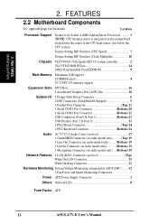
... See opposite page for Socket A AMD Athlon/Duron Processors 3 (NOTE: CPU thermal sensor is integrated on the motherboard, located near the center of the CPU heat source, just below the CPU socket) Feature Setting DIP Switches (CPU Speed 7 Feature Setting DIP Switches (...19 Network Features 1 LAN (RJ45) Connector (optional Top) Wake-On-LAN Connector 15 Wake-On-Ring Connector 13 Hardware Monitoring System Voltage Monitoring (integrated in ASUS ASIC) ....... 12 3 Fan Power and Speed Monitoring Connectors Power ATX Power Supply Connector 1 Others Onboard LED 8 Form Factor ATX 12...
... See opposite page for Socket A AMD Athlon/Duron Processors 3 (NOTE: CPU thermal sensor is integrated on the motherboard, located near the center of the CPU heat source, just below the CPU socket) Feature Setting DIP Switches (CPU Speed 7 Feature Setting DIP Switches (...19 Network Features 1 LAN (RJ45) Connector (optional Top) Wake-On-LAN Connector 15 Wake-On-Ring Connector 13 Hardware Monitoring System Voltage Monitoring (integrated in ASUS ASIC) ....... 12 3 Fan Power and Speed Monitoring Connectors Power ATX Power Supply Connector 1 Others Onboard LED 8 Form Factor ATX 12...
Motherboard DIY Troubleshooting Guide
Page 13
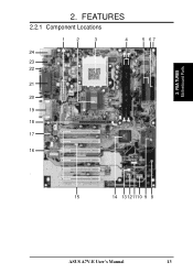
2. FEATURES 2.2.1 Component Locations 1 2 3 4 24 23 22 21 20 19 18 DSFID 5 17 16 5 67 - 15 14 13 121110 9 8 ASUS A7V-E User's Manual 13 FEA TURES Motherboard Parts 2.
2. FEATURES 2.2.1 Component Locations 1 2 3 4 24 23 22 21 20 19 18 DSFID 5 17 16 5 67 - 15 14 13 121110 9 8 ASUS A7V-E User's Manual 13 FEA TURES Motherboard Parts 2.
Motherboard DIY Troubleshooting Guide
Page 14
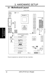
SECONDARY IDE PRIMARY IDE FLOPPY 30.6cm (12in) 3. H/W SETUP Motherboard Layout 3. HARDWARE SETUP 3.1 Motherboard Layout PS/2 T: Mouse B: Keyboard USB T: Port0 B: Port1 COM1 CPU_FAN 24.5cm (9.64in) Socket A 01 01 DIP Switches CLOCK TABLE DIMM1 (64/72 bit, 168-pin ... Flash EEPROM (Programmable BIOS) ® PCI Slot 4 PCI Slot 5 PCI Slot 6 IR SMB USB2 WOR PLED CR2032 3V Lithium Cell CMOS Power DSFID DIP Switches A7V-E IDELED HPANEL Grayed components are optional at the time of purchase. 14...
SECONDARY IDE PRIMARY IDE FLOPPY 30.6cm (12in) 3. H/W SETUP Motherboard Layout 3. HARDWARE SETUP 3.1 Motherboard Layout PS/2 T: Mouse B: Keyboard USB T: Port0 B: Port1 COM1 CPU_FAN 24.5cm (9.64in) Socket A 01 01 DIP Switches CLOCK TABLE DIMM1 (64/72 bit, 168-pin ... Flash EEPROM (Programmable BIOS) ® PCI Slot 4 PCI Slot 5 PCI Slot 6 IR SMB USB2 WOR PLED CR2032 3V Lithium Cell CMOS Power DSFID DIP Switches A7V-E IDELED HPANEL Grayed components are optional at the time of purchase. 14...
Motherboard DIY Troubleshooting Guide
Page 15
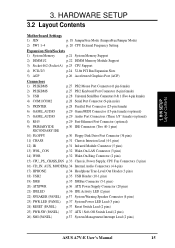
HARDWARE SETUP 3.2 Layout Contents Motherboard Settings 1) JEN p. 18 JumperFree Mode (JumperFree/Jumper Mode) 2) SW1 1-4 p. 20 CPU External Frequency Setting Expansion Slots/Sockets 1) System Memory p.21 System Memory Support 2) DIMM1/2 p.22 ...) p.37 Reset Switch Lead (2 pins) 25) PWR.SW (PANEL) p.37 ATX / Soft-Off Switch Lead (2 pins) 26) SMI (PANEL) p.37 System Management Interrupt Lead (2 pins) ASUS A7V-E User's Manual 15 3. H/W SETUP Layout Contents 3.
HARDWARE SETUP 3.2 Layout Contents Motherboard Settings 1) JEN p. 18 JumperFree Mode (JumperFree/Jumper Mode) 2) SW1 1-4 p. 20 CPU External Frequency Setting Expansion Slots/Sockets 1) System Memory p.21 System Memory Support 2) DIMM1/2 p.22 ...) p.37 Reset Switch Lead (2 pins) 25) PWR.SW (PANEL) p.37 ATX / Soft-Off Switch Lead (2 pins) 26) SMI (PANEL) p.37 System Management Interrupt Lead (2 pins) ASUS A7V-E User's Manual 15 3. H/W SETUP Layout Contents 3.
Motherboard DIY Troubleshooting Guide
Page 16
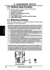
...when lit acts as the power supply case. 3. Install the Central Processing Unit (CPU) 4. Setup the BIOS Software 3.4 Motherboard Settings This section explains in suspend or soft-off before handling computer components. HARDWARE SETUP 3.3 Hardware Setup Procedure Before using ...WARNING! Place components on a grounded antistatic pad or on your motherboard's function settings through the use of your computer when working on the motherboard. Install Expansion Cards 5. H/W SETUP 01 01 ® A7V-E A7V-E Onboard LED ON Standby Power OFF Powered Off 16 ASUS A7V-E User's Manual
...when lit acts as the power supply case. 3. Install the Central Processing Unit (CPU) 4. Setup the BIOS Software 3.4 Motherboard Settings This section explains in suspend or soft-off before handling computer components. HARDWARE SETUP 3.3 Hardware Setup Procedure Before using ...WARNING! Place components on a grounded antistatic pad or on your motherboard's function settings through the use of your computer when working on the motherboard. Install Expansion Cards 5. H/W SETUP 01 01 ® A7V-E A7V-E Onboard LED ON Standby Power OFF Powered Off 16 ASUS A7V-E User's Manual
Motherboard DIY Troubleshooting Guide
Page 17
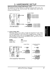
...JumperFree Mode (Default) JEN 12 DSFID ON ON OFF 1 2345 ® A7V-E A7V-E JumperFree™ Mode Setting JEN 23 DSFID ON ON OFF 1 2345 CLOCK TABLE ON ON OFF 1234 5 CPU 100MHz ASUS A7V-E User's Manual 17 CLOCK TABLE 5. Frequency Selection 1. If Jumper Mode is ...selected, and the switches are adjusted through the BIOS setup (see 4.4 Advanced Menu). SW1) The motherboard's onboard functions are used, then DSFID switch...
...JumperFree Mode (Default) JEN 12 DSFID ON ON OFF 1 2345 ® A7V-E A7V-E JumperFree™ Mode Setting JEN 23 DSFID ON ON OFF 1 2345 CLOCK TABLE ON ON OFF 1234 5 CPU 100MHz ASUS A7V-E User's Manual 17 CLOCK TABLE 5. Frequency Selection 1. If Jumper Mode is ...selected, and the switches are adjusted through the BIOS setup (see 4.4 Advanced Menu). SW1) The motherboard's onboard functions are used, then DSFID switch...
Motherboard DIY Troubleshooting Guide
Page 18
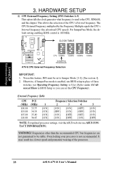
...SDRAM, and the chipset. This allows the selection of the processor. 18 ASUS A7V-E User's Manual CLOCK TABLE 01 01 ON 1234 5 ON 1234 5 ON 1234 5 ON 1234 5 CPU 100MHz 103MHz 105MHz 110MHz ® JumperFree A7V-E Mode(Default) A7V-E CPU External Frequency Selection IMPORTANT: 1. Otherwise, if JumperFree mode is ... frequency (the advertised CPU speed). WARNING! For JumperFree Mode, the default setting enabling BIOS control is not recommended. H/W SETUP Motherboard Settings 3. 3. It may result in BIOS Setup so you can set to Jumper Mode: [1-2]; [See section 1]. 2.
...SDRAM, and the chipset. This allows the selection of the processor. 18 ASUS A7V-E User's Manual CLOCK TABLE 01 01 ON 1234 5 ON 1234 5 ON 1234 5 ON 1234 5 CPU 100MHz 103MHz 105MHz 110MHz ® JumperFree A7V-E Mode(Default) A7V-E CPU External Frequency Selection IMPORTANT: 1. Otherwise, if JumperFree mode is ... frequency (the advertised CPU speed). WARNING! For JumperFree Mode, the default setting enabling BIOS control is not recommended. H/W SETUP Motherboard Settings 3. 3. It may result in BIOS Setup so you can set to Jumper Mode: [1-2]; [See section 1]. 2.
Motherboard DIY Troubleshooting Guide
Page 19
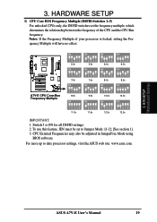
... SETUP 3) CPU Core BUS Frequency Multiple (DSFID Switches 1-5) For unlocked CPUs only, the DSFID switches set to date processor settings, visit the ASUS web site: www.asus.com. 3. H/W SETUP Motherboard Settings ASUS A7V-E User's Manual 19 CPU External Frequencies may also be set the frequency multiple, which determines the relationship between the frequency of your...
... SETUP 3) CPU Core BUS Frequency Multiple (DSFID Switches 1-5) For unlocked CPUs only, the DSFID switches set to date processor settings, visit the ASUS web site: www.asus.com. 3. H/W SETUP Motherboard Settings ASUS A7V-E User's Manual 19 CPU External Frequencies may also be set the frequency multiple, which determines the relationship between the frequency of your...
Motherboard DIY Troubleshooting Guide
Page 20
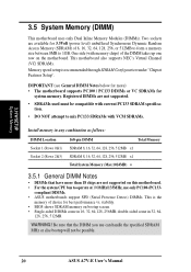
Registered DIMMs are not supported. • SDRAMs used must be possible. 20 ASUS A7V-E User's Manual WARNING! H/W SETUP System Memory 3.5 System Memory (DIMM) This motherboard uses only Dual Inline Memory Modules (DIMMs). One side (with VCM SDRAMs. Install memory in any combination as follows:...come in 32, 64, 128, 256, 512MB. compliant DIMMs. • ASUS motherboards support SPD (Serial Presence Detect) DIMMs. This is recommended through SDRAM Configuration under "Chipset Features Setup". This motherboard also supports NEC's Virtual Channel (VC) SDRAMs. Memory speed setup is the...
Registered DIMMs are not supported. • SDRAMs used must be possible. 20 ASUS A7V-E User's Manual WARNING! H/W SETUP System Memory 3.5 System Memory (DIMM) This motherboard uses only Dual Inline Memory Modules (DIMMs). One side (with VCM SDRAMs. Install memory in any combination as follows:...come in 32, 64, 128, 256, 512MB. compliant DIMMs. • ASUS motherboards support SPD (Serial Presence Detect) DIMMs. This is recommended through SDRAM Configuration under "Chipset Features Setup". This motherboard also supports NEC's Virtual Channel (VC) SDRAMs. Memory speed setup is the...
Motherboard DIY Troubleshooting Guide
Page 21
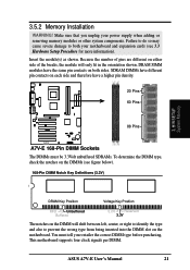
... Insert the module(s) as shown. SDRAM DIMMs have different pin contacts on each side and therefore have the same pin contacts on the motherboard. H/W SETUP System Memory DRAM Key Position Voltage Key Position RFU Unbuffered Buffered 5.0V Reserved 3.3V The notches on the DIMM will only... fit in the orientation shown. 01 01 3.5.2 Memory Installation WARNING! ASUS A7V-E User's Manual 21 DRAM SIMM modules have a higher pin density. 20 Pins 60 Pins 88 Pins ® A7V-E A7V-E 168-Pin DIMM Sockets The DIMMs must tell your retailer the correct DIMM type before...
... Insert the module(s) as shown. SDRAM DIMMs have different pin contacts on each side and therefore have the same pin contacts on the motherboard. H/W SETUP System Memory DRAM Key Position Voltage Key Position RFU Unbuffered Buffered 5.0V Reserved 3.3V The notches on the DIMM will only... fit in the orientation shown. 01 01 3.5.2 Memory Installation WARNING! ASUS A7V-E User's Manual 21 DRAM SIMM modules have a higher pin density. 20 Pins 60 Pins 88 Pins ® A7V-E A7V-E 168-Pin DIMM Sockets The DIMMs must tell your retailer the correct DIMM type before...
Motherboard DIY Troubleshooting Guide
Page 23
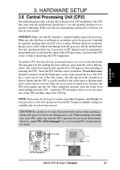
... not bent. CAUTION! H/W SETUP CPU 01 01 ® A7V-E A7V-E Socket A AMD™ Athlon LOCK BLANK LEVER NOTCH ASUS A7V-E User's Manual 23 Make sure also that the CPU capacitors do not forget to help in the orientation as shown. Insert the CPU with the motherboard should be possible. HARDWARE SETUP 3.6 Central Processing Unit (CPU...
... not bent. CAUTION! H/W SETUP CPU 01 01 ® A7V-E A7V-E Socket A AMD™ Athlon LOCK BLANK LEVER NOTCH ASUS A7V-E User's Manual 23 Make sure also that the CPU capacitors do not forget to help in the orientation as shown. Insert the CPU with the motherboard should be possible. HARDWARE SETUP 3.6 Central Processing Unit (CPU...
Motherboard DIY Troubleshooting Guide
Page 24
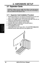
... card and make any necessary hardware or software settings for possible future use . H/W SETUP Expansion Cards 24 ASUS A7V-E User's Manual Failure to do so may cause severe damage to use . 3. Keep the bracket for your motherboard and expansion cards. 3.7.1 Expansion Card Installation Procedure 1. Carefully align the card's connectors and press firmly. 4. 3. Unplug...
... card and make any necessary hardware or software settings for possible future use . H/W SETUP Expansion Cards 24 ASUS A7V-E User's Manual Failure to do so may cause severe damage to use . 3. Keep the bracket for your motherboard and expansion cards. 3.7.1 Expansion Card Installation Procedure 1. Carefully align the card's connectors and press firmly. 4. 3. Unplug...


