Motherboard DIY Troubleshooting Guide
Page 2
Products and corporate names appearing in the manual revision number. For previous or updated manuals, BIOS, drivers, or product release information, contact ASUS at http://www.asus.com.tw or through any of the means indicated on the product itself. or (2) the serial number of the ... INACCURACIES THAT MAY APPEAR IN THIS MANUAL, INCLUDING THE PRODUCTS AND SOFTWARE DESCRIBED IN IT. Product Name: ASUS A7M266 Manual Revision: 1.04 E776 Release Date: May 2001 2 ASUS A7M266 User's Manual USER'S NOTICE No part of this manual may or may not be registered trademarks or copyrights...
Products and corporate names appearing in the manual revision number. For previous or updated manuals, BIOS, drivers, or product release information, contact ASUS at http://www.asus.com.tw or through any of the means indicated on the product itself. or (2) the serial number of the ... INACCURACIES THAT MAY APPEAR IN THIS MANUAL, INCLUDING THE PRODUCTS AND SOFTWARE DESCRIBED IN IT. Product Name: ASUS A7M266 Manual Revision: 1.04 E776 Release Date: May 2001 2 ASUS A7M266 User's Manual USER'S NOTICE No part of this manual may or may not be registered trademarks or copyrights...
Motherboard DIY Troubleshooting Guide
Page 4
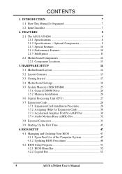
... 4.1.1 Upon First Use of the Computer System 47 4.1.2 Updating BIOS Procedures 48 4.2 BIOS Setup Program 51 4.2.1 BIOS Menu Bar 52 4.2.2 Legend Bar 52 4 ASUS A7M266 User's Manual CONTENTS 1. INTRODUCTION 7 1.1 How This Manual Is Organized 7 1.2 Item Checklist 7 2. ...AMR) Slot 32 3.8 External Connectors 33 3.9 Starting Up the First Time 45 4. FEATURES 8 2.1 The ASUS A7M266 8 2.1.1 Specifications 8 2.1.2 Specifications - Optional Components 9 2.1.3 Special Features 10 2.1.4 Performance Features 10 2.1.5 Intelligence 11 2.2 Motherboard Components 12 2.2.1 Component...
... 4.1.1 Upon First Use of the Computer System 47 4.1.2 Updating BIOS Procedures 48 4.2 BIOS Setup Program 51 4.2.1 BIOS Menu Bar 52 4.2.2 Legend Bar 52 4 ASUS A7M266 User's Manual CONTENTS 1. INTRODUCTION 7 1.1 How This Manual Is Organized 7 1.2 Item Checklist 7 2. ...AMR) Slot 32 3.8 External Connectors 33 3.9 Starting Up the First Time 45 4. FEATURES 8 2.1 The ASUS A7M266 8 2.1.1 Specifications 8 2.1.2 Specifications - Optional Components 9 2.1.3 Special Features 10 2.1.4 Performance Features 10 2.1.5 Intelligence 11 2.2 Motherboard Components 12 2.2.1 Component...

Motherboard DIY Troubleshooting Guide
Page 7
...setting up the motherboard. 4. Package Contents (1) ASUS Motherboard (1) 40-pin 80-conductor ribbon cable for internal UltraDMA/ 100 / UltraDMA/66 (also compatible with drivers and utilities (1) This Motherboard User's Manual ASUS A7M266 User's Manual 7 APPENDIX Optional items and ...general reference 1.2 Item Checklist Check that your retailer. INTRODUCTION Manual information and checklist 2. HARDWARE SETUP Instructions on setting up the BIOS 5. If you discover damaged or...
...setting up the motherboard. 4. Package Contents (1) ASUS Motherboard (1) 40-pin 80-conductor ribbon cable for internal UltraDMA/ 100 / UltraDMA/66 (also compatible with drivers and utilities (1) This Motherboard User's Manual ASUS A7M266 User's Manual 7 APPENDIX Optional items and ...general reference 1.2 Item Checklist Check that your retailer. INTRODUCTION Manual information and checklist 2. HARDWARE SETUP Instructions on setting up the BIOS 5. If you discover damaged or...

Motherboard DIY Troubleshooting Guide
Page 8
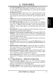
... requirements. • Stepless Frequency Selection: Allows CPU external (FSB) frequency settings to allow manual adjustment of frequency and Vcore voltage all through BIOS setup when JumperFree™ mode is optimized to deliver enhanced AMD Athlon™ processor system performance. • "Super South" South Bridge System... for 4X, 2X and 1X AGP modes and PCI 2.2. bus interface with AGP 2.0 specifications for more peripheral connectivity options. 8 ASUS A7M266 User's Manual Appendix). • Wake-On-Ring Connector: Supports Wake-On-Ring activity through an optional...
... requirements. • Stepless Frequency Selection: Allows CPU external (FSB) frequency settings to allow manual adjustment of frequency and Vcore voltage all through BIOS setup when JumperFree™ mode is optimized to deliver enhanced AMD Athlon™ processor system performance. • "Super South" South Bridge System... for 4X, 2X and 1X AGP modes and PCI 2.2. bus interface with AGP 2.0 specifications for more peripheral connectivity options. 8 ASUS A7M266 User's Manual Appendix). • Wake-On-Ring Connector: Supports Wake-On-Ring activity through an optional...
Motherboard DIY Troubleshooting Guide
Page 9
... and one parallel port with EPP and ECP capabilities. • Enhanced ACPI & Anti-Boot Virus Protection: Programmable BIOS (Flash EEPROM), offering enhanced ACPI for Windows 982000/Millenium compatibility, built-in firmware-based virus protection, and autodetection ...PCI: Concurrent PCI allows multiple PCI transfers from PCI master busses to the memory and processor. • Smart BIOS: 2Mb firmware provides Vcore and CPU/SDRAM frequency adjustments, boot block write protection, and HD/SCSI/MO/ZIP/CD... PCI v2.1 bus controller and legacy SB® DSP audio emulator. ASUS A7M266 User's Manual 9
... and one parallel port with EPP and ECP capabilities. • Enhanced ACPI & Anti-Boot Virus Protection: Programmable BIOS (Flash EEPROM), offering enhanced ACPI for Windows 982000/Millenium compatibility, built-in firmware-based virus protection, and autodetection ...PCI: Concurrent PCI allows multiple PCI transfers from PCI master busses to the memory and processor. • Smart BIOS: 2Mb firmware provides Vcore and CPU/SDRAM frequency adjustments, boot block write protection, and HD/SCSI/MO/ZIP/CD... PCI v2.1 bus controller and legacy SB® DSP audio emulator. ASUS A7M266 User's Manual 9
Motherboard DIY Troubleshooting Guide
Page 10
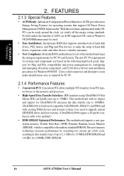
... installation procedures for operating systems that supports autodetection of this motherboard meet the stringent requirements for 100MHz DDR SDRAM. 10 ASUS A7M266 User's Manual UltraDMA/100 is compatible to 33MB/s. FEATURES 2.1.3 Special Features • ACPI Ready: Advanced Configuration Power ... Plug and Play devices to make identification easy as Windows 98/2000/Millenium must be used. • Easy Installation: Incorporates BIOS that support OS Direct Power Management (OSPM) functionality. This new memory technology increases performance by PC 99. 2.1.4 Performance Features ...
... installation procedures for operating systems that supports autodetection of this motherboard meet the stringent requirements for 100MHz DDR SDRAM. 10 ASUS A7M266 User's Manual UltraDMA/100 is compatible to 33MB/s. FEATURES 2.1.3 Special Features • ACPI Ready: Advanced Configuration Power ... Plug and Play devices to make identification easy as Windows 98/2000/Millenium must be used. • Easy Installation: Incorporates BIOS that support OS Direct Power Management (OSPM) functionality. This new memory technology increases performance by PC 99. 2.1.4 Performance Features ...

Motherboard DIY Troubleshooting Guide
Page 11
... seconds when the system is kept in memory on the BIOS or OS setting (see PWR Button < 4 Secs in the world! • System Resources Alert: Today's operating systems such as information providers. ASUS A7M266 User's Manual 11 FEATURES Intelligence 2. All fans are more ...protection. The system resource monitor will give the user information on remotely through the ASUS ASIC. A chassis intrusion event is in the mailbox....
... seconds when the system is kept in memory on the BIOS or OS setting (see PWR Button < 4 Secs in the world! • System Resources Alert: Today's operating systems such as information providers. ASUS A7M266 User's Manual 11 FEATURES Intelligence 2. All fans are more ...protection. The system resource monitor will give the user information on remotely through the ASUS ASIC. A chassis intrusion event is in the mailbox....

Motherboard DIY Troubleshooting Guide
Page 14
PRIMARY IDE SECONDARY IDE 2Mbit Flash EEPROM (Programmable BIOS) 30.6cm (12in) Socket A C-Media CMI-8738 PCI Audio 3. H/W SETUP Motherboard Layout 3. HARDWARE SETUP 3.1 Motherboard Layout PS/2 T: Mouse B: Keyboard USB Top: T: USB1 RJ-45 B: USB2 ... 3 WOLCON PCI Slot 4 VID4 VID3 VID2 VID1 PCI Slot 5 MODEM Audio Modem Riser (AMR) WOR PLED DSCKF A7M266 CR2032 3V Lithium Cell CMOS Power VIA VT82C686B ® PCIset CLRTC JTPWR JEN CHA_FAN USBPORT ASUS USBPWR2 CHASSIS ASIC with Hardware IR Monitor AFPANEL IDELED SMB PANEL Grayed components are available only on certain...
PRIMARY IDE SECONDARY IDE 2Mbit Flash EEPROM (Programmable BIOS) 30.6cm (12in) Socket A C-Media CMI-8738 PCI Audio 3. H/W SETUP Motherboard Layout 3. HARDWARE SETUP 3.1 Motherboard Layout PS/2 T: Mouse B: Keyboard USB Top: T: USB1 RJ-45 B: USB2 ... 3 WOLCON PCI Slot 4 VID4 VID3 VID2 VID1 PCI Slot 5 MODEM Audio Modem Riser (AMR) WOR PLED DSCKF A7M266 CR2032 3V Lithium Cell CMOS Power VIA VT82C686B ® PCIset CLRTC JTPWR JEN CHA_FAN USBPORT ASUS USBPWR2 CHASSIS ASIC with Hardware IR Monitor AFPANEL IDELED SMB PANEL Grayed components are available only on certain...

Motherboard DIY Troubleshooting Guide
Page 17
Connect Ribbon Cables, Panel Wires, and Power Supply 6. Check Motherboard Settings 2. Install the Central Processing Unit (CPU) 4. Setup the BIOS Software 3. Install Memory Modules 3. H/W SETUP Getting Started ASUS A7M266 User's Manual 17 HARDWARE SETUP 3.3 Getting Started Before using your computer, you must complete the following steps: 1. 3. Install Expansion Cards 5.
Connect Ribbon Cables, Panel Wires, and Power Supply 6. Check Motherboard Settings 2. Install the Central Processing Unit (CPU) 4. Setup the BIOS Software 3. Install Memory Modules 3. H/W SETUP Getting Started ASUS A7M266 User's Manual 17 HARDWARE SETUP 3.3 Getting Started Before using your computer, you must complete the following steps: 1. 3. Install Expansion Cards 5.

Motherboard DIY Troubleshooting Guide
Page 19
DSCKF) The motherboard's onboard functions are adjusted through the BIOS setup (see 4.4 Advanced Menu). Frequency Selection 1) JumperFree™ Mode (JEN) This jumper allows you to be set to [3-4]. The example below shows all...Mode Jumper Free (Default) JEN NOTE: In JumperFree™ mode, all the switches in the OFF position. 01 01 01 01 A7M266 ® A7M266 DIP Switch DSCKF ON 1234 OFF ON 1. ASUS A7M266 User's Manual 19 Frequency Selection 2. Frequency Selection 4. The white block represents the switch's position. Frequency Selection 3. 3. HARDWARE SETUP ...
DSCKF) The motherboard's onboard functions are adjusted through the BIOS setup (see 4.4 Advanced Menu). Frequency Selection 1) JumperFree™ Mode (JEN) This jumper allows you to be set to [3-4]. The example below shows all...Mode Jumper Free (Default) JEN NOTE: In JumperFree™ mode, all the switches in the OFF position. 01 01 01 01 A7M266 ® A7M266 DIP Switch DSCKF ON 1234 OFF ON 1. ASUS A7M266 User's Manual 19 Frequency Selection 2. Frequency Selection 4. The white block represents the switch's position. Frequency Selection 3. 3. HARDWARE SETUP ...

Motherboard DIY Troubleshooting Guide
Page 22
... Jumper mode or [1-2]. 2. H/W SETUP Motherboard Settings 22 ASUS A7M266 User's Manual To use BIOS setup in BIOS Setup so you can set the CPU Frequency). DSCKF 01 01 ON 1234 ON 1234 ON 1234 CPU 100MHz 103MHz 105MHz ON 1234 ON 1234 ON 1234 A7M266 ® CPU 110MHz A7M266 CPU External Frequency Selection 115MHz 133MHz WARNING...
... Jumper mode or [1-2]. 2. H/W SETUP Motherboard Settings 22 ASUS A7M266 User's Manual To use BIOS setup in BIOS Setup so you can set the CPU Frequency). DSCKF 01 01 ON 1234 ON 1234 ON 1234 CPU 100MHz 103MHz 105MHz ON 1234 ON 1234 ON 1234 A7M266 ® CPU 110MHz A7M266 CPU External Frequency Selection 115MHz 133MHz WARNING...

Motherboard DIY Troubleshooting Guide
Page 26
... when adding or removing memory modules or other system components. H/W SETUP System Memory 01 01 A7M266 ® A7M266 184-Pin DDR DIMM Sockets This motherboard supports three pairs of center. 3. stability. • BIOS shows SDRAM memory on either side of the breaks, the module will not be possible. 3.5.2...256, and 512MB. A 184-pin DDR SDRAM DIMM has a single notch slightly to the right of differential clock signals per DIMM. 26 ASUS A7M266 User's Manual Failure to do so may cause severe damage to operate at 200MHz/266MHz, use can handle the specified DDR SDRAM MHz or...
... when adding or removing memory modules or other system components. H/W SETUP System Memory 01 01 A7M266 ® A7M266 184-Pin DDR DIMM Sockets This motherboard supports three pairs of center. 3. stability. • BIOS shows SDRAM memory on either side of the breaks, the module will not be possible. 3.5.2...256, and 512MB. A 184-pin DDR SDRAM DIMM has a single notch slightly to the right of differential clock signals per DIMM. 26 ASUS A7M266 User's Manual Failure to do so may cause severe damage to operate at 200MHz/266MHz, use can handle the specified DDR SDRAM MHz or...

Motherboard DIY Troubleshooting Guide
Page 29
...3.7 Expansion Cards WARNING! Read the documentation for your expansion card and make any necessary hardware or software settings for your expansion card. 3. Set up the BIOS if necessary (such as jumpers. 2. Keep the bracket for your expansion card, such as IRQ xx Used By ISA: Yes in 4.4.3 PCI Configuration) 7..... 6. Unplug your motherboard and expansion cards. 3.7.1 Expansion Card Installation Procedure 1. Failure to do so may cause severe damage to use . 3. H/W SETUP Expansion Cards ASUS A7M266 User's Manual 29 Secure the card on the slot you removed above. 5. 3.
...3.7 Expansion Cards WARNING! Read the documentation for your expansion card and make any necessary hardware or software settings for your expansion card. 3. Set up the BIOS if necessary (such as jumpers. 2. Keep the bracket for your expansion card, such as IRQ xx Used By ISA: Yes in 4.4.3 PCI Configuration) 7..... 6. Unplug your motherboard and expansion cards. 3.7.1 Expansion Card Installation Procedure 1. Failure to do so may cause severe damage to use . 3. H/W SETUP Expansion Cards ASUS A7M266 User's Manual 29 Secure the card on the slot you removed above. 5. 3.

Motherboard DIY Troubleshooting Guide
Page 36
...when using ribbon cables with pin 20 plugged). 01 01 01 01 3. H/W SETUP Connectors Primary IDE Connector Secondary IDE Connector A7M266 ® A7M266 IDE Connectors NOTE: Orient the red markings (usually zigzag) on the floppy ribbon cable to your UltraDMA/100 master device....through the BIOS. HARDWARE SETUP 9) Floppy Disk Drive Connector (34-1 pin FLOPPY) This connector supports the provided floppy drive ribbon cable. After connecting the single end to prevent inserting in the wrong orientation when using ribbon cables with pin 5 plugged). PIN 1 36 ASUS A7M266 User's...
...when using ribbon cables with pin 20 plugged). 01 01 01 01 3. H/W SETUP Connectors Primary IDE Connector Secondary IDE Connector A7M266 ® A7M266 IDE Connectors NOTE: Orient the red markings (usually zigzag) on the floppy ribbon cable to your UltraDMA/100 master device....through the BIOS. HARDWARE SETUP 9) Floppy Disk Drive Connector (34-1 pin FLOPPY) This connector supports the provided floppy drive ribbon cable. After connecting the single end to prevent inserting in the wrong orientation when using ribbon cables with pin 5 plugged). PIN 1 36 ASUS A7M266 User's...

Motherboard DIY Troubleshooting Guide
Page 43
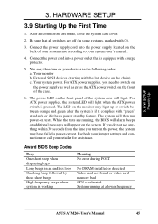
... where system activity will turn off . This is a preferred method of rebooting to prolong the life of certain components when the system is in use. ASUS A7M266 User's Manual 43 The LED will switch the system between ON and SLEEP or ON and SOFT OFF, depending on and blinks when it is... not in sleep or soft-off mode. 23) System Warning Speaker Connector (4-pin SPEAKER) This 4-pin connector connects to turn the system off your BIOS or OS setting. Pushing the button once will remain lit when there is no signal and blink when there is powered on your power switch...
... where system activity will turn off . This is a preferred method of rebooting to prolong the life of certain components when the system is in use. ASUS A7M266 User's Manual 43 The LED will switch the system between ON and SLEEP or ON and SOFT OFF, depending on and blinks when it is... not in sleep or soft-off mode. 23) System Warning Speaker Connector (4-pin SPEAKER) This 4-pin connector connects to turn the system off your BIOS or OS setting. Pushing the button once will remain lit when there is no signal and blink when there is powered on your power switch...
Motherboard DIY Troubleshooting Guide
Page 45
...No error during POST No DRAM installed or detected Video card not found or video card memory bad CPU overheated System running , the BIOS will alarm beeps or additional messages will light when the ATX power switch is pressed. The system will light. Your system power. ... Award BIOS Beep Codes Beep One short beep when displaying logo Long beeps in some systems, marked with a surge protector. 5. While the tests are made, close the system case cover. 2. Connect the power supply cord into a power outlet that all connections are running at a lower frequency ASUS A7M266 User...
...No error during POST No DRAM installed or detected Video card not found or video card memory bad CPU overheated System running , the BIOS will alarm beeps or additional messages will light when the ATX power switch is pressed. The system will light. Your system power. ... Award BIOS Beep Codes Beep One short beep when displaying logo Long beeps in some systems, marked with a surge protector. 5. While the tests are made, close the system case cover. 2. Connect the power supply cord into a power outlet that all connections are running at a lower frequency ASUS A7M266 User...

Motherboard DIY Troubleshooting Guide
Page 46
... down your operating system before switching off your computer" will not appear when shutting down to enter BIOS setup. During power-on, hold down with ATX power supplies. 3. H/W SETUP Powering Up 46 ASUS A7M266 User's Manual BIOS SETUP. * Powering Off your operating system. The power supply should turn off the power switch. HARDWARE SETUP...
... down your operating system before switching off your computer" will not appear when shutting down to enter BIOS setup. During power-on, hold down with ATX power supplies. 3. H/W SETUP Powering Up 46 ASUS A7M266 User's Manual BIOS SETUP. * Powering Off your operating system. The power supply should turn off the power switch. HARDWARE SETUP...

Motherboard DIY Troubleshooting Guide
Page 47
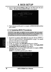
...utility that may be programmed by uploading a new BIOS file to reinstall the BIOS later. To determine the BIOS version of your hard drive. Larger numbers represent a newer BIOS file. 1. BIOS SETUP 4.1 Managing and Updating Your BIOS 4.1.1 Upon First Use of your CDROM drive) to... copy AFLASH.EXE to run AFLASH. 4. Type COPY D:\AFLASH\AFLASH.EXE A:\ (assuming D is your screen during bootup. In DOS mode, type A:\AFLASH to the just created boot disk. ASUS A7M266...
...utility that may be programmed by uploading a new BIOS file to reinstall the BIOS later. To determine the BIOS version of your hard drive. Larger numbers represent a newer BIOS file. 1. BIOS SETUP 4.1 Managing and Updating Your BIOS 4.1.1 Upon First Use of your CDROM drive) to... copy AFLASH.EXE to run AFLASH. 4. Type COPY D:\AFLASH\AFLASH.EXE A:\ (assuming D is your screen during bootup. In DOS mode, type A:\AFLASH to the just created boot disk. ASUS A7M266...
Motherboard DIY Troubleshooting Guide
Page 48
...Main menu and press . Download an updated ASUS BIOS file from the disk you created earlier. 3. The Save Current BIOS To File screen appears. 6. The Update BIOS Including Boot Block and ESCD screen appears. 5. Select 1. Only update your BIOS if you have problems with your motherboard and ...and then press . 4. Save Current BIOS to the disk you know that the new BIOS revision will solve your problems. Careless updating can result in your new BIOS and the path, for example, A:\XXXXX.XXX, and then press . BIOS SETUP Updating BIOS 48 ASUS A7M266 User's Manual 4. Type the filename...
...Main menu and press . Download an updated ASUS BIOS file from the disk you created earlier. 3. The Save Current BIOS To File screen appears. 6. The Update BIOS Including Boot Block and ESCD screen appears. 5. Select 1. Only update your BIOS if you have problems with your motherboard and ...and then press . 4. Save Current BIOS to the disk you know that the new BIOS revision will solve your problems. Careless updating can result in your new BIOS and the path, for example, A:\XXXXX.XXX, and then press . BIOS SETUP Updating BIOS 48 ASUS A7M266 User's Manual 4. Type the filename...

Motherboard DIY Troubleshooting Guide
Page 49
... will need servicing. If you saved to continue. WARNING! If the Flash Memory Writer utility was not able to successfully update a complete BIOS file, your system will prevent your system from booting up . If this might prevent your system from booting up . The boot block ... still persists, update the original BIOS file you encounter problems while updating the new BIOS, DO NOT turn off your system since this happens, your system may not be able to program the new BIOS information into the flash ROM. BIOS SETUP 6. ASUS A7M266 User's Manual 49 When prompted to...
... will need servicing. If you saved to continue. WARNING! If the Flash Memory Writer utility was not able to successfully update a complete BIOS file, your system will prevent your system from booting up . If this might prevent your system from booting up . The boot block ... still persists, update the original BIOS file you encounter problems while updating the new BIOS, DO NOT turn off your system since this happens, your system may not be able to program the new BIOS information into the flash ROM. BIOS SETUP 6. ASUS A7M266 User's Manual 49 When prompted to...


