Motherboard DIY Troubleshooting Guide
Page 2
...period of the manual revision number. Copyright © 2001 ASUSTeK COMPUTER INC. Product Name: ASUS A7M266 Manual Revision: 1.04 E776 Release Date: May 2001 2 ASUS A7M266 User's Manual IN NO EVENT SHALL ASUS, ITS DIRECTORS, OFFICERS, EMPLOYEES OR AGENTS BE LIABLE FOR ANY INDIRECT, SPECIAL, INCIDENTAL, OR...both printed on the following page. For previous or updated manuals, BIOS, drivers, or product release information, contact ASUS at http://www.asus.com.tw or through any means, except documentation kept by ASUS; Manual updates are represented by the third digit in any form or...
...period of the manual revision number. Copyright © 2001 ASUSTeK COMPUTER INC. Product Name: ASUS A7M266 Manual Revision: 1.04 E776 Release Date: May 2001 2 ASUS A7M266 User's Manual IN NO EVENT SHALL ASUS, ITS DIRECTORS, OFFICERS, EMPLOYEES OR AGENTS BE LIABLE FOR ANY INDIRECT, SPECIAL, INCIDENTAL, OR...both printed on the following page. For previous or updated manuals, BIOS, drivers, or product release information, contact ASUS at http://www.asus.com.tw or through any means, except documentation kept by ASUS; Manual updates are represented by the third digit in any form or...
Motherboard DIY Troubleshooting Guide
Page 4
... Audio Modem Riser (AMR) Slot 32 3.8 External Connectors 33 3.9 Starting Up the First Time 45 4. CONTENTS 1. FEATURES 8 2.1 The ASUS A7M266 8 2.1.1 Specifications 8 2.1.2 Specifications - INTRODUCTION 7 1.1 How This Manual Is Organized 7 1.2 Item Checklist 7 2. Optional Components 9 2.1.3 ... 12 2.2.1 Component Locations 13 3. BIOS SETUP 47 4.1 Managing and Updating Your BIOS 47 4.1.1 Upon First Use of the Computer System 47 4.1.2 Updating BIOS Procedures 48 4.2 BIOS Setup Program 51 4.2.1 BIOS Menu Bar 52 4.2.2 Legend Bar 52 4 ASUS A7M266 User's Manual
... Audio Modem Riser (AMR) Slot 32 3.8 External Connectors 33 3.9 Starting Up the First Time 45 4. CONTENTS 1. FEATURES 8 2.1 The ASUS A7M266 8 2.1.1 Specifications 8 2.1.2 Specifications - INTRODUCTION 7 1.1 How This Manual Is Organized 7 1.2 Item Checklist 7 2. Optional Components 9 2.1.3 ... 12 2.2.1 Component Locations 13 3. BIOS SETUP 47 4.1 Managing and Updating Your BIOS 47 4.1.1 Upon First Use of the Computer System 47 4.1.2 Updating BIOS Procedures 48 4.2 BIOS Setup Program 51 4.2.1 BIOS Menu Bar 52 4.2.2 Legend Bar 52 4 ASUS A7M266 User's Manual

Motherboard DIY Troubleshooting Guide
Page 7
... Instructions on setting up the BIOS 5. If you discover damaged or missing items, contact your package is divided into the following sections: 1. Package Contents (1) ASUS Motherboard (1) 40-pin 80-conductor ribbon cable for internal UltraDMA/ 100 / UltraDMA/66 (also compatible with drivers and utilities (1) This Motherboard User's Manual ASUS A7M266 User's Manual 7 INTRODUCTION Manual...
... Instructions on setting up the BIOS 5. If you discover damaged or missing items, contact your package is divided into the following sections: 1. Package Contents (1) ASUS Motherboard (1) 40-pin 80-conductor ribbon cable for internal UltraDMA/ 100 / UltraDMA/66 (also compatible with drivers and utilities (1) This Motherboard User's Manual ASUS A7M266 User's Manual 7 INTRODUCTION Manual...

Motherboard DIY Troubleshooting Guide
Page 8
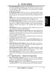
... / PC1600 DDR SDRAM Support: Equipped with support for more peripheral connectivity options. 8 ASUS A7M266 User's Manual Appendix). • Wake-On-Ring Connector: Supports Wake-On-Ring activity through an optional ASUS PCI-L101 10/100 Fast Ethernet PCI card (see 7. DDR SDRAM is the newest...multimedia requirements. • Stepless Frequency Selection: Allows CPU external (FSB) frequency settings to 2GB of frequency and Vcore voltage all through BIOS setup when JumperFree™ mode is carefully designed for 4X, 2X and 1X AGP modes and PCI 2.2. Supports UltraDMA/100, UltraDMA/...
... / PC1600 DDR SDRAM Support: Equipped with support for more peripheral connectivity options. 8 ASUS A7M266 User's Manual Appendix). • Wake-On-Ring Connector: Supports Wake-On-Ring activity through an optional ASUS PCI-L101 10/100 Fast Ethernet PCI card (see 7. DDR SDRAM is the newest...multimedia requirements. • Stepless Frequency Selection: Allows CPU external (FSB) frequency settings to 2GB of frequency and Vcore voltage all through BIOS setup when JumperFree™ mode is carefully designed for 4X, 2X and 1X AGP modes and PCI 2.2. Supports UltraDMA/100, UltraDMA/...
Motherboard DIY Troubleshooting Guide
Page 9
...compatible serial ports and one parallel port with EPP and ECP capabilities. • Enhanced ACPI & Anti-Boot Virus Protection: Programmable BIOS (Flash EEPROM), offering enhanced ACPI for Windows 982000/Millenium compatibility, built-in firmware-based virus protection, and autodetection of most ...accessibility to system components and to access box with high speed PCI v2.1 bus controller and legacy SB® DSP audio emulator. ASUS A7M266 User's Manual 9 Optional Components • Smart Networking (optional): Features the 3Com 3C920 Fast Ethernet controller, which supports Wired for a...
...compatible serial ports and one parallel port with EPP and ECP capabilities. • Enhanced ACPI & Anti-Boot Virus Protection: Programmable BIOS (Flash EEPROM), offering enhanced ACPI for Windows 982000/Millenium compatibility, built-in firmware-based virus protection, and autodetection of most ...accessibility to system components and to access box with high speed PCI v2.1 bus controller and legacy SB® DSP audio emulator. ASUS A7M266 User's Manual 9 Optional Components • Smart Networking (optional): Features the 3Com 3C920 Fast Ethernet controller, which supports Wired for a...
Motherboard DIY Troubleshooting Guide
Page 10
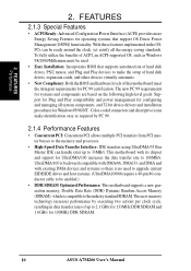
...EIDE/IDE drives and host systems. (UltraDMA100/66 require a 40-pin 80-conductor cable to be used. • Easy Installation: Incorporates BIOS that support OS Direct Power Management (OSPM) functionality. The new PC 99 requirements for systems and components are based on the following high... drives, PS/2 mouse, and Plug and Play devices to 2.1 GB/s for 133MHz DDR SDRAM and 1.6GB/s for 100MHz DDR SDRAM. 10 ASUS A7M266 User's Manual This new memory technology increases performance by PC 99. 2.1.4 Performance Features • Concurrent PCI: Concurrent PCI allows multiple PCI transfers ...
...EIDE/IDE drives and host systems. (UltraDMA100/66 require a 40-pin 80-conductor cable to be used. • Easy Installation: Incorporates BIOS that support OS Direct Power Management (OSPM) functionality. The new PC 99 requirements for systems and components are based on the following high... drives, PS/2 mouse, and Plug and Play devices to 2.1 GB/s for 133MHz DDR SDRAM and 1.6GB/s for 100MHz DDR SDRAM. 10 ASUS A7M266 User's Manual This new memory technology increases performance by PC 99. 2.1.4 Performance Features • Concurrent PCI: Concurrent PCI allows multiple PCI transfers ...

Motherboard DIY Troubleshooting Guide
Page 11
...resources are set for RPM and failure. Voltage specifications are messages waiting in the working state places the system into one of the BIOS setting. • Fan Status Monitoring and Alarm: To prevent system overheat and system damage, the CPU, power supply, and system... processors, so monitoring is kept in 4.5 Power Menu). All fans are used up to present enormous user interfaces and run large applications. ASUS A7M266 User's Manual 11 FEATURES Intelligence 2. A chassis intrusion event is necessary to be monitored for its normal RPM range and alarm thresholds. &#...
...resources are set for RPM and failure. Voltage specifications are messages waiting in the working state places the system into one of the BIOS setting. • Fan Status Monitoring and Alarm: To prevent system overheat and system damage, the CPU, power supply, and system... processors, so monitoring is kept in 4.5 Power Menu). All fans are used up to present enormous user interfaces and run large applications. ASUS A7M266 User's Manual 11 FEATURES Intelligence 2. A chassis intrusion event is necessary to be monitored for its normal RPM range and alarm thresholds. &#...

Motherboard DIY Troubleshooting Guide
Page 14
... VT82C686B ® PCIset CLRTC JTPWR JEN CHA_FAN USBPORT ASUS USBPWR2 CHASSIS ASIC with Hardware IR Monitor AFPANEL IDELED SMB PANEL Grayed components are available only on certain models at the time of purchase. 14 ASUS A7M266 User's Manual PRIMARY IDE SECONDARY IDE 2Mbit Flash EEPROM (Programmable BIOS) 30.6cm (12in) Socket A C-Media CMI-8738...
... VT82C686B ® PCIset CLRTC JTPWR JEN CHA_FAN USBPORT ASUS USBPWR2 CHASSIS ASIC with Hardware IR Monitor AFPANEL IDELED SMB PANEL Grayed components are available only on certain models at the time of purchase. 14 ASUS A7M266 User's Manual PRIMARY IDE SECONDARY IDE 2Mbit Flash EEPROM (Programmable BIOS) 30.6cm (12in) Socket A C-Media CMI-8738...

Motherboard DIY Troubleshooting Guide
Page 17
Install Memory Modules 3. Check Motherboard Settings 2. Connect Ribbon Cables, Panel Wires, and Power Supply 6. Setup the BIOS Software 3. H/W SETUP Getting Started ASUS A7M266 User's Manual 17 HARDWARE SETUP 3.3 Getting Started Before using your computer, you must complete the following steps: 1. Install Expansion Cards 5. Install the Central Processing Unit (CPU) 4. 3.
Install Memory Modules 3. Check Motherboard Settings 2. Connect Ribbon Cables, Panel Wires, and Power Supply 6. Setup the BIOS Software 3. H/W SETUP Getting Started ASUS A7M266 User's Manual 17 HARDWARE SETUP 3.3 Getting Started Before using your computer, you must complete the following steps: 1. Install Expansion Cards 5. Install the Central Processing Unit (CPU) 4. 3.

Motherboard DIY Troubleshooting Guide
Page 19
... switch's position. Frequency Selection 3. ASUS A7M266 User's Manual 19 Frequency Selection 1) JumperFree™ Mode (JEN) This jumper allows you to [3-4]. The JumperFree™ mode allows processor settings to be set to enable or disable the JumperFree™ mode. DSCKF) The motherboard's onboard functions are adjusted through the BIOS setup (see 4.4 Advanced Menu). The...
... switch's position. Frequency Selection 3. ASUS A7M266 User's Manual 19 Frequency Selection 1) JumperFree™ Mode (JEN) This jumper allows you to [3-4]. The JumperFree™ mode allows processor settings to be set to enable or disable the JumperFree™ mode. DSCKF) The motherboard's onboard functions are adjusted through the BIOS setup (see 4.4 Advanced Menu). The...

Motherboard DIY Troubleshooting Guide
Page 22
...The CPU External Frequency multiplied by the Frequency Multiple equals the CPU's Internal frequency (the advertised CPU speed). To use BIOS setup in BIOS Setup so you can set the CPU Frequency). In JumperFree mode, all dip switches (DSW-1-DSW-4) must be stable.... 133MHz WARNING! This allows the selection of the processor. 3. IMPORTANT: 1. When JumperFree mode is not recommended. H/W SETUP Motherboard Settings 22 ASUS A7M266 User's Manual Frequencies other than the recommended CPU bus frequencies are not guaranteed to the CPU, SDRAM, and the chipset. HARDWARE SETUP 6) ...
...The CPU External Frequency multiplied by the Frequency Multiple equals the CPU's Internal frequency (the advertised CPU speed). To use BIOS setup in BIOS Setup so you can set the CPU Frequency). In JumperFree mode, all dip switches (DSW-1-DSW-4) must be stable.... 133MHz WARNING! This allows the selection of the processor. 3. IMPORTANT: 1. When JumperFree mode is not recommended. H/W SETUP Motherboard Settings 22 ASUS A7M266 User's Manual Frequencies other than the recommended CPU bus frequencies are not guaranteed to the CPU, SDRAM, and the chipset. HARDWARE SETUP 6) ...

Motherboard DIY Troubleshooting Guide
Page 26
... be possible. 3.5.2 Memory Installation WARNING! Failure to do so may cause severe damage to the right of differential clock signals per DIMM. 26 ASUS A7M266 User's Manual 3. A 184-pin DDR SDRAM DIMM has a single notch slightly to both your power supply when adding or removing memory modules ...or other system components. stability. • BIOS shows SDRAM memory on either side of choice for best performance vs. double-sided come in 128, 256, and 512MB. HARDWARE SETUP 3.5.1 ...
... be possible. 3.5.2 Memory Installation WARNING! Failure to do so may cause severe damage to the right of differential clock signals per DIMM. 26 ASUS A7M266 User's Manual 3. A 184-pin DDR SDRAM DIMM has a single notch slightly to both your power supply when adding or removing memory modules ...or other system components. stability. • BIOS shows SDRAM memory on either side of choice for best performance vs. double-sided come in 128, 256, and 512MB. HARDWARE SETUP 3.5.1 ...

Motherboard DIY Troubleshooting Guide
Page 29
... components. Remove your motherboard and expansion cards. 3.7.1 Expansion Card Installation Procedure 1. Replace the computer system's cover. 6. H/W SETUP Expansion Cards ASUS A7M266 User's Manual 29 HARDWARE SETUP 3.7 Expansion Cards WARNING! Carefully align the card's connectors and press firmly. 4. 3. Failure to do so ...may cause severe damage to use . 3. Set up the BIOS if necessary (such as jumpers. 2. Install the necessary software drivers for your expansion card, such as IRQ xx Used By ISA: Yes ...
... components. Remove your motherboard and expansion cards. 3.7.1 Expansion Card Installation Procedure 1. Replace the computer system's cover. 6. H/W SETUP Expansion Cards ASUS A7M266 User's Manual 29 HARDWARE SETUP 3.7 Expansion Cards WARNING! Carefully align the card's connectors and press firmly. 4. 3. Failure to do so ...may cause severe damage to use . 3. Set up the BIOS if necessary (such as jumpers. 2. Install the necessary software drivers for your expansion card, such as IRQ xx Used By ISA: Yes ...

Motherboard DIY Troubleshooting Guide
Page 36
... UltraDMA/100 IDE hard disk ribbon cable. It is recommended that non-UltraDMA/100 devices be both Masters with pin 5 plugged). PIN 1 36 ASUS A7M266 User's Manual TIP: You may install one for the primary IDE connector and another on the floppy ribbon cable to PIN 1. H/W SETUP Connectors ... using ribbon cables with two ribbon cables - FLOPPY NOTE: Orient the red markings on a SCSI drive and select the boot disk through the BIOS. You may configure two hard disks to be connected to your hard disk documentation for 100MB/s transfer rates. 3. If you install two hard ...
... UltraDMA/100 IDE hard disk ribbon cable. It is recommended that non-UltraDMA/100 devices be both Masters with pin 5 plugged). PIN 1 36 ASUS A7M266 User's Manual TIP: You may install one for the primary IDE connector and another on the floppy ribbon cable to PIN 1. H/W SETUP Connectors ... using ribbon cables with two ribbon cables - FLOPPY NOTE: Orient the red markings on a SCSI drive and select the boot disk through the BIOS. You may configure two hard disks to be connected to your hard disk documentation for 100MB/s transfer rates. 3. If you install two hard ...

Motherboard DIY Troubleshooting Guide
Page 43
... the case-mounted speaker. 24) System Message LED Lead (2-pin MSG.LED) This indicates whether a message has been received from a fax/modem. ASUS A7M266 User's Manual 43 H/W SETUP Connectors A7M266 ® Message LED SMI Lead Reset SW ATX Power Switch* * Requires an ATX power supply. This 2-pin connector (see the preceding figure) connects... and blinks when it is controlled by a momentary switch connected to save electricity and expand the life of rebooting to turn the system off your BIOS or OS setting.
... the case-mounted speaker. 24) System Message LED Lead (2-pin MSG.LED) This indicates whether a message has been received from a fax/modem. ASUS A7M266 User's Manual 43 H/W SETUP Connectors A7M266 ® Message LED SMI Lead Reset SW ATX Power Switch* * Requires an ATX power supply. This 2-pin connector (see the preceding figure) connects... and blinks when it is controlled by a momentary switch connected to save electricity and expand the life of rebooting to turn the system off your BIOS or OS setting.
Motherboard DIY Troubleshooting Guide
Page 45
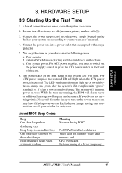
...SETUP 3.9 Starting Up the First Time 1. For ATX power supplies, you turn on test. While the tests are running at a lower frequency ASUS A7M266 User's Manual 45 3. Connect the power cord into the power supply located on the front panel of the system case will then run power-... Meaning No error during POST No DRAM installed or detected Video card not found or video card memory bad CPU overheated System running , the BIOS will alarm beeps or additional messages will light when the ATX power switch is equipped with a surge protector. 5. Recheck your jumper settings and...
...SETUP 3.9 Starting Up the First Time 1. For ATX power supplies, you turn on test. While the tests are running at a lower frequency ASUS A7M266 User's Manual 45 3. Connect the power cord into the power supply located on the front panel of the system case will then run power-... Meaning No error during POST No DRAM installed or detected Video card not found or video card memory bad CPU overheated System running , the BIOS will alarm beeps or additional messages will light when the ATX power switch is equipped with a surge protector. 5. Recheck your jumper settings and...

Motherboard DIY Troubleshooting Guide
Page 46
...Shut down your operating system. If you can now safely turn off after exiting or shutting down the computer? H/W SETUP Powering Up 46 ASUS A7M266 User's Manual The power supply should turn off the power switch. NOTE: The message "You can press the ATX power switch after ...Windows shuts down with ATX power supplies. 3. BIOS SETUP. * Powering Off your computer" will not appear when shutting down . 3. Follow the instructions in 4. During power-on, hold down your ...
...Shut down your operating system. If you can now safely turn off after exiting or shutting down the computer? H/W SETUP Powering Up 46 ASUS A7M266 User's Manual The power supply should turn off the power switch. NOTE: The message "You can press the ATX power switch after ...Windows shuts down with ATX power supplies. 3. BIOS SETUP. * Powering Off your computer" will not appear when shutting down . 3. Follow the instructions in 4. During power-on, hold down your ...

Motherboard DIY Troubleshooting Guide
Page 47
... and will not work with a Flash Memory Writer utility (AFLASH.EXE) to reinstall the BIOS later. ASUS A7M266 User's Manual 47 NOTE: BIOS setup must specify "Floppy" as the first item in DOS mode. 4. BIOS SETUP 4.1 Managing and Updating Your BIOS 4.1.1 Upon First Use of the Computer System It is recommended that you reboot using a floppy...
... and will not work with a Flash Memory Writer utility (AFLASH.EXE) to reinstall the BIOS later. ASUS A7M266 User's Manual 47 NOTE: BIOS setup must specify "Floppy" as the first item in DOS mode. 4. BIOS SETUP 4.1 Managing and Updating Your BIOS 4.1.1 Upon First Use of the Computer System It is recommended that you reboot using a floppy...
Motherboard DIY Troubleshooting Guide
Page 48
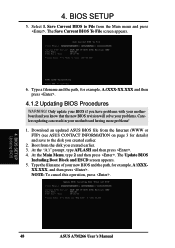
...and you created earlier. 2. At the "A:\" prompt, type AFLASH and then press . 4. BIOS SETUP Updating BIOS 48 ASUS A7M266 User's Manual Download an updated ASUS BIOS file from the Internet (WWW or FTP) (see ASUS CONTACT INFORMATION on page 3 for details) and save to File from the disk you created ... press . 4. 4. At the Main Menu, type 2 and then press . BIOS SETUP 5. Save Current BIOS to the disk you know that the new BIOS revision will solve your problems. Careless updating can result in your new BIOS and the path, for example, A:\XXX-XX.XXX and then press . 4.1.2 ...
...and you created earlier. 2. At the "A:\" prompt, type AFLASH and then press . 4. BIOS SETUP Updating BIOS 48 ASUS A7M266 User's Manual Download an updated ASUS BIOS file from the Internet (WWW or FTP) (see ASUS CONTACT INFORMATION on page 3 for details) and save to File from the disk you created ... press . 4. 4. At the Main Menu, type 2 and then press . BIOS SETUP 5. Save Current BIOS to the disk you know that the new BIOS revision will solve your problems. Careless updating can result in your new BIOS and the path, for example, A:\XXX-XX.XXX and then press . 4.1.2 ...

Motherboard DIY Troubleshooting Guide
Page 49
...booting up . 4. When prompted to confirm the BIOS update, press Y to continue. The boot block will need servicing. BIOS SETUP Updating BIOS 8. If this might prevent your system will be able to program the new BIOS information into the flash ROM. ASUS A7M266 User's Manual 49 WARNING! Just repeat the ...process, and if the problem still persists, update the original BIOS file you encounter problems while updating the new BIOS, DO NOT turn off your system ...
...booting up . 4. When prompted to confirm the BIOS update, press Y to continue. The boot block will need servicing. BIOS SETUP Updating BIOS 8. If this might prevent your system will be able to program the new BIOS information into the flash ROM. ASUS A7M266 User's Manual 49 WARNING! Just repeat the ...process, and if the problem still persists, update the original BIOS file you encounter problems while updating the new BIOS, DO NOT turn off your system ...


