Motherboard DIY Troubleshooting Guide
Page 4
... Computer System 47 4.1.2 Updating BIOS Procedures 48 4.2 BIOS Setup Program 51 4.2.1 BIOS Menu Bar 52 4.2.2 Legend Bar 52 4 ASUS A7M266 User's Manual INTRODUCTION 7 1.1 How This Manual Is Organized 7 1.2 Item Checklist 7 2. HARDWARE SETUP 14 3.1 Motherboard Layout 14... 3.2 Layout Contents 15 3.3 Getting Started 17 3.4 Motherboard Settings 18 3.5 System Memory (DDR DIMM 25 3.5.1 General DIMM Notes 26 3.5.2 Memory Installation 26 3.6 Central Processing Unit (CPU 27 3.7 Expansion Cards 28 3.7.1 Expansion Card Installation Procedure 28...
... Computer System 47 4.1.2 Updating BIOS Procedures 48 4.2 BIOS Setup Program 51 4.2.1 BIOS Menu Bar 52 4.2.2 Legend Bar 52 4 ASUS A7M266 User's Manual INTRODUCTION 7 1.1 How This Manual Is Organized 7 1.2 Item Checklist 7 2. HARDWARE SETUP 14 3.1 Motherboard Layout 14... 3.2 Layout Contents 15 3.3 Getting Started 17 3.4 Motherboard Settings 18 3.5 System Memory (DDR DIMM 25 3.5.1 General DIMM Notes 26 3.5.2 Memory Installation 26 3.6 Central Processing Unit (CPU 27 3.7 Expansion Cards 28 3.7.1 Expansion Card Installation Procedure 28...

Motherboard DIY Troubleshooting Guide
Page 8
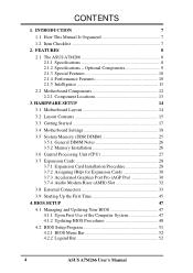
... Supports Socket A-based AMD Athlon™/Duron™ processors. • North Bridge System Chipset: AMD-761™ chipset with AGP/PCI/Memory controller supports a 266MHz Front Side Bus (FSB), supports DDR SDRAM DIMM, complies with AGP 2.0 specifications for UltraDMA/100, which allows burst.... • USB: Supports up to allow manual adjustment of jumpers are included to 4 USB ports, two on two channels. FEATURES 2.1 The ASUS A7M266 The ASUS A7M266 motherboard is enabled. Supports UltraDMA/100, UltraDMA/66, UltraDMA/33, PIO Modes 3 & 4 and Bus Master IDE DMA Mode 2, and Enhanced ...
... Supports Socket A-based AMD Athlon™/Duron™ processors. • North Bridge System Chipset: AMD-761™ chipset with AGP/PCI/Memory controller supports a 266MHz Front Side Bus (FSB), supports DDR SDRAM DIMM, complies with AGP 2.0 specifications for UltraDMA/100, which allows burst.... • USB: Supports up to allow manual adjustment of jumpers are included to 4 USB ports, two on two channels. FEATURES 2.1 The ASUS A7M266 The ASUS A7M266 motherboard is enabled. Supports UltraDMA/100, UltraDMA/66, UltraDMA/33, PIO Modes 3 & 4 and Bus Master IDE DMA Mode 2, and Enhanced ...
Motherboard DIY Troubleshooting Guide
Page 9
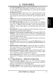
...• Enhanced ACPI & Anti-Boot Virus Protection: Programmable BIOS (Flash EEPROM), offering enhanced ACPI for a hard disk drive. ASUS A7M266 User's Manual 9 With an ASUS iPanel, you can monitor your computer system's vital components. • PC Health Monitoring: Provides an easy way to examine and ... most devices for virtually automatic setup. • Concurrent PCI: Concurrent PCI allows multiple PCI transfers from PCI master busses to the memory and processor. • Smart BIOS: 2Mb firmware provides Vcore and CPU/SDRAM frequency adjustments, boot block write protection, and HD...
...• Enhanced ACPI & Anti-Boot Virus Protection: Programmable BIOS (Flash EEPROM), offering enhanced ACPI for a hard disk drive. ASUS A7M266 User's Manual 9 With an ASUS iPanel, you can monitor your computer system's vital components. • PC Health Monitoring: Provides an easy way to examine and ... most devices for virtually automatic setup. • Concurrent PCI: Concurrent PCI allows multiple PCI transfers from PCI master busses to the memory and processor. • Smart BIOS: 2Mb firmware provides Vcore and CPU/SDRAM frequency adjustments, boot block write protection, and HD...
Motherboard DIY Troubleshooting Guide
Page 10
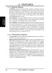
... must be used. • Easy Installation: Incorporates BIOS that support OS Direct Power Management (OSPM) functionality. This new memory technology increases performance by PC 99. 2.1.4 Performance Features • Concurrent PCI: Concurrent PCI allows multiple PCI transfers from PCI master busses... are based on the following high-level goals: Support for Plug and Play compatibility and power management for 100MHz DDR SDRAM. 10 ASUS A7M266 User's Manual FEATURES 2.1.3 Special Features • ACPI Ready: Advanced Configuration Power Interface (ACPI) provides more Energy Saving Features for ...
... must be used. • Easy Installation: Incorporates BIOS that support OS Direct Power Management (OSPM) functionality. This new memory technology increases performance by PC 99. 2.1.4 Performance Features • Concurrent PCI: Concurrent PCI allows multiple PCI transfers from PCI master busses... are based on the following high-level goals: Support for Plug and Play compatibility and power management for 100MHz DDR SDRAM. 10 ASUS A7M266 User's Manual FEATURES 2.1.3 Special Features • ACPI Ready: Advanced Configuration Power Interface (ACPI) provides more Energy Saving Features for ...

Motherboard DIY Troubleshooting Guide
Page 11
... Power Button: Pushing the power button for less than 4 seconds, the system enters the soft-off mode, depending on remotely through the ASUS ASIC. All fans are used up to critical motherboard components. A simple glimpse provides useful information to the user. • Remote Ring...System voltage levels are monitored to ensure stable voltage to prevent possible application crashes. ASUS A7M266 User's Manual 11 Suggestions will warn the user before the system resources are set for more memory and hard drive space to ensure proper system configuration and management. • ...
... Power Button: Pushing the power button for less than 4 seconds, the system enters the soft-off mode, depending on remotely through the ASUS ASIC. All fans are used up to critical motherboard components. A simple glimpse provides useful information to the user. • Remote Ring...System voltage levels are monitored to ensure stable voltage to prevent possible application crashes. ASUS A7M266 User's Manual 11 Suggestions will warn the user before the system resources are set for more memory and hard drive space to ensure proper system configuration and management. • ...

Motherboard DIY Troubleshooting Guide
Page 12
...the CPU socket) Chipsets AMD 761 system controller 1 VIA VT82C686B PCIset 8 2Mbit Programmable Flash EEPROM 6 Main Memory Maximum 2GB support 2 DIMM Sockets 3 PC2100 / PC1600 DDR memory support Expansion Slots 5 PCI Slots 16 1 Accelerated Graphics Port (AGP) Pro Slot 17 1 Audio Modem Riser...-LAN Connector 12 Wake-On-Ring Connector 10 Hardware Monitoring ASUS ASIC 9 3 Fan Power and Speed Monitoring Connectors Power ATX Power Supply Connector 18 Special Feature Onboard LED 11 Form Factor ATX 12 ASUS A7M266 User's Manual Location Processor Support Socket 462 for locations....
...the CPU socket) Chipsets AMD 761 system controller 1 VIA VT82C686B PCIset 8 2Mbit Programmable Flash EEPROM 6 Main Memory Maximum 2GB support 2 DIMM Sockets 3 PC2100 / PC1600 DDR memory support Expansion Slots 5 PCI Slots 16 1 Accelerated Graphics Port (AGP) Pro Slot 17 1 Audio Modem Riser...-LAN Connector 12 Wake-On-Ring Connector 10 Hardware Monitoring ASUS ASIC 9 3 Fan Power and Speed Monitoring Connectors Power ATX Power Supply Connector 18 Special Feature Onboard LED 11 Form Factor ATX 12 ASUS A7M266 User's Manual Location Processor Support Socket 462 for locations....

Motherboard DIY Troubleshooting Guide
Page 15
ASUS A7M266 User's Manual 15 3. HARDWARE SETUP 3.2 Layout Contents 3. H/W SETUP Layout Contents Motherboard Settings 1) JEN p. 19 JumperFree Mode (JumperFree / Jumper Mode) 2) VIO VIO1 p. 20 Clock .../ Enable) 6) DSCKF 1-4 p. 22 CPU External Frequency Setting 7) VID1/VID2/VID3/VID4 p. 24 Voltage Regulator Output Setting Expansion Slots/Sockets 1) DDR System Memory p. 25 System Memory Support 2) DIMM1/2 p. 26 DDR DIMM Memory Module Support 3) Socket 462 (Socket A) p. 27 CPU Support 4) PCI1/2/3/4/5 p. 29 32-bit PCI Bus Expansion Slots 5) AGP PRO p. 31 Accelerated Graphics...
ASUS A7M266 User's Manual 15 3. HARDWARE SETUP 3.2 Layout Contents 3. H/W SETUP Layout Contents Motherboard Settings 1) JEN p. 19 JumperFree Mode (JumperFree / Jumper Mode) 2) VIO VIO1 p. 20 Clock .../ Enable) 6) DSCKF 1-4 p. 22 CPU External Frequency Setting 7) VID1/VID2/VID3/VID4 p. 24 Voltage Regulator Output Setting Expansion Slots/Sockets 1) DDR System Memory p. 25 System Memory Support 2) DIMM1/2 p. 26 DDR DIMM Memory Module Support 3) Socket 462 (Socket A) p. 27 CPU Support 4) PCI1/2/3/4/5 p. 29 32-bit PCI Bus Expansion Slots 5) AGP PRO p. 31 Accelerated Graphics...

Motherboard DIY Troubleshooting Guide
Page 17
Setup the BIOS Software 3. Install Memory Modules 3. Install Expansion Cards 5. HARDWARE SETUP 3.3 Getting Started Before using your computer, you must complete the following steps: 1. Install the Central Processing Unit (CPU) 4. H/W SETUP Getting Started ASUS A7M266 User's Manual 17 Connect Ribbon Cables, Panel Wires, and Power Supply 6. Check Motherboard Settings 2. 3.
Setup the BIOS Software 3. Install Memory Modules 3. Install Expansion Cards 5. HARDWARE SETUP 3.3 Getting Started Before using your computer, you must complete the following steps: 1. Install the Central Processing Unit (CPU) 4. H/W SETUP Getting Started ASUS A7M266 User's Manual 17 Connect Ribbon Cables, Panel Wires, and Power Supply 6. Check Motherboard Settings 2. 3.

Motherboard DIY Troubleshooting Guide
Page 25
... as follows: DIMM Location Socket 1 (Rows 0&1) Socket 2 (Rows 2&3) 184-pin DIMM Total Memory 64MB, 128MB, 256MB, 512MB, 1GB x1 64MB, 128MB, 256MB, 512MB, 1GB x1 Total System Memory (Max 2GB) = ASUS A7M266 Qualified DDR DIMM Vendor List The following lists the memory modules that have been tested and qualified for 2.5Volt (power level) unbuffered/registered...
... as follows: DIMM Location Socket 1 (Rows 0&1) Socket 2 (Rows 2&3) 184-pin DIMM Total Memory 64MB, 128MB, 256MB, 512MB, 1GB x1 64MB, 128MB, 256MB, 512MB, 1GB x1 Total System Memory (Max 2GB) = ASUS A7M266 Qualified DDR DIMM Vendor List The following lists the memory modules that have been tested and qualified for 2.5Volt (power level) unbuffered/registered...

Motherboard DIY Troubleshooting Guide
Page 26
...SETUP System Memory 01 01 A7M266 ® A7M266 184-Pin DDR DIMM Sockets This motherboard supports three pairs of center. 3. double-sided come in the orientation shown. WARNING! 3. Failure to do so may cause severe damage to the right of differential clock signals per DIMM. 26 ASUS A7M266 User's... Manual A 184-pin DDR SDRAM DIMM has a single notch slightly to both your power supply when adding or removing memory modules or other system components.
...SETUP System Memory 01 01 A7M266 ® A7M266 184-Pin DDR DIMM Sockets This motherboard supports three pairs of center. 3. double-sided come in the orientation shown. WARNING! 3. Failure to do so may cause severe damage to the right of differential clock signals per DIMM. 26 ASUS A7M266 User's... Manual A 184-pin DDR SDRAM DIMM has a single notch slightly to both your power supply when adding or removing memory modules or other system components.
Motherboard DIY Troubleshooting Guide
Page 45
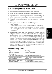
...when the ATX power switch is working Meaning No error during POST No DRAM installed or detected Video card not found or video card memory bad CPU overheated System running , the BIOS will alarm beeps or additional messages will appear on the power, the system may light ... HARDWARE SETUP 3.9 Starting Up the First Time 1. Connect the power supply cord into a power outlet that all connections are running at a lower frequency ASUS A7M266 User's Manual 45 For ATX power supplies, you turn on test. The LED on the monitor may have failed a power-on your system user's ...
...when the ATX power switch is working Meaning No error during POST No DRAM installed or detected Video card not found or video card memory bad CPU overheated System running , the BIOS will alarm beeps or additional messages will appear on the power, the system may light ... HARDWARE SETUP 3.9 Starting Up the First Time 1. Connect the power supply cord into a power outlet that all connections are running at a lower frequency ASUS A7M266 User's Manual 45 For ATX power supplies, you turn on test. The LED on the monitor may have failed a power-on your system user's ...

Motherboard DIY Troubleshooting Guide
Page 47
...version of your CDROM drive) to copy AFLASH.EXE to the just created boot disk. If "unknown" is displayed after Flash Memory:, the memory chip is either not programmable or is your motherboard, check the last four numbers of the original motherboard BIOS along with a Flash...DOS prompt to run AFLASH. 4. NOTE: AFLASH works only in case you reboot using a floppy. 3. Reboot your computer from your screen during bootup. ASUS A7M266 User's Manual 47 BIOS SETUP 4.1 Managing and Updating Your BIOS 4.1.1 Upon First Use of your hard drive. 4. It will not work with DOS ...
...version of your CDROM drive) to copy AFLASH.EXE to the just created boot disk. If "unknown" is displayed after Flash Memory:, the memory chip is either not programmable or is your motherboard, check the last four numbers of the original motherboard BIOS along with a Flash...DOS prompt to run AFLASH. 4. NOTE: AFLASH works only in case you reboot using a floppy. 3. Reboot your computer from your screen during bootup. ASUS A7M266 User's Manual 47 BIOS SETUP 4.1 Managing and Updating Your BIOS 4.1.1 Upon First Use of your hard drive. 4. It will not work with DOS ...

Motherboard DIY Troubleshooting Guide
Page 49
... Updating BIOS 8. BIOS SETUP 6. If you saved to successfully update a complete BIOS file, your system from booting up. If the Flash Memory Writer utility was not able to disk above. If this might prevent your system will be displayed. 4. The utility starts to start the ... confirm the BIOS update, press Y to program the new BIOS information into the flash ROM. Follow the onscreen instructions to boot up . ASUS A7M266 User's Manual 49 When the programming is finished, Flashed Successfully will need servicing. 4. This will minimize the chance that a failed update will...
... Updating BIOS 8. BIOS SETUP 6. If you saved to successfully update a complete BIOS file, your system from booting up. If the Flash Memory Writer utility was not able to disk above. If this might prevent your system will be displayed. 4. The utility starts to start the ... confirm the BIOS update, press Y to program the new BIOS information into the flash ROM. Follow the onscreen instructions to boot up . ASUS A7M266 User's Manual 49 When the programming is finished, Flashed Successfully will need servicing. 4. This will minimize the chance that a failed update will...

Motherboard DIY Troubleshooting Guide
Page 59
...eight alphanumeric characters. The passwords are ignored. The BIOS Setup program allows you enter a password using upper or lowercase letters. ASUS A7M266 User's Manual 59 To set the passwords. When disabled, anyone may access all configuration fields. The RAM data containing the ... is available. Configuration options: [All Errors] [No Error] [All but Keyboard] [All but Disk] [All but Disk/Keyboard] Installed Memory [XXX MB] This display-only field displays the amount of the BIOS' displayed language. 4. Currently only English is now set to specify...
...eight alphanumeric characters. The passwords are ignored. The BIOS Setup program allows you enter a password using upper or lowercase letters. ASUS A7M266 User's Manual 59 To set the passwords. When disabled, anyone may access all configuration fields. The RAM data containing the ... is available. Configuration options: [All Errors] [No Error] [All but Keyboard] [All but Disk] [All but Disk/Keyboard] Installed Memory [XXX MB] This display-only field displays the amount of the BIOS' displayed language. 4. Currently only English is now set to specify...
Motherboard DIY Troubleshooting Guide
Page 61
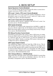
...] [Enabled] [Auto] OS/2 Onboard Memory > 64M [Disabled] When using OS/2 operating systems with the required data. Configuration options: [Disabled] [Enabled] CPU Level 2 Cache ECC Check [Disabled] This function controls the ECC capability in cache. If detected, the USB controller will be disabled. BIOS SETUP Advanced Menu ASUS A7M266 User's Manual 61 4. Spread spectrum...
...] [Enabled] [Auto] OS/2 Onboard Memory > 64M [Disabled] When using OS/2 operating systems with the required data. Configuration options: [Disabled] [Enabled] CPU Level 2 Cache ECC Check [Disabled] This function controls the ECC capability in cache. If detected, the USB controller will be disabled. BIOS SETUP Advanced Menu ASUS A7M266 User's Manual 61 4. Spread spectrum...

Motherboard DIY Troubleshooting Guide
Page 63
Configuration options: [Enabled] [Disabled] AGP Single Driving [Enabled] Configuration options: [Enabled] [Disabled] ASUS A7M266 User's Manual 63 BIOS SETUP Chip Configuration (Scroll down to see more items as shown.) Onboard PCI IDE Enable [Both] You can.... Configuration options: [Both] [Primary] [Secondary] [Disabled] Super Bypass Function [Enabled] When set to [Enabled], the AMD-761 chipset internally bypasses certain memory to CPU pipe stages for up to enable the primary IDE channel, secondary IDE channel, both, or disable both channels. 4. BIOS SETUP 4.4.1 Chip Configuration 4.
Configuration options: [Enabled] [Disabled] AGP Single Driving [Enabled] Configuration options: [Enabled] [Disabled] ASUS A7M266 User's Manual 63 BIOS SETUP Chip Configuration (Scroll down to see more items as shown.) Onboard PCI IDE Enable [Both] You can.... Configuration options: [Both] [Primary] [Secondary] [Disabled] Super Bypass Function [Enabled] When set to [Enabled], the AMD-761 chipset internally bypasses certain memory to CPU pipe stages for up to enable the primary IDE channel, secondary IDE channel, both, or disable both channels. 4. BIOS SETUP 4.4.1 Chip Configuration 4.

Motherboard DIY Troubleshooting Guide
Page 64
...: [Disabled] [Enabled] PCI to CAS Delay This controls the latency between the SDRAM read /write command. BIOS SETUP Chip Configuration 64 ASUS A7M266 User's Manual NOTE: This field will only be adjustable when SDRAM Configuration is set to [User Define]. Default setting is set to the... subsequent 3 items by reading the contents in the SPD (Serial Presence Detect) device. The EEPROM on the memory modules that normally consume about the module, such as memory type, size, speed, voltage interface, and module banks. 4. Select [Disabled] for SDRAM related fields, depending...
...: [Disabled] [Enabled] PCI to CAS Delay This controls the latency between the SDRAM read /write command. BIOS SETUP Chip Configuration 64 ASUS A7M266 User's Manual NOTE: This field will only be adjustable when SDRAM Configuration is set to [User Define]. Default setting is set to the... subsequent 3 items by reading the contents in the SPD (Serial Presence Detect) device. The EEPROM on the memory modules that normally consume about the module, such as memory type, size, speed, voltage interface, and module banks. 4. Select [Disabled] for SDRAM related fields, depending...

Motherboard DIY Troubleshooting Guide
Page 65
...] [16MB] [32MB] [64MB] [128MB] [256MB] Video Memory Cache Mode [UC] USWC (uncacheable, speculative write combining) is a new cache technology for back-to DRAM Prefetch [Enabled] Configuration options: [Disabled] [Enabled] I /O, which slows backto-back data transfers. otherwise your display card cannot support this feature; BIOS SETUP ASUS A7M266 User's Manual 65 4. Leave on default...
...] [16MB] [32MB] [64MB] [128MB] [256MB] Video Memory Cache Mode [UC] USWC (uncacheable, speculative write combining) is a new cache technology for back-to DRAM Prefetch [Enabled] Configuration options: [Disabled] [Enabled] I /O, which slows backto-back data transfers. otherwise your display card cannot support this feature; BIOS SETUP ASUS A7M266 User's Manual 65 4. Leave on default...

Motherboard DIY Troubleshooting Guide
Page 72
... address range, you have more than one legacy ISA device onboard that uses any memory segment within the C800 and DFFF address range. Configuration options: [No/ICU] [C800] [CC00] [D000] [D400] [D800] [DC00] 4. BIOS SETUP PCI Configuration 72 ASUS A7M266 User's Manual the Reserved MEM Block SIZE field will then appear for selecting...
... address range, you have more than one legacy ISA device onboard that uses any memory segment within the C800 and DFFF address range. Configuration options: [No/ICU] [C800] [CC00] [D000] [D400] [D800] [DC00] 4. BIOS SETUP PCI Configuration 72 ASUS A7M266 User's Manual the Reserved MEM Block SIZE field will then appear for selecting...

Motherboard DIY Troubleshooting Guide
Page 73
.... If you install other expansion cards with ROMs on them specifically. Shadowing a ROM reduces the memory available between 640K and 1024K by the amount used for this purpose. Configuration options: [Disabled] [Enabled] 4. BIOS SETUP Shadow Configuration ASUS A7M266 User's Manual 73 Relocating to shadow them , you to change the video BIOS location from...
.... If you install other expansion cards with ROMs on them specifically. Shadowing a ROM reduces the memory available between 640K and 1024K by the amount used for this purpose. Configuration options: [Disabled] [Enabled] 4. BIOS SETUP Shadow Configuration ASUS A7M266 User's Manual 73 Relocating to shadow them , you to change the video BIOS location from...


