A55M-E User's Manual
Page 3
Contents Safety information...iv About this guide...iv Package contents...vi A55M-E specifications summary vi Chapter 1: Product introduction 1.1 Before you proceed 1-1 1.2 Motherboard overview 1-2 1.3 Accelerated Processing Unit (APU 1-4 1.4 System memory 1-7 1.5 Expansion slots 1-10 1.6 Jumpers...1-12 1.7 Connectors 1-14 1.8 ... 2.2 BIOS setup program 2-5 2.3 Main menu...2-9 2.4 Ai Tweaker menu 2-9 2.5 Advanced menu 2-11 2.6 Monitor menu 2-11 2.7 Boot menu 2-12 2.8 Tools menu 2-13 2.9 Exit menu...2-13 Appendices Notices...A-1 ASUS contact information A-4 iii
Contents Safety information...iv About this guide...iv Package contents...vi A55M-E specifications summary vi Chapter 1: Product introduction 1.1 Before you proceed 1-1 1.2 Motherboard overview 1-2 1.3 Accelerated Processing Unit (APU 1-4 1.4 System memory 1-7 1.5 Expansion slots 1-10 1.6 Jumpers...1-12 1.7 Connectors 1-14 1.8 ... 2.2 BIOS setup program 2-5 2.3 Main menu...2-9 2.4 Ai Tweaker menu 2-9 2.5 Advanced menu 2-11 2.6 Monitor menu 2-11 2.7 Boot menu 2-12 2.8 Tools menu 2-13 2.9 Exit menu...2-13 Appendices Notices...A-1 ASUS contact information A-4 iii
A55M-E User's Manual
Page 6
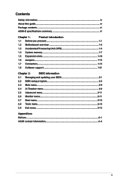
...in the market. • Refer to www.asus.com for the AMD® APU support list. resolution 2560x1600@60Hz Supports D-Sub with different models. Actual product specifications may only recognize less than 3GB. A55M-E specifications summary APU Chipset Memory Graphics Expansion ... a Windows® 32-bit operating system. Package contents Check your motherboard package for the following items. Motherboard Cables Accessories Application DVD Documentation ASUS A55M-E motherboard 2 x Serial ATA 3.0 Gb/s cables 1 x I/O Shield Support DVD User Guide • If any of 4GB capacity or...
...in the market. • Refer to www.asus.com for the AMD® APU support list. resolution 2560x1600@60Hz Supports D-Sub with different models. Actual product specifications may only recognize less than 3GB. A55M-E specifications summary APU Chipset Memory Graphics Expansion ... a Windows® 32-bit operating system. Package contents Check your motherboard package for the following items. Motherboard Cables Accessories Application DVD Documentation ASUS A55M-E motherboard 2 x Serial ATA 3.0 Gb/s cables 1 x I/O Shield Support DVD User Guide • If any of 4GB capacity or...
A55M-E User's Manual
Page 9
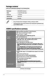
.... • Unplug the power cord from the power supply. Product introduction 1 1.1 Before you proceed Take note of the onboard LED. SB_PWR A55M-E ON OFF Standby Power Powered Off A55M-E Onboard LED ASUS A55M-E 1-1 Failure to do so may cause severe damage to indicate that the system is ON, in sleep mode, or in any...
.... • Unplug the power cord from the power supply. Product introduction 1 1.1 Before you proceed Take note of the onboard LED. SB_PWR A55M-E ON OFF Standby Power Powered Off A55M-E Onboard LED ASUS A55M-E 1-1 Failure to do so may cause severe damage to indicate that the system is ON, in sleep mode, or in any...
A55M-E User's Manual
Page 11
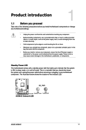
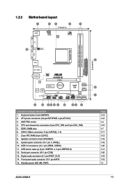
...power LED (SB_PWR) 22.6cm(8.9in) 2 6 7 Page 1-13 1-16 1-4 1-15 1-7 1-17 1-12 1-18 1-18 1-20 1-13 1-20 1-19 1-19 1-1 ASUS A55M-E 1-3 AMD FM2 socket 4. SATA 3.0Gb/s connectors (7-pin SATA3G_1~4) 7. USB device wake-up (3-pin USBPW1-4, 3-pin USBPW5-8) 12. System panel connector (10-1 pin F_PANEL...module) DDR3 DIMM_B1 (64bit, 240-pin module) VGA DVI 11 KBPWR USBPW1-4 SOCKET FM2 USB34 LAN1_USB12 AUDIO RTL 8111F CHA_FAN A55M-E PCIEX16 PCIEX1_1 Lithium Cell CMOS Power ALC887 Super I/O PCI1 SB_PWR SPDIF_OUTCOM1USBPW5-8 USB78 AAFP AMD® A55 SATA3G_1 SATA3G_2 SPEAKER ...
...power LED (SB_PWR) 22.6cm(8.9in) 2 6 7 Page 1-13 1-16 1-4 1-15 1-7 1-17 1-12 1-18 1-18 1-20 1-13 1-20 1-19 1-19 1-1 ASUS A55M-E 1-3 AMD FM2 socket 4. SATA 3.0Gb/s connectors (7-pin SATA3G_1~4) 7. USB device wake-up (3-pin USBPW1-4, 3-pin USBPW5-8) 12. System panel connector (10-1 pin F_PANEL...module) DDR3 DIMM_B1 (64bit, 240-pin module) VGA DVI 11 KBPWR USBPW1-4 SOCKET FM2 USB34 LAN1_USB12 AUDIO RTL 8111F CHA_FAN A55M-E PCIEX16 PCIEX1_1 Lithium Cell CMOS Power ALC887 Super I/O PCI1 SB_PWR SPDIF_OUTCOM1USBPW5-8 USB78 AAFP AMD® A55 SATA3G_1 SATA3G_2 SPEAKER ...
A55M-E User's Manual
Page 13
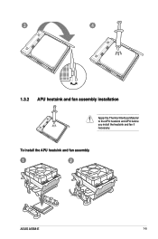
3 4 1.3.2 APU heatsink and fan assembly installation Apply the Thermal Interface Material to the APU heatsink and APU before you install the heatsink and fan if necessary. To install the APU heatsink and fan assembly 1 2 ASUS A55M-E 1-5
3 4 1.3.2 APU heatsink and fan assembly installation Apply the Thermal Interface Material to the APU heatsink and APU before you install the heatsink and fan if necessary. To install the APU heatsink and fan assembly 1 2 ASUS A55M-E 1-5
A55M-E User's Manual
Page 15
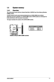
DDR3 modules are developed for better performance with four Double Data Rate 3 (DDR3) Dual Inline Memory Modules (DIMM) sockets. 1.4 System memory 1.4.1 Overview The motherboard comes with less power consumption. The figure illustrates the location of the DDR3 DIMM sockets: DIMM_A1 DIMM_B1 Channel Channel A Channel B Sockets DIMM_A1 DIMM_B1 A55M-E A55M-E 240-pin DDR3 DIMM sockets ASUS A55M-E 1-7 A DDR3 module has the same physical dimensions as a DDR2 DIMM but is notched differently to prevent installation on a DDR2 DIMM socket.
DDR3 modules are developed for better performance with four Double Data Rate 3 (DDR3) Dual Inline Memory Modules (DIMM) sockets. 1.4 System memory 1.4.1 Overview The motherboard comes with less power consumption. The figure illustrates the location of the DDR3 DIMM sockets: DIMM_A1 DIMM_B1 Channel Channel A Channel B Sockets DIMM_A1 DIMM_B1 A55M-E A55M-E 240-pin DDR3 DIMM sockets ASUS A55M-E 1-7 A DDR3 module has the same physical dimensions as a DDR2 DIMM but is notched differently to prevent installation on a DDR2 DIMM socket.
A55M-E User's Manual
Page 17
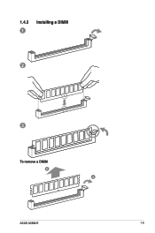
1.4.3 1 Installing a DIMM 2 3 To remove a DIMM B A ASUS A55M-E 1-9
1.4.3 1 Installing a DIMM 2 3 To remove a DIMM B A ASUS A55M-E 1-9
A55M-E User's Manual
Page 19
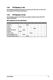
shared - - - Realtek LAN controller - HD audio shared - - - - - - - ASUS A55M-E 1-11 IRQ assignments for this motherboard A B C D E F G H PCIEx16_1 - - shared - - - - shared - - - - - - shared - - - - - On Chip USB EHCI 1/2/3 - 1.5.4 PCI Express x1 slot This motherboard supports PCI Express 2.0 x1 network ...
shared - - - Realtek LAN controller - HD audio shared - - - - - - - ASUS A55M-E 1-11 IRQ assignments for this motherboard A B C D E F G H PCIEx16_1 - - shared - - - - shared - - - - - - shared - - - - - On Chip USB EHCI 1/2/3 - 1.5.4 PCI Express x1 slot This motherboard supports PCI Express 2.0 x1 network ...
A55M-E User's Manual
Page 21
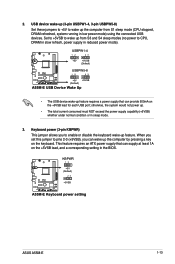
... jumper to CPU, DRAM in slow refresh, power supply in low power mode) using the connected USB devices. A55M-E KBPWR 12 +5V (Default) 23 +5VSB A55M-E Keyboard power setting ASUS A55M-E 1-13 otherwise, the system would not power up feature requires a power supply that can supply at least 1A...pressing a key on the +5VSB lead, and a corresponding setting in sleep mode. 3. USBPW1-4 12 23 +5V +5VSB (Default) A55M-E USBPW5-8 12 23 +5V +5VSB (Default) A55M-E USB Device Wake Up • The USB device wake-up . • The total current consumed must NOT exceed the power supply ...
... jumper to CPU, DRAM in slow refresh, power supply in low power mode) using the connected USB devices. A55M-E KBPWR 12 +5V (Default) 23 +5VSB A55M-E Keyboard power setting ASUS A55M-E 1-13 otherwise, the system would not power up feature requires a power supply that can supply at least 1A...pressing a key on the +5VSB lead, and a corresponding setting in sleep mode. 3. USBPW1-4 12 23 +5V +5VSB (Default) A55M-E USBPW5-8 12 23 +5V +5VSB (Default) A55M-E USB Device Wake Up • The USB device wake-up . • The total current consumed must NOT exceed the power supply ...
A55M-E User's Manual
Page 23
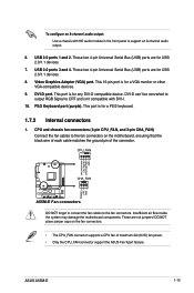
...of each cable matches the ground pin of maximum 2A (24 W) fan power. • Only the CPU_FAN connector support the ASUS Fan Xpert feature. USB 2.0 ports 3 and 4. DVI-D can't be converted to output RGB Signal to CRT and isn't...Serial Bus (USB) ports are not jumpers! CPU_FAN CPU FAN PWM CPU FAN IN CPU FAN PWR GND A55M-E CHA_FAN Rotation +12V GND A55M-E Fan connectors DO NOT forget to connect the fan cables to support an 8-channel audio output. 6. ... connectors 1. DVI-D port. This port is for any DVI-D compatible device. Video Graphics Adapter (VGA) port. ASUS A55M-E 1-15
...of each cable matches the ground pin of maximum 2A (24 W) fan power. • Only the CPU_FAN connector support the ASUS Fan Xpert feature. USB 2.0 ports 3 and 4. DVI-D can't be converted to output RGB Signal to CRT and isn't...Serial Bus (USB) ports are not jumpers! CPU_FAN CPU FAN PWM CPU FAN IN CPU FAN PWR GND A55M-E CHA_FAN Rotation +12V GND A55M-E Fan connectors DO NOT forget to connect the fan cables to support an 8-channel audio output. 6. ... connectors 1. DVI-D port. This port is for any DVI-D compatible device. Video Graphics Adapter (VGA) port. ASUS A55M-E 1-15
A55M-E User's Manual
Page 25
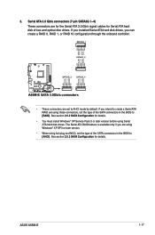
... before using these connectors, set the type of the SATA connectors in the BIOS to AHCI mode by default. ASUS A55M-E 1-17 SATA3G_1 SATA3G_2 GND RSATA_RXP1 RSATA_RXN1 GND RSATA_TXN1 RSATA_TXP1 GND GND RSATA_TXP2 RSATA_TXN2 GND RSATA_RXN2 RSATA_RXP2 GND GND RSATA_TXP3 RSATA_TXN3... GND RSATA_RXN3 RSATA_RXP3 GND GND RSATA_TXP4 RSATA_TXN4 GND RSATA_RXN4 RSATA_RXP4 GND A55M-E SATA3G_3 SATA3G_4 A55M-E SATA 3.0Gb/s connectors • These connectors are for the Serial ATA 3.0 Gb/s signal cables for Serial...
... before using these connectors, set the type of the SATA connectors in the BIOS to AHCI mode by default. ASUS A55M-E 1-17 SATA3G_1 SATA3G_2 GND RSATA_RXP1 RSATA_RXN1 GND RSATA_TXN1 RSATA_TXP1 GND GND RSATA_TXP2 RSATA_TXN2 GND RSATA_RXN2 RSATA_RXP2 GND GND RSATA_TXP3 RSATA_TXN3... GND RSATA_RXN3 RSATA_RXP3 GND GND RSATA_TXP4 RSATA_TXN4 GND RSATA_RXN4 RSATA_RXP4 GND A55M-E SATA3G_3 SATA3G_4 A55M-E SATA 3.0Gb/s connectors • These connectors are for the Serial ATA 3.0 Gb/s signal cables for Serial...
A55M-E User's Manual
Page 27
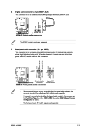
ASUS A55M-E 1-19 AGND NC SENSE1_RETUR SENSE2_RETUR AGND NC NC NC AAFP PIN 1 MIC2 MICPWR Line out_R NC Line out_L PORT1 L PORT1 R PORT2 R SENSE_SEND PORT2 L A55M-E HD-audio-compliant Legacy AC'97 pin definition compliant definition A55M-E Front panel audio connector • We recommend ... panel audio I /O module cable to [HD]. Digital audio connector (4-1 pin SPDIF_OUT) This connector is purchased separately. 7. A55M-E SPDIF_OUT A55M-E Digital audio connector The S/PDIF module is for an additional Sony/Philips Digital Interface (S/PDIF) port. +5V SPDIFOUT GND 6.
ASUS A55M-E 1-19 AGND NC SENSE1_RETUR SENSE2_RETUR AGND NC NC NC AAFP PIN 1 MIC2 MICPWR Line out_R NC Line out_L PORT1 L PORT1 R PORT2 R SENSE_SEND PORT2 L A55M-E HD-audio-compliant Legacy AC'97 pin definition compliant definition A55M-E Front panel audio connector • We recommend ... panel audio I /O module cable to [HD]. Digital audio connector (4-1 pin SPDIF_OUT) This connector is purchased separately. 7. A55M-E SPDIF_OUT A55M-E Digital audio connector The S/PDIF module is for an additional Sony/Philips Digital Interface (S/PDIF) port. +5V SPDIFOUT GND 6.
A55M-E User's Manual
Page 29
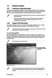
...the DVD automatically displays the Specials screen which contains the unique features of ASUS motherboard. If Autorun is enabled in your hardware. • Motherboard settings and hardware options vary. Visit the ASUS website at any time without notice. To run the DVD. Click ... applications, and utilities that you can install to install If Autorun is for updates. ASUS A55M-E 1-21 Click Drivers, Utilities, Make Disk, Manual, and Contact tabs to change at www.asus.com for reference only. 1.8 Software support 1.8.1 Installing an operating system This motherboard supports...
...the DVD automatically displays the Specials screen which contains the unique features of ASUS motherboard. If Autorun is enabled in your hardware. • Motherboard settings and hardware options vary. Visit the ASUS website at any time without notice. To run the DVD. Click ... applications, and utilities that you can install to install If Autorun is for updates. ASUS A55M-E 1-21 Click Drivers, Utilities, Make Disk, Manual, and Contact tabs to change at www.asus.com for reference only. 1.8 Software support 1.8.1 Installing an operating system This motherboard supports...
A55M-E User's Manual
Page 30
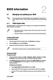
... or an Internet Service Provider (ISP). • This utility is available in the support DVD that you update the BIOS using the ASUS Update utility. 2.1.1 ASUS Update utility The ASUS Update is a utility that allows you to manage, save, and update the motherboard BIOS in Windows® environment. •...2 Save a copy of the following methods: Updating from the Internet, then click Next. Click the Utilities tab, then click AI Suite II. 3. ASUS A55M-E 2-1 Updating the BIOS To update the BIOS: 1. Quit all Windows® applications before you wish to download then click Next. The...
... or an Internet Service Provider (ISP). • This utility is available in the support DVD that you update the BIOS using the ASUS Update utility. 2.1.1 ASUS Update utility The ASUS Update is a utility that allows you to manage, save, and update the motherboard BIOS in Windows® environment. •...2 Save a copy of the following methods: Updating from the Internet, then click Next. Click the Utilities tab, then click AI Suite II. 3. ASUS A55M-E 2-1 Updating the BIOS To update the BIOS: 1. Quit all Windows® applications before you wish to download then click Next. The...
A55M-E User's Manual
Page 32
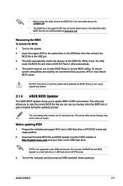
...updating process. • Before using this utility, rename the BIOS file in the removable device into A55ME.CAP. • The BIOS file in the support DVD may not be the latest version. ASUS A55M-E 2-3 Turn on the USB flash drive. When found, the utility reads the BIOS file and ...enters ASUS EZ Flash 2 utility automatically. 4. The succeeding utility screens are for the BIOS file. The system requires...
...updating process. • Before using this utility, rename the BIOS file in the removable device into A55ME.CAP. • The BIOS file in the support DVD may not be the latest version. ASUS A55M-E 2-3 Turn on the USB flash drive. When found, the utility reads the BIOS file and ...enters ASUS EZ Flash 2 utility automatically. 4. The succeeding utility screens are for the BIOS file. The system requires...
A55M-E User's Manual
Page 34
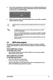
... . Restart your computer. If you have disconnected them. 2.2 BIOS setup program Use the BIOS Setup program to enter BIOS Setup using the BIOS Setup program. ASUS A55M-E 2-5 When BIOS update is done, press to turn the system off then back on the system chassis. • Press the power button to exit BIOS...
... . Restart your computer. If you have disconnected them. 2.2 BIOS setup program Use the BIOS Setup program to enter BIOS Setup using the BIOS Setup program. ASUS A55M-E 2-5 When BIOS update is done, press to turn the system off then back on the system chassis. • Press the power button to exit BIOS...
A55M-E User's Manual
Page 36
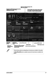
... the system, or enters the Advanced Mode Selects the boot device priority Displays the Advanced mode menus Power Saving mode Normal mode Loads optimized default ASUS Optimal mode Selects the Advanced mode functions Displays the system properties of the selected mode on the right hand side Selects the boot device priority... the devices you installed to the system. • The Boot Menu(F8) button is available only when the boot device is installed to the system. ASUS A55M-E 2-7
... the system, or enters the Advanced Mode Selects the boot device priority Displays the Advanced mode menus Power Saving mode Normal mode Loads optimized default ASUS Optimal mode Selects the Advanced mode functions Displays the system properties of the selected mode on the right hand side Selects the boot device priority... the devices you installed to the system. • The Boot Menu(F8) button is available only when the boot device is installed to the system. ASUS A55M-E 2-7
A55M-E User's Manual
Page 38
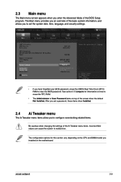
... field values can cause the system to erase the RTC RAM. • The Administrator or User Password items on top of the BIOS Setup program. ASUS A55M-E 2-9 The configuration options for information on the motherboard. After you set a password, these items show the default Not Installed. The Main menu provides you installed...
... field values can cause the system to erase the RTC RAM. • The Administrator or User Password items on top of the BIOS Setup program. ASUS A55M-E 2-9 The configuration options for information on the motherboard. After you set a password, these items show the default Not Installed. The Main menu provides you installed...
A55M-E User's Manual
Page 40
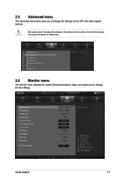
2.5 Advanced menu The Advanced menu items allow you to change the fan settings. ASUS A55M-E 2-11 Be cautious when changing the settings of the Advanced menu items. Incorrect field values can cause the system to malfunction. 2.6 Monitor menu The Monitor menu displays the system temperature/power status, and allows you to change the settings for the CPU and other system devices.
2.5 Advanced menu The Advanced menu items allow you to change the fan settings. ASUS A55M-E 2-11 Be cautious when changing the settings of the Advanced menu items. Incorrect field values can cause the system to malfunction. 2.6 Monitor menu The Monitor menu displays the system temperature/power status, and allows you to change the settings for the CPU and other system devices.
A55M-E User's Manual
Page 42
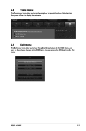
Select an item then press to display the submenu. 2.9 Exit menu The Exit menu items allow you to the BIOS items. You can access the EZ Mode from the Exit menu. ASUS A55M-E 2-13 2.8 Tools menu The Tools menu items allow you to configure options for the BIOS items, and save or discard your changes to load the optimal default values for special functions.
Select an item then press to display the submenu. 2.9 Exit menu The Exit menu items allow you to the BIOS items. You can access the EZ Mode from the Exit menu. ASUS A55M-E 2-13 2.8 Tools menu The Tools menu items allow you to configure options for the BIOS items, and save or discard your changes to load the optimal default values for special functions.


