A55BM-E User's Manual
Page 2
... under the General Public License ("GPL"), under various Free Open Source Software licenses. SPECIFICATIONS AND INFORMATION CONTAINED IN THIS MANUAL ARE FURNISHED FOR INFORMATIONAL USE ONLY, AND ARE SUBJECT TO CHANGE AT ANY TIME WITHOUT NOTICE, AND SHOULD NOT BE CONSTRUED AS A COMMITMENT BY ASUS. Offer to Provide Source Code of reproduction and shipment, which you wish to...
... under the General Public License ("GPL"), under various Free Open Source Software licenses. SPECIFICATIONS AND INFORMATION CONTAINED IN THIS MANUAL ARE FURNISHED FOR INFORMATIONAL USE ONLY, AND ARE SUBJECT TO CHANGE AT ANY TIME WITHOUT NOTICE, AND SHOULD NOT BE CONSTRUED AS A COMMITMENT BY ASUS. Offer to Provide Source Code of reproduction and shipment, which you wish to...

A55BM-E User's Manual
Page 4
... a device. • Before connecting or removing signal cables from the motherboard, ensure that all power cables are unplugged. • Seek professional assistance before the signal cables are also provided. If possible, disconnect all power cables from the existing system before you encounter technical problems with the package. • Before using the product, ensure all the manuals that your power supply is set to change system settings through the BIOS Setup...
... a device. • Before connecting or removing signal cables from the motherboard, ensure that all power cables are unplugged. • Seek professional assistance before the signal cables are also provided. If possible, disconnect all power cables from the existing system before you encounter technical problems with the package. • Before using the product, ensure all the manuals that your power supply is set to change system settings through the BIOS Setup...
A55BM-E User's Manual
Page 6
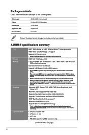
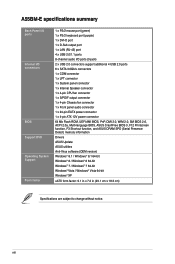
... memory capacity can be supported with max. resolution 2560x1600@60Hz Supports D-Sub with 16GB or above items is damaged or missing, contact your motherboard package for the following items. Motherboard Cables Accessories Application DVD Documentation ASUS A55BM-E motherboard 2 x Serial ATA 3.0 Gb/s cables 1 x I/O Shield Support DVD User Guide If any of 2G Supports AMD® Dual Graphics technology * Refer to http://www.amd.com/us/products/technologies/dual-graphics/ Pages/dual-graphics.aspx#3 for the discrete GPUs which support Dual Graphics technology. 1 x PCIe 3.0/2.0 x16 slot...
... memory capacity can be supported with max. resolution 2560x1600@60Hz Supports D-Sub with 16GB or above items is damaged or missing, contact your motherboard package for the following items. Motherboard Cables Accessories Application DVD Documentation ASUS A55BM-E motherboard 2 x Serial ATA 3.0 Gb/s cables 1 x I/O Shield Support DVD User Guide If any of 2G Supports AMD® Dual Graphics technology * Refer to http://www.amd.com/us/products/technologies/dual-graphics/ Pages/dual-graphics.aspx#3 for the discrete GPUs which support Dual Graphics technology. 1 x PCIe 3.0/2.0 x16 slot...
A55BM-E User's Manual
Page 7
... and short circuit damage prevention ASUS ESD Guards - EPU - ASUS UEFI BIOS ASUS EZ DIY - ASUS CrashFree BIOS 3 - ASUS Fan Xpert - AI Suite 3 - Anti-Surge ASUS Quiet Thermal Solutions - ASUS EZ Flash 2 - A55BM-E specifications summary Storage / RAID LAN Audio USB ASUS unique features AMD® A55 FCH: - 6 x Serial ATA 3.0Gb/s connectors (dark brown) support RAID 0, RAID 1, RAID 10, and JBOD configurations Realtek® 8111G Gigabit LAN controller Realtek® ALC887-VD 8-channel High Definition Audio CODEC • Use a chassis with HD audio module in the front panel...
... and short circuit damage prevention ASUS ESD Guards - EPU - ASUS UEFI BIOS ASUS EZ DIY - ASUS CrashFree BIOS 3 - ASUS Fan Xpert - AI Suite 3 - Anti-Surge ASUS Quiet Thermal Solutions - ASUS EZ Flash 2 - A55BM-E specifications summary Storage / RAID LAN Audio USB ASUS unique features AMD® A55 FCH: - 6 x Serial ATA 3.0Gb/s connectors (dark brown) support RAID 0, RAID 1, RAID 10, and JBOD configurations Realtek® 8111G Gigabit LAN controller Realtek® ALC887-VD 8-channel High Definition Audio CODEC • Use a chassis with HD audio module in the front panel...
A55BM-E User's Manual
Page 8
... System panel connector 1 x Internal Speaker connector 1 x 4-pin CPU fan connector 1 x S/PDIF output connector 1 x 4-pin Chassis fan connector 1 x Front panel audio connector 1 x 24-pin EATX power connector 1 x 4-pin ATX 12V power connector 64 Mb Flash ROM, UEFI AMI BIOS, PnP, DMI 2.0, WfM 2.0, SM BIOS 2.6, ACPI 2.0a, Multi-language BIOS, ASUS CrashFree BIOS 3, F12 Printscreen function, F3 Shortcut function, and ASUS DRAM SPD (Serial Presence Detect) memory information Drivers ASUS Update ASUS utilities Anti-Virus software (OEM version) Windows® 8.1 / Windows® 8.1 64-bit Windows®...
... System panel connector 1 x Internal Speaker connector 1 x 4-pin CPU fan connector 1 x S/PDIF output connector 1 x 4-pin Chassis fan connector 1 x Front panel audio connector 1 x 24-pin EATX power connector 1 x 4-pin ATX 12V power connector 64 Mb Flash ROM, UEFI AMI BIOS, PnP, DMI 2.0, WfM 2.0, SM BIOS 2.6, ACPI 2.0a, Multi-language BIOS, ASUS CrashFree BIOS 3, F12 Printscreen function, F3 Shortcut function, and ASUS DRAM SPD (Serial Presence Detect) memory information Drivers ASUS Update ASUS utilities Anti-Virus software (OEM version) Windows® 8.1 / Windows® 8.1 64-bit Windows®...

A55BM-E User's Manual
Page 11
...pin SPEAKER) 7. USB 2.0 connectors (10-1 pin USB34, USB56) 12. USB device wake-up (3-pin KB_USBPWB) 2. Front panel audio connector (10-1 pin AAFP) ASUS A55BM-E Page 1-13 1-16 1-4 1-15 1-7 1-18 1-17 1-18 1-11 1-1 1-20 1-12 1-21 1-19 1-20 1-19 1-3 Clear RTC RAM (3-pin CLRTC) 10. Standby power LED (SB_PWR) 11. ATX power connectors (24-pin EATXPWR, 4-pin ATX12V) 3. SATA 3.0Gb/s connectors (7-pin SATA3G_1~6) 8. Digital audio connector (4-1 pin SPDIF_OUT) 15. DDR3 DIMM slots 6. Keyboard and USB device wake up (3-pin USBPWF) 13. AMD FM2+ socket 4. Serial port connector...
...pin SPEAKER) 7. USB 2.0 connectors (10-1 pin USB34, USB56) 12. USB device wake-up (3-pin KB_USBPWB) 2. Front panel audio connector (10-1 pin AAFP) ASUS A55BM-E Page 1-13 1-16 1-4 1-15 1-7 1-18 1-17 1-18 1-11 1-1 1-20 1-12 1-21 1-19 1-20 1-19 1-3 Clear RTC RAM (3-pin CLRTC) 10. Standby power LED (SB_PWR) 11. ATX power connectors (24-pin EATXPWR, 4-pin ATX12V) 3. SATA 3.0Gb/s connectors (7-pin SATA3G_1~6) 8. Digital audio connector (4-1 pin SPDIF_OUT) 15. DDR3 DIMM slots 6. Keyboard and USB device wake up (3-pin USBPWF) 13. AMD FM2+ socket 4. Serial port connector...
A55BM-E User's Manual
Page 16
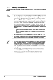
Any excess memory from the higher-sized channel is the standard way of accessing information from the same vendor. Use a 64-bit Windows® OS if you want to section 2.5 Ai Tweaker menu for manual memory frequency adjustment. • For system stability, use of memory, we recommend that you install memory modules of the same version or date code (D/C) from a memory module. For optimal compatibility, we recommend that you do...
Any excess memory from the higher-sized channel is the standard way of accessing information from the same vendor. Use a 64-bit Windows® OS if you want to section 2.5 Ai Tweaker menu for manual memory frequency adjustment. • For system stability, use of memory, we recommend that you install memory modules of the same version or date code (D/C) from a memory module. For optimal compatibility, we recommend that you do...

A55BM-E User's Manual
Page 18
... power cord before adding or removing expansion cards. Align the card connector with it by adjusting the software settings. 1. Turn on the slot. 5. When using PCI cards on BIOS setup. 2. See Chapter 2 for the card. 2. Install the software drivers for later use . Before installing the expansion card, read the documentation that you intend to the chassis with PCI specifications. 1-10 Chapter 1: Product introduction Secure the card to use . 4. Remove the bracket opposite the slot that came with the slot...
... power cord before adding or removing expansion cards. Align the card connector with it by adjusting the software settings. 1. Turn on the slot. 5. When using PCI cards on BIOS setup. 2. See Chapter 2 for the card. 2. Install the software drivers for later use . Before installing the expansion card, read the documentation that you intend to the chassis with PCI specifications. 1-10 Chapter 1: Product introduction Secure the card to use . 4. Remove the bracket opposite the slot that came with the slot...
A55BM-E User's Manual
Page 19
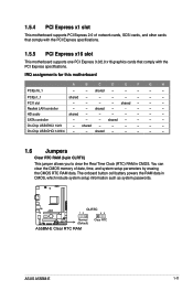
...The onboard button cell battery powers the RAM data in CMOS. shared - - - - - SATA controller - - - shared - - - - - On Chip USB EHCI 1/2/3 - You can clear the CMOS memory of date, time, and system setup parameters by erasing the CMOS RTC RAM data. A55BM-E CLRTC 12 23 Normal (Default) A55BM-E Clear RTC RAM Clear RTC ASUS A55BM-E 1-11 PCI1 slot - - - - shared - - - - 1.5.4 PCI Express x1 slot This motherboard supports PCI Express 2.0 x1 network cards, SCSI cards, and other cards that comply with the PCI Express specifications. 1.5.5 PCI Express x16...
...The onboard button cell battery powers the RAM data in CMOS. shared - - - - - SATA controller - - - shared - - - - - On Chip USB EHCI 1/2/3 - You can clear the CMOS memory of date, time, and system setup parameters by erasing the CMOS RTC RAM data. A55BM-E CLRTC 12 23 Normal (Default) A55BM-E Clear RTC RAM Clear RTC ASUS A55BM-E 1-11 PCI1 slot - - - - shared - - - - 1.5.4 PCI Express x1 slot This motherboard supports PCI Express 2.0 x1 network cards, SCSI cards, and other cards that comply with the PCI Express specifications. 1.5.5 PCI Express x16...
A55BM-E User's Manual
Page 20
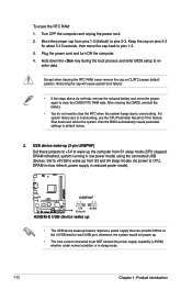
... the BIOS automatically resets parameter settings to wake up the computer from S1 sleep mode (CPU stopped, DRAM refreshed, system running in reduced power mode). After clearing the CMOS, reinstall the battery. • You do not help, remove the onboard battery and move the cap back to CPU, DRAM in slow refresh, power supply in low power mode) using the connected USB devices. Move the jumper cap from S3 and S4 sleep modes (no power to pins 1-2. 3. To erase the RTC RAM: 1. Turn...
... the BIOS automatically resets parameter settings to wake up the computer from S1 sleep mode (CPU stopped, DRAM refreshed, system running in reduced power mode). After clearing the CMOS, reinstall the battery. • You do not help, remove the onboard battery and move the cap back to CPU, DRAM in slow refresh, power supply in low power mode) using the connected USB devices. Move the jumper cap from S3 and S4 sleep modes (no power to pins 1-2. 3. To erase the RTC RAM: 1. Turn...

A55BM-E User's Manual
Page 21
... Network (LAN) through a network hub. KB_USBPWB 12 23 A55BM-E +5V +5VSB (Default) A55BM-E Keyboard and USB device wake up the computer by pressing a key on the +5VSB lead, and a corresponding setting in the BIOS. Video Graphics Adapter (VGA) port. PS/2 Mouse port (green). LAN (RJ-45) port. This port allows Gigabit connection to enable or disable the keyboard and USB device wake-up feature. ASUS A55BM-E 1-13 This port is for a PS/2 mouse. 2. This feature requires an ATX power supply that can wake up 1.7 Connectors 1.7.1 Rear panel connectors...
... Network (LAN) through a network hub. KB_USBPWB 12 23 A55BM-E +5V +5VSB (Default) A55BM-E Keyboard and USB device wake up the computer by pressing a key on the +5VSB lead, and a corresponding setting in the BIOS. Video Graphics Adapter (VGA) port. PS/2 Mouse port (green). LAN (RJ-45) port. This port allows Gigabit connection to enable or disable the keyboard and USB device wake-up feature. ASUS A55BM-E 1-13 This port is for a PS/2 mouse. 2. This feature requires an ATX power supply that can wake up 1.7 Connectors 1.7.1 Rear panel connectors...

A55BM-E User's Manual
Page 22
... Speaker Out Bass/Center Side Speaker Out To configure a 7.1-channel audio output: Use a chassis with DVI-I. 10. These two 4-pin Universal Serial Bus (USB) ports are for USB 2.0/1.1 devices. 8. Line In port (light blue). This port connects to wake up from S5 mode Speed LED Status Description OFF 10Mbps connection ORANGE 100Mbps connection GREEN 1Gbps connection ACT/LINK SPEED LED LED LAN port 4. DVI-D can't be converted to output RGB Signal to CRT and isn't compatible with HD audio module in 2.1, 4.1, 5.1, or 7.1-channel configuration...
... Speaker Out Bass/Center Side Speaker Out To configure a 7.1-channel audio output: Use a chassis with DVI-I. 10. These two 4-pin Universal Serial Bus (USB) ports are for USB 2.0/1.1 devices. 8. Line In port (light blue). This port connects to wake up from S5 mode Speed LED Status Description OFF 10Mbps connection ORANGE 100Mbps connection GREEN 1Gbps connection ACT/LINK SPEED LED LED LAN port 4. DVI-D can't be converted to output RGB Signal to CRT and isn't compatible with HD audio module in 2.1, 4.1, 5.1, or 7.1-channel configuration...
A55BM-E User's Manual
Page 23
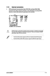
... jumpers! CPU and chassis fan connectors (4-pin CPU_FAN, and 4-pin CHA_FAN) Connect the fan cables to the fan connectors. ASUS A55BM-E 1-15 CPU_FAN CHA_FAN A55BM-E A55BM-E Fan connectors DO NOT forget to connect the fan cables to the fan connectors on the fan connectors. • The CPU_FAN connector supports a CPU fan of the connector. CPU FAN PWM CPU FAN IN CPU FAN PWR GND CHA FAN PWM CHA FAN IN CHA FAN PWR GND 1.7.2 Internal connectors 1. DO NOT place jumper caps on the motherboard, ensuring that the black wire of each cable matches the ground pin...
... jumpers! CPU and chassis fan connectors (4-pin CPU_FAN, and 4-pin CHA_FAN) Connect the fan cables to the fan connectors. ASUS A55BM-E 1-15 CPU_FAN CHA_FAN A55BM-E A55BM-E Fan connectors DO NOT forget to connect the fan cables to the fan connectors on the fan connectors. • The CPU_FAN connector supports a CPU fan of the connector. CPU FAN PWM CPU FAN IN CPU FAN PWR GND CHA FAN PWM CHA FAN IN CHA FAN PWR GND 1.7.2 Internal connectors 1. DO NOT place jumper caps on the motherboard, ensuring that the black wire of each cable matches the ground pin...

A55BM-E User's Manual
Page 25
ASUS A55BM-E 1-17 Serial ATA 3.0 Gb/s connectors (7-pin SATA3G 1~6) These connectors are using Windows® XP SP3 or later version. • When using Serial ATA hard disk drives. If you installed Serial ATA hard disk drives, you are for the Serial ATA 3.0 Gb/s signal cables for Serial ATA hard disk drives and optical disc drives. If you intend to create a Serial ATA RAID set using these connectors, set to [RAID]. • You must install Windows® XP Service Pack 3 or later version before using hot-plug and NCQ, set the type of...
ASUS A55BM-E 1-17 Serial ATA 3.0 Gb/s connectors (7-pin SATA3G 1~6) These connectors are using Windows® XP SP3 or later version. • When using Serial ATA hard disk drives. If you installed Serial ATA hard disk drives, you are for the Serial ATA 3.0 Gb/s signal cables for Serial ATA hard disk drives and optical disc drives. If you intend to create a Serial ATA RAID set using these connectors, set to [RAID]. • You must install Windows® XP Service Pack 3 or later version before using hot-plug and NCQ, set the type of...

A55BM-E User's Manual
Page 27
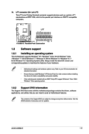
... motherboard high-definition audio capability. • If you want to connect a high definition front panel audio module to this connector, set the Front Panel Type item in the BIOS to this connector. +5V SPDIFOUT GND 6. AGND NC SENSE1_RETUR SENSE2_RETUR AGND NC NC NC AAFP PIN 1 PIN 1 MIC2 MICPWR Line out_R NC Line out_L PORT1 L PORT1 R PORT2 R SENSE_SEND PORT2 L A55BM-E HD-audio-compliant Legacy AC'97 pin definition compliant definition A55BM...
... motherboard high-definition audio capability. • If you want to connect a high definition front panel audio module to this connector, set the Front Panel Type item in the BIOS to this connector. +5V SPDIFOUT GND 6. AGND NC SENSE1_RETUR SENSE2_RETUR AGND NC NC NC AAFP PIN 1 PIN 1 MIC2 MICPWR Line out_R NC Line out_L PORT1 L PORT1 R PORT2 R SENSE_SEND PORT2 L A55BM-E HD-audio-compliant Legacy AC'97 pin definition compliant definition A55BM...
A55BM-E User's Manual
Page 29
... the Support DVD are subject to change at www.asus.com for better compatibility and system stability. • Only motherboards installed with an AMD Trinity APU support Windows® Vista / 64bit Windows® Vista operaing system. 1.8.2 Support DVD information The Support DVD that comes with the motherboard package contains the drivers, software applications, and utilities that you install Windows® XP Service Pack 3 or later versions before installing the drivers for updates. ASUS A55BM-E 1-21 Visit the ASUS website...
... the Support DVD are subject to change at www.asus.com for better compatibility and system stability. • Only motherboards installed with an AMD Trinity APU support Windows® Vista / 64bit Windows® Vista operaing system. 1.8.2 Support DVD information The Support DVD that comes with the motherboard package contains the drivers, software applications, and utilities that you install Windows® XP Service Pack 3 or later versions before installing the drivers for updates. ASUS A55BM-E 1-21 Visit the ASUS website...

A55BM-E User's Manual
Page 31
... 3 main menu bar. Copy the original motherboard BIOS using the ASUS Update utility. 2.1.1 EZ Update EZ Update is a utility that allows you to restore the BIOS in case you can also manually update the saved BIOS and select a boot logo when the system goes into POST. ASUS A55BM-E 2-1 BIOS information 2.1 Managing and updating your BIOS 2 Save a copy of the original motherboard BIOS file to a USB flash disk in the future. With this utlity, you need to automatically update your motherboard's driver, software and firmware Model...
... 3 main menu bar. Copy the original motherboard BIOS using the ASUS Update utility. 2.1.1 EZ Update EZ Update is a utility that allows you to restore the BIOS in case you can also manually update the saved BIOS and select a boot logo when the system goes into POST. ASUS A55BM-E 2-1 BIOS information 2.1 Managing and updating your BIOS 2 Save a copy of the original motherboard BIOS file to a USB flash disk in the future. With this utlity, you need to automatically update your motherboard's driver, software and firmware Model...
A55BM-E User's Manual
Page 32
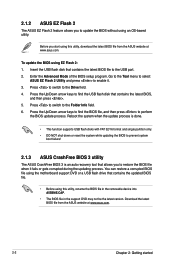
... the Tool menu to select ASUS EZ Flash 2 Utility and press to prevent system boot failure! 2.1.3 ASUS CrashFree BIOS 3 utility The ASUS CrashFree BIOS 3 is an auto recovery tool that contains the updated BIOS file. • Before using EZ Flash 2: 1. Download the latest BIOS file from the ASUS website at www.asus.com. 2-2 Chapter 2: Getting started Enter the Advanced Mode of the BIOS setup program. You can restore a corrupted BIOS file using the motherboard support DVD or a USB flash drive that allows you to perform the BIOS update process.
... the Tool menu to select ASUS EZ Flash 2 Utility and press to prevent system boot failure! 2.1.3 ASUS CrashFree BIOS 3 utility The ASUS CrashFree BIOS 3 is an auto recovery tool that contains the updated BIOS file. • Before using EZ Flash 2: 1. Download the latest BIOS file from the ASUS website at www.asus.com. 2-2 Chapter 2: Getting started Enter the Advanced Mode of the BIOS setup program. You can restore a corrupted BIOS file using the motherboard support DVD or a USB flash drive that allows you to perform the BIOS update process.

A55BM-E User's Manual
Page 33
... system boot failure! 2.1.4 ASUS BIOS Updater The ASUS BIOS Updater allows you can use as shown. This utility also allows you to copy the current BIOS file that you to enter BIOS Setup to a hard disk drive or USB flash drive in DOS environment. Do not save them on the system. 2. Turn off the computer and disconnect all SATA hard disk drives (optional). Insert the support DVD to the optical drive or the USB flash drive that contains the BIOS file to load default BIOS values. The succeeding utility screens...
... system boot failure! 2.1.4 ASUS BIOS Updater The ASUS BIOS Updater allows you can use as shown. This utility also allows you to copy the current BIOS file that you to enter BIOS Setup to a hard disk drive or USB flash drive in DOS environment. Do not save them on the system. 2. Turn off the computer and disconnect all SATA hard disk drives (optional). Insert the support DVD to the optical drive or the USB flash drive that contains the BIOS file to load default BIOS values. The succeeding utility screens...

A55BM-E User's Manual
Page 35
... updating the BIOS to prevent system boot failure! • For BIOS Updater version 1.30 or later, the utility automatically exits to the DOS prompt after POST: • Press ++ simultaneously. • Press the reset button on the system chassis. • Press the power button to ensure system compatibility and stability. Restart your computer. The BIOS screens include navigation keys and brief online help to enter BIOS Setup using the BIOS Setup program. ASUS A55BM-E 2-5 Entering BIOS Setup at startup To enter BIOS Setup...
... updating the BIOS to prevent system boot failure! • For BIOS Updater version 1.30 or later, the utility automatically exits to the DOS prompt after POST: • Press ++ simultaneously. • Press the reset button on the system chassis. • Press the power button to ensure system compatibility and stability. Restart your computer. The BIOS screens include navigation keys and brief online help to enter BIOS Setup using the BIOS Setup program. ASUS A55BM-E 2-5 Entering BIOS Setup at startup To enter BIOS Setup...


