Owners Manual
Page 23
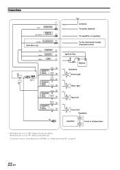
... from Subwoofer. For details on how to set to ON/OFF, see "Subwoofer On and Off" on page 16. 22-EN Connections 1 Blue POWER ANT 2 REMOTE Blue/White TURN-ON 3 Orange ILLUMINATION 4 (CDE-9846 only) Red IGNITION 5 Yellow BATTERY 6 Black GND 7 ~ 8 Gray 9 SPEAKER RIGHT FRONT Gray/ Black !
... from Subwoofer. For details on how to set to ON/OFF, see "Subwoofer On and Off" on page 16. 22-EN Connections 1 Blue POWER ANT 2 REMOTE Blue/White TURN-ON 3 Orange ILLUMINATION 4 (CDE-9846 only) Red IGNITION 5 Yellow BATTERY 6 Black GND 7 ~ 8 Gray 9 SPEAKER RIGHT FRONT Gray/ Black !
Owners Manual
Page 24
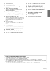
...securely fastened using the sheet metal screw provided. 8 Power Supply Connector 9 Right Front (+) Speaker Output Lead (Gray) ! Your Alpine dealer carries various Alpine noise suppressors, contact them for further information. 23-EN Make sure the connection is made to bare metal and is left. .... 3 Remote Turn-On Lead (Blue/White) Connect this lead to a good chassis ground on lead of your dealer for further information. • Your Alpine dealer knows best about noise prevention measures so consult your amplifier or signal processor. 4 Illumination Lead (Orange) (CDE-9846 only) This...
...securely fastened using the sheet metal screw provided. 8 Power Supply Connector 9 Right Front (+) Speaker Output Lead (Gray) ! Your Alpine dealer carries various Alpine noise suppressors, contact them for further information. 23-EN Make sure the connection is made to bare metal and is left. .... 3 Remote Turn-On Lead (Blue/White) Connect this lead to a good chassis ground on lead of your dealer for further information. • Your Alpine dealer knows best about noise prevention measures so consult your amplifier or signal processor. 4 Illumination Lead (Orange) (CDE-9846 only) This...


