
Acer X203H Service Guide
Page 7
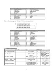
... ~ 70KHz √ Power cord Color: Black Length: 1800 +/- 50 √ mm Depends on panel source Depends on panel source 3.2.2 Signal interface Item Condition Signal Cable 15-pin D-Sub 24-pin DVI-D Pin assignment Analog input 15-pin D-sub connector 24-pin DVI-D connector 19-pin HDMI connector... Signal type Level Impedance Signal type Sync input Digital input Level Impedance Sync Pulse Width (SPW) Level Impedance Spec Color: Black Length: 1800 +/- 30 mm Color...
... ~ 70KHz √ Power cord Color: Black Length: 1800 +/- 50 √ mm Depends on panel source Depends on panel source 3.2.2 Signal interface Item Condition Signal Cable 15-pin D-Sub 24-pin DVI-D Pin assignment Analog input 15-pin D-sub connector 24-pin DVI-D connector 19-pin HDMI connector... Signal type Level Impedance Signal type Sync input Digital input Level Impedance Sync Pulse Width (SPW) Level Impedance Spec Color: Black Length: 1800 +/- 30 mm Color...
Acer X203H Service Guide
Page 8
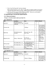
... < 5 ms (50% of minimum pixel √ clock period) < 5% final full-scale value √ < 12% of 24-pin DVI-D connector is as below, Pin Signal Assignment 1 TMDS RX2- 2 TMDS RX2+ 3 TMDS Ground 4 Floating 5 Floating 6 DDC Clock 7 DDC Data 8 Floating 9 TMDS RX1- 10 TMDS RX1+ 11 TMDS Ground...analog and digital inputs 1600x900 @ 60Hz (max. Resolution Rise time + Fall time Settling Time after overshoot /undershoot Overshoot/Undershoot Pin Signal Assignment 13 Floating 14 +5V Power 15 Ground 16 Hot Plug Detect 17 TMDS RX0- 18 TMDS RX0+ 19 TMDS Ground 20...
... < 5 ms (50% of minimum pixel √ clock period) < 5% final full-scale value √ < 12% of 24-pin DVI-D connector is as below, Pin Signal Assignment 1 TMDS RX2- 2 TMDS RX2+ 3 TMDS Ground 4 Floating 5 Floating 6 DDC Clock 7 DDC Data 8 Floating 9 TMDS RX1- 10 TMDS RX1+ 11 TMDS Ground...analog and digital inputs 1600x900 @ 60Hz (max. Resolution Rise time + Fall time Settling Time after overshoot /undershoot Overshoot/Undershoot Pin Signal Assignment 13 Floating 14 +5V Power 15 Ground 16 Hot Plug Detect 17 TMDS RX0- 18 TMDS RX0+ 19 TMDS Ground 20...
Acer X203H Service Guide
Page 10
..., Brightness at 100, Color at User preset. If Hf /Vf is Black and showing "Input Not Supported" warning message. (HDMI supports 50Hz for PAL video signals.) 2. Show "Input Not Supported" warning message.
..., Brightness at 100, Color at User preset. If Hf /Vf is Black and showing "Input Not Supported" warning message. (HDMI supports 50Hz for PAL video signals.) 2. Show "Input Not Supported" warning message.
Acer X203H Service Guide
Page 36
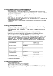
...-in Mode" tag and select "On" to any preset modes, pattern 41(full white color pattern) with a D-sub signal cable. 3. Move cursor into monitor 1. Runs the writing program to monitor with Analog signals from Chroma video pattern generator. (it is by manually and must be used to adjust RED, GREEN, BLUE value... this monitor and check its circuit board or wire/cable connection. 5.1.4 Color temperature adjustment 1. Writing EDID data into "Burn-in mode. 4. Setup a PC with Analog signals from Chroma video pattern generator. 2.
...-in Mode" tag and select "On" to any preset modes, pattern 41(full white color pattern) with a D-sub signal cable. 3. Move cursor into monitor 1. Runs the writing program to monitor with Analog signals from Chroma video pattern generator. (it is by manually and must be used to adjust RED, GREEN, BLUE value... this monitor and check its circuit board or wire/cable connection. 5.1.4 Color temperature adjustment 1. Writing EDID data into "Burn-in mode. 4. Setup a PC with Analog signals from Chroma video pattern generator. 2.
Acer X203H Service Guide
Page 38
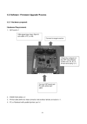
Printer cable (with printer port cable 2. 5.2 Software / Firmware Upgrade Process 5.2.1 Hardware prepared: Hardware Requirement: 1. DSUB VGA cables x 2 3. Connect to target monitor Check the Jumpers on the ISP Circuit Board (make sure J5, J6, J7, J8 are set at ping 1,2 ) Connect ISP board and PC with one male connector and another female connector) x 1. 4. ISP board x 1 VGA signal input from 15pin Dsub cable of PC or NB. PC or Notebook with parallel (printer) port x1. - 38 -
Printer cable (with printer port cable 2. 5.2 Software / Firmware Upgrade Process 5.2.1 Hardware prepared: Hardware Requirement: 1. DSUB VGA cables x 2 3. Connect to target monitor Check the Jumpers on the ISP Circuit Board (make sure J5, J6, J7, J8 are set at ping 1,2 ) Connect ISP board and PC with one male connector and another female connector) x 1. 4. ISP board x 1 VGA signal input from 15pin Dsub cable of PC or NB. PC or Notebook with parallel (printer) port x1. - 38 -
Acer X203H Service Guide
Page 41
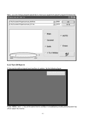
As the following figure ENTER and RIGHT to Burn In Off Press "MENU" and ">" key at the same time to meet your equipment speed if program firmware fail. 5.2.3 Turn Off Burn In IF the monitor without signal input has Burn In pattern. Note: you can change program speed bar to exit Burn in mode(factory mode),and soft power key off/on restart the monitor. - 41 -
As the following figure ENTER and RIGHT to Burn In Off Press "MENU" and ">" key at the same time to meet your equipment speed if program firmware fail. 5.2.3 Turn Off Burn In IF the monitor without signal input has Burn In pattern. Note: you can change program speed bar to exit Burn in mode(factory mode),and soft power key off/on restart the monitor. - 41 -
Acer X203H Service Guide
Page 57
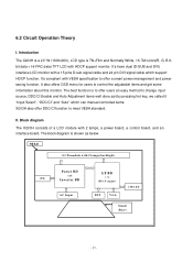
... DVI VGA St a n d (B ase) - 57 - It's have dual (D-SUB and DVI) interface LCD monitor with a 15 pins D-sub signal cable and 24 pin DVI signal cable which can manual controlled items. X203H also offer DDC/CI function to change input source, DDC/CI Enable and Auto Adjustment items well done just by...and SPK Inverter BD I . II. It also offers OSD menu for users to offer a smart power management and power saving function. Block diagram The X203H consists of a LCD module with VESA specification to control the adjustable items and get some information about this monitor. Introduction The...
... DVI VGA St a n d (B ase) - 57 - It's have dual (D-SUB and DVI) interface LCD monitor with a 15 pins D-sub signal cable and 24 pin DVI signal cable which can manual controlled items. X203H also offer DDC/CI function to change input source, DDC/CI Enable and Auto Adjustment items well done just by...and SPK Inverter BD I . II. It also offers OSD menu for users to offer a smart power management and power saving function. Block diagram The X203H consists of a LCD module with VESA specification to control the adjustable items and get some information about this monitor. Introduction The...
Acer X203H Service Guide
Page 58
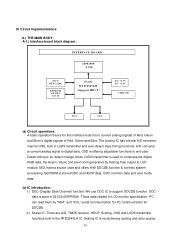
... There are A/D, TMDS receiver, HDCP, Scaling, OSD and LVDS transmitter functions built-in 24C02 (EEPROM). Detect timing is to convert analog signals of Red, Green and Blue to LCD monitor specification. MCU stores source code and offers H/W DDC2Bi function & controls system processing. Those data...Vsync and pixel clock generated by "SDA" and "SCL" serial communication for I²C communication for detect change mode. OSD is convert analog signal to end-user. The scaling IC has internal A/D converter, internal OSD, built in LVDS transmitter and auto-detect input timing functions. III...
... There are A/D, TMDS receiver, HDCP, Scaling, OSD and LVDS transmitter functions built-in 24C02 (EEPROM). Detect timing is to convert analog signals of Red, Green and Blue to LCD monitor specification. MCU stores source code and offers H/W DDC2Bi function & controls system processing. Those data...Vsync and pixel clock generated by "SDA" and "SCL" serial communication for I²C communication for detect change mode. OSD is convert analog signal to end-user. The scaling IC has internal A/D converter, internal OSD, built in LVDS transmitter and auto-detect input timing functions. III...
User Manual
Page 17
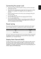
...example, supported resolutions and corresponding timing. Mode On Power saving LED light Blue Amber The power saving mode will be kept until a control signal has been detected or the keyboard or mouse is activated. English Connecting the power cord • Check first to make installation easier, ...so long as indicated by the control signal from "power saving" mode back to "on" is around 3 seconds. Power saving The monitor will be switched to "power saving" mode...
...example, supported resolutions and corresponding timing. Mode On Power saving LED light Blue Amber The power saving mode will be kept until a control signal has been detected or the keyboard or mouse is activated. English Connecting the power cord • Check first to make installation easier, ...so long as indicated by the control signal from "power saving" mode back to "on" is around 3 seconds. Power saving The monitor will be switched to "power saving" mode...
User Manual
Page 19
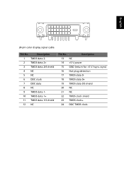
Description 1 TMDS data 2- 2 TMDS data 2+ 3 TMDS data 2/4 shield 4 NC 5 NC 6 DDC clock 7 DDC data 8 NC 9 TMDS data 1- 10 TMDS data 1+ 11 TMDS data 1/3 shield 12 NC PIN No. Description 13 NC 14 +5 V power 15 GND (return for +5 V hsync.vsync) 16 Hot-plug detection 17 TMDS data 0- 18 TMDS data 0+ 19 TMDS data 0/5 shield 20 NC 21 NC 22 TMDS clock shield 23 TMDS clock+ 24 DDC TMDS clock- English 24-pin color display signal cable PIN No.
Description 1 TMDS data 2- 2 TMDS data 2+ 3 TMDS data 2/4 shield 4 NC 5 NC 6 DDC clock 7 DDC data 8 NC 9 TMDS data 1- 10 TMDS data 1+ 11 TMDS data 1/3 shield 12 NC PIN No. Description 13 NC 14 +5 V power 15 GND (return for +5 V hsync.vsync) 16 Hot-plug detection 17 TMDS data 0- 18 TMDS data 0+ 19 TMDS data 0/5 shield 20 NC 21 NC 22 TMDS clock shield 23 TMDS clock+ 24 DDC TMDS clock- English 24-pin color display signal cable PIN No.
User Manual
Page 27
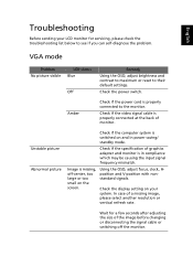
... is properly connected to see if you can self-diagnose the problem. Using the OSD, adjust focus, clock, Hposition and V-position with nonstandard signals. Check the power switch. Amber Check if the power cord is properly connected at the back of a missing image, please select another resolution or vertical ... OSD, adjust brightness and contrast to maximum or reset to their default settings. Check if the specification of the image before changing or disconnecting the signal cable or switching off -center, too large or too small on and in compliance which may be causing the input...
... is properly connected to see if you can self-diagnose the problem. Using the OSD, adjust focus, clock, Hposition and V-position with nonstandard signals. Check the power switch. Amber Check if the power cord is properly connected at the back of a missing image, please select another resolution or vertical ... OSD, adjust brightness and contrast to maximum or reset to their default settings. Check if the specification of the image before changing or disconnecting the signal cable or switching off -center, too large or too small on and in compliance which may be causing the input...
User Manual
Page 28
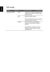
Amber Check if the AC power cord is properly connected at the back of monitor. Check if the video signal cable is properly connected to their default settings. Check the power switch. Check that the computer system is switched on and in power saving/ standby mode. English DVI mode Problem No picture visible LED status Blue Off Remedy Using the OSD, adjust brightness and contrast to maximum or reset to the monitor.
Amber Check if the AC power cord is properly connected at the back of monitor. Check if the video signal cable is properly connected to their default settings. Check the power switch. Check that the computer system is switched on and in power saving/ standby mode. English DVI mode Problem No picture visible LED status Blue Off Remedy Using the OSD, adjust brightness and contrast to maximum or reset to the monitor.


