Aspire M5620 Service Guide
Page 6
... Front Panel 14 VeritonT661/M661/S661 Rear Panel 15 Hardware Specifications and Configurations 16 Power Management Function (ACPI support function 22 Chapter 2 System Utilities 23 Entering Setup 24 Product Information 26 Standard CMOS Features 27 Advanced BIOS Features 30 Integrated Peripherals 34 Power Management 41 PnP/PCI Configuration 44 PC Health Status 46 Frequency/Voltage Control 47 Load Default Settings 49 Set Supervisor/User Password 50 Save & Exit Setup 52 Exit Without Saving 53 Chapter 3 Machine Disassembly and Replacement...
... Front Panel 14 VeritonT661/M661/S661 Rear Panel 15 Hardware Specifications and Configurations 16 Power Management Function (ACPI support function 22 Chapter 2 System Utilities 23 Entering Setup 24 Product Information 26 Standard CMOS Features 27 Advanced BIOS Features 30 Integrated Peripherals 34 Power Management 41 PnP/PCI Configuration 44 PC Health Status 46 Frequency/Voltage Control 47 Load Default Settings 49 Set Supervisor/User Password 50 Save & Exit Setup 52 Exit Without Saving 53 Chapter 3 Machine Disassembly and Replacement...
Aspire M5620 Service Guide
Page 22
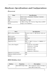
Hardware Specifications and Configurations Processor Item Type Socket FSB Minimum operating speed Specification Intel / Conroe / Kensfield / Wolfdale / Yorkfield LGA 775 pin 800/1066 /1333 MHz 0 MHz (If Stop CPU Clock in Sleep State in BIOS Setup is set to Enabled.) BIOS Item BIOS code programmer BIOS version BIOS ROM type BIOS ROM size Support protocol Device Boot Support Support to LS-120 drive Support to BIOS boot block feature Specification Phoenix Award or AMI Kernel with Acer skin V6.0 SPI Flash 16Mb PXE 2.1 DMI V.2.0(s)or 2.1 SMBIOS 2.5 ACPI...
Hardware Specifications and Configurations Processor Item Type Socket FSB Minimum operating speed Specification Intel / Conroe / Kensfield / Wolfdale / Yorkfield LGA 775 pin 800/1066 /1333 MHz 0 MHz (If Stop CPU Clock in Sleep State in BIOS Setup is set to Enabled.) BIOS Item BIOS code programmer BIOS version BIOS ROM type BIOS ROM size Support protocol Device Boot Support Support to LS-120 drive Support to BIOS boot block feature Specification Phoenix Award or AMI Kernel with Acer skin V6.0 SPI Flash 16Mb PXE 2.1 DMI V.2.0(s)or 2.1 SMBIOS 2.5 ACPI...
Aspire M5620 Service Guide
Page 35
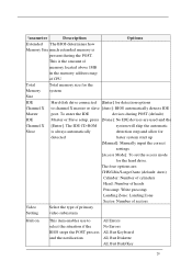
... start up [Manual]: Manually input the correct settings [Access Mode]: To set the access mode for detection options Channel X to select the situation if the BIOS stops the POST process and the notification All Errors No Errors All, But Keyboard All, But Diskette All, But Disk/Key 29 This is the amount of memory located above 1MB in the memory address map of primary Setting video subsystem Halt on This item enables use...
... start up [Manual]: Manually input the correct settings [Access Mode]: To set the access mode for detection options Channel X to select the situation if the BIOS stops the POST process and the notification All Errors No Errors All, But Keyboard All, But Diskette All, But Disk/Key 29 This is the amount of memory located above 1MB in the memory address map of primary Setting video subsystem Halt on This item enables use...
Aspire M5620 Service Guide
Page 37
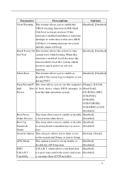
... self-test function. APIC Mode This option is used to set keyboard is number keys or arrow [Disabled] Status keys Security Option This category allows you to see the sequence [Floppy], [LS120], hird Boot of boot device where BIOS attempts to [Hard Disk], Device load the disk operation system. [CD-ROM], [ZIP], [USB-FDD], [USB-ZIP], [USB-CDROM], [USB-HDD], [LAN], [Disabled] Boot From This item allows user to enable or disable [Enabled], Other Devices to boot from other device [Disabled] Boot Up This item allows user to enable or disable [Enabled...
... self-test function. APIC Mode This option is used to set keyboard is number keys or arrow [Disabled] Status keys Security Option This category allows you to see the sequence [Floppy], [LS120], hird Boot of boot device where BIOS attempts to [Hard Disk], Device load the disk operation system. [CD-ROM], [ZIP], [USB-FDD], [USB-ZIP], [USB-CDROM], [USB-HDD], [LAN], [Disabled] Boot From This item allows user to enable or disable [Enabled], Other Devices to boot from other device [Disabled] Boot Up This item allows user to enable or disable [Enabled...
Aspire M5620 Service Guide
Page 42
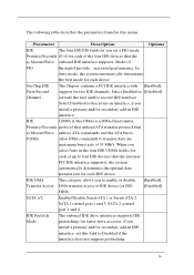
... Master/Slave utilizes ATA commands and the ATA bus to UDMA allow DMA commands to enable or disable [Enabled], Transfer Access DMA transfer access of 33 MB/s. Modes 0 PIO through 4 provide increased performance. IDE DMA This category allows you install a primary and/or secondary add-in the four IDE UDMA fields (for each device. SATA 1 control port 1 and 3, SATA 2 control port 2 and 4. Parameter Description Options IDE The...
... Master/Slave utilizes ATA commands and the ATA bus to UDMA allow DMA commands to enable or disable [Enabled], Transfer Access DMA transfer access of 33 MB/s. Modes 0 PIO through 4 provide increased performance. IDE DMA This category allows you install a primary and/or secondary add-in the four IDE UDMA fields (for each device. SATA 1 control port 1 and 3, SATA 2 control port 2 and 4. Parameter Description Options IDE The...
Aspire M5620 Service Guide
Page 44
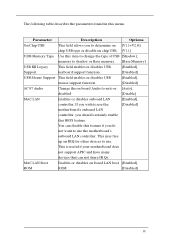
... other devices to use the [Disabled] motherboard's onboard LAN controller, you should certainly enable this feature if you to determine on [V1.1+V2.0], chip USB type or disable on chip USB. [V1.1] UDB Memory Type Use this item to change the type of USB [Shadow], memory to shadow or Base memory. [Base Memory] USB KB Legacy This field enables or disables USB [Enabled], Support keyboard support function. [Disabled] USB Mouse Support This field enables or disables USB [Enabled], mouse support function. [Disabled] AC 97 Audio Change the on board LAN boot [Enabled], ROM ROM...
... other devices to use the [Disabled] motherboard's onboard LAN controller, you should certainly enable this feature if you to determine on [V1.1+V2.0], chip USB type or disable on chip USB. [V1.1] UDB Memory Type Use this item to change the type of USB [Shadow], memory to shadow or Base memory. [Base Memory] USB KB Legacy This field enables or disables USB [Enabled], Support keyboard support function. [Disabled] USB Mouse Support This field enables or disables USB [Enabled], mouse support function. [Disabled] AC 97 Audio Change the on board LAN boot [Enabled], ROM ROM...

Aspire M5620 Service Guide
Page 46
... the IR device connected to manually set the DMA DMA channel for ECP mode 40 Controller controller (FDC) installed on the system board [Disabled] and you install an add-in FDC or the system has no floppy drive, select Disabled in one direction only at a time. Half-duplex mode permits transmission in this field. If you wish to use it. Parameter Description Options Onboard FDC Select Enabled if...
... the IR device connected to manually set the DMA DMA channel for ECP mode 40 Controller controller (FDC) installed on the system board [Disabled] and you install an add-in FDC or the system has no floppy drive, select Disabled in one direction only at a time. Half-duplex mode permits transmission in this field. If you wish to use it. Parameter Description Options Onboard FDC Select Enabled if...
Aspire M5620 Service Guide
Page 51
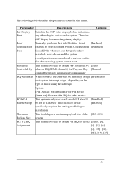
... operating system cannot boot Resources This item allows user to assign PCI IRQ for Plug and Play [Manual] compatible devices automatically or manually IRQ Resources When resource are controlled by manually, assign [Press Enter] each system interrupt a type , depending on the system. It should [Disabled], Palette Snoop be left at "Disabled" unless a video device [Enabled] specifically requires the setting enabled upon installation. Maximum This field displays maximum payload size of device using the interrupt. PCI/VGA...
... operating system cannot boot Resources This item allows user to assign PCI IRQ for Plug and Play [Manual] compatible devices automatically or manually IRQ Resources When resource are controlled by manually, assign [Press Enter] each system interrupt a type , depending on the system. It should [Disabled], Palette Snoop be left at "Disabled" unless a video device [Enabled] specifically requires the setting enabled upon installation. Maximum This field displays maximum payload size of device using the interrupt. PCI/VGA...
Intel Matrix Storage and RAID
Page 9
... your hard disk drives are needed drive ordering. Intel Matrix Storage Manager Quick Guide for most RAID functions. You may not function properly if your screen saver and power-management options such as auto-shutdown, auto-hibernate and auto-standby. The HDD password feature will risk data loss. Warnings and reminders A. Using the Intel® Matrix Storage Console in Windows for Acer Selected Veriton PC V1.1 3. D. Before enabling RAID on...
... your hard disk drives are needed drive ordering. Intel Matrix Storage Manager Quick Guide for most RAID functions. You may not function properly if your screen saver and power-management options such as auto-shutdown, auto-hibernate and auto-standby. The HDD password feature will risk data loss. Warnings and reminders A. Using the Intel® Matrix Storage Console in Windows for Acer Selected Veriton PC V1.1 3. D. Before enabling RAID on...
Intel Matrix Storage and RAID
Page 17
... setup package obtained from a CD-ROM or from the Internet. Open the Intel Matrix Storage Manager from the Start Menu and select Create RAID Volume from Existing Hard Drive from a single-drive non-RAID configuration to or greater than the capacity of the hard drive already in section 6.1. After the migration is complete, reboot the system. Note the serial number of the hard drive being used as the source hard drive for Acer Selected Veriton...
... setup package obtained from a CD-ROM or from the Internet. Open the Intel Matrix Storage Manager from the Start Menu and select Create RAID Volume from Existing Hard Drive from a single-drive non-RAID configuration to or greater than the capacity of the hard drive already in section 6.1. After the migration is complete, reboot the system. Note the serial number of the hard drive being used as the source hard drive for Acer Selected Veriton...
Intel Matrix Storage and RAID
Page 18
... Existing Hard Drive Wizard. Configuring an existing HDD as the source hard drive when initiating the migration. 2. Boot to Windows, install the Intel Matrix Storage Manager software, if not already installed (it as a RAID0 or RAID1 volume If you are booting from the Internet. Select Create RAID Volume from Existing Hard Drive from the Start Menu. 5. Follow the instructions as the source hard drive for Acer Selected Veriton PC V1.1 6. Note the serial number of the SATA hard drive...
... Existing Hard Drive Wizard. Configuring an existing HDD as the source hard drive when initiating the migration. 2. Boot to Windows, install the Intel Matrix Storage Manager software, if not already installed (it as a RAID0 or RAID1 volume If you are booting from the Internet. Select Create RAID Volume from Existing Hard Drive from the Start Menu. 5. Follow the instructions as the source hard drive for Acer Selected Veriton PC V1.1 6. Note the serial number of the SATA hard drive...
Intel Matrix Storage and RAID
Page 20
... user will be installed before installing Windows XP on a floppy disk You can download the RAID driver from the Acer website or Acer Resource CD. The Intel Matrix Storage Manager AHCI driver can be installed over Vista's native AHCI driver. 8.1 Build the RAID driver on a RAID volume or when in your local drive. 2. Format the disk. Write data to exit. 6. On a system running Windows, download the application f6flpy32.exe (for 32-bit operating system...
... user will be installed before installing Windows XP on a floppy disk You can download the RAID driver from the Acer website or Acer Resource CD. The Intel Matrix Storage Manager AHCI driver can be installed over Vista's native AHCI driver. 8.1 Build the RAID driver on a RAID volume or when in your local drive. 2. Format the disk. Write data to exit. 6. On a system running Windows, download the application f6flpy32.exe (for 32-bit operating system...

Veriton M661/T661/S661 Series User's Guide - EN
Page 8
... panel 2 Optical drive 3 Taking care of your CDs and DVDs 3 2 Setting up your computer 5 Arranging a comfortable work area 6 Positioning your monitor 6 Positioning your keyboard 6 Positioning your mouse 6 Connecting peripherals 6 Connecting your mouse and keyboard 7 USB interface 7 PS/2 interface 7 Connecting a monitor 7 Connecting the power cable 7 Turning on your computer 8 Turning off your computer 8 3 Upgrading your computer 9 Installation precautions 10 ESD precautions 10 Preinstallation instructions 10 Post-installation instructions 11 Opening...
... panel 2 Optical drive 3 Taking care of your CDs and DVDs 3 2 Setting up your computer 5 Arranging a comfortable work area 6 Positioning your monitor 6 Positioning your keyboard 6 Positioning your mouse 6 Connecting peripherals 6 Connecting your mouse and keyboard 7 USB interface 7 PS/2 interface 7 Connecting a monitor 7 Connecting the power cable 7 Turning on your computer 8 Turning off your computer 8 3 Upgrading your computer 9 Installation precautions 10 ESD precautions 10 Preinstallation instructions 10 Post-installation instructions 11 Opening...
Veriton M661/T661/S661 Series User's Guide - EN
Page 11
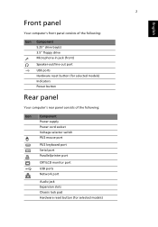
... English Front panel Your computer's front panel consists of the following: Icon Component 5.25" drive bay(s) 3.5" floppy drive Microphone-in jack (front) Speaker-out/line-out port USB ports Hardware reset button (for selected models) Indicators Power button Rear panel Your computer's rear panel consists of the following: Icon Component Power supply Power cord socket Voltage selector switch PS/2 mouse port PS/2 keyboard port Serial port Parallel/printer port CRT/LCD monitor port USB ports Network port Audio jack Expansion slots Chassis lock pad Hardware reset button (for selected...
... English Front panel Your computer's front panel consists of the following: Icon Component 5.25" drive bay(s) 3.5" floppy drive Microphone-in jack (front) Speaker-out/line-out port USB ports Hardware reset button (for selected models) Indicators Power button Rear panel Your computer's rear panel consists of the following: Icon Component Power supply Power cord socket Voltage selector switch PS/2 mouse port PS/2 keyboard port Serial port Parallel/printer port CRT/LCD monitor port USB ports Network port Audio jack Expansion slots Chassis lock pad Hardware reset button (for selected...
Veriton M661/T661/S661 Series User's Guide - EN
Page 16
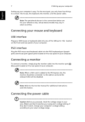
... and rear panels of your computer. Note: The peripherals shown in the connections below are for additional instructions and information. located PS/2 interface Plug the PS/2 mouse and keyboard cable into any of the USB ports on the rear panel of your computer . Connecting a monitor To connect a monitor, simply plug the monitor cable into the monitor port (blue port) located on card and the onboard VGA will be disabled. Actual device models may vary in your area. Connecting the power cable Caution...
... and rear panels of your computer. Note: The peripherals shown in the connections below are for additional instructions and information. located PS/2 interface Plug the PS/2 mouse and keyboard cable into any of the USB ports on the rear panel of your computer . Connecting a monitor To connect a monitor, simply plug the monitor cable into the monitor port (blue port) located on card and the onboard VGA will be disabled. Actual device models may vary in your area. Connecting the power cable Caution...
Veriton M661/T661/S661 Series User's Guide - EN
Page 19
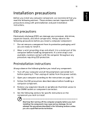
... for specific instructions on page 10. 3 Follow the ESD precautions described above before handling a computer component. 4 Remove any procedure requiring ESD protection. Not turning off your computer and all cables from the power outlets. 2 Open your processor, disk drives, expansion boards, and other components. Preinstallation instructions Always observe the following sections unless you are ready to the DIMM sockets or component connectors. 5 See...
... for specific instructions on page 10. 3 Follow the ESD precautions described above before handling a computer component. 4 Remove any procedure requiring ESD protection. Not turning off your computer and all cables from the power outlets. 2 Open your processor, disk drives, expansion boards, and other components. Preinstallation instructions Always observe the following sections unless you are ready to the DIMM sockets or component connectors. 5 See...

Veriton M661/T661/S661 Series User's Guide - EN
Page 22
.... Replacing the hard disk Follow these steps to replace your computer Your computer automatically detects the amount of it with the socket (a). English Note: The DDR2 DIMM sockets are slotted to the new hard disk. To reconfigure your computer's hard disk: 1 Remove the computer cover. 2 Detach all cables to ensure proper installation. Run the BIOS utility to view the new value for total system memory and make a note of memory installed. Set the drive...
.... Replacing the hard disk Follow these steps to replace your computer Your computer automatically detects the amount of it with the socket (a). English Note: The DDR2 DIMM sockets are slotted to the new hard disk. To reconfigure your computer's hard disk: 1 Remove the computer cover. 2 Detach all cables to ensure proper installation. Run the BIOS utility to view the new value for total system memory and make a note of memory installed. Set the drive...
Veriton M661/T661/S661 Series User's Guide - EN
Page 23
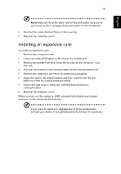
... the newly installed devices. Installing an expansion card To install an expansion card: 1 Remove the computer cover. 2 Locate an empty PCI Express or PCI slot on the computer, BIOS automatically detects and assigns resources to the computer. Make sure that the card is properly seated. 7 Secure the card to your computer with the bracket lock you want to replace or upgrade any of the disk cables are securely connected to the...
... the newly installed devices. Installing an expansion card To install an expansion card: 1 Remove the computer cover. 2 Locate an empty PCI Express or PCI slot on the computer, BIOS automatically detects and assigns resources to the computer. Make sure that the card is properly seated. 7 Secure the card to your computer with the bracket lock you want to replace or upgrade any of the disk cables are securely connected to the...
Veriton M661/T661/S661 Series User's Guide - EN
Page 26
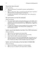
... disk. • Make sure the CD or DVD is inserted into the drive correctly. • Check if the CD or DVD is not write-protected. • Make sure you are using a good (undamaged) disk. If it is turned on. • Make sure the printer cable is crossed-out, click on . • If headphones, earphones or external speakers are connected to the system's parallel or USB port...
... disk. • Make sure the CD or DVD is inserted into the drive correctly. • Check if the CD or DVD is not write-protected. • Make sure you are using a good (undamaged) disk. If it is turned on. • Make sure the printer cable is crossed-out, click on . • If headphones, earphones or external speakers are connected to the system's parallel or USB port...
Veriton M661/T661/S661 Series User's Guide - EN
Page 31
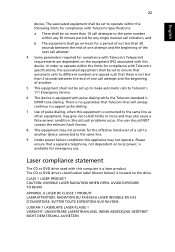
... to operate within the limits for compliance with Telecom's specifications, the associated equipment shall be set up to make automatic calls to support pulse dialing. 7 Use of the next call attempt. 4 Some parameters required for compliance with this equipment is a laser product. AVOID EXPOSURE TO BEAM. The CD or DVD drive's classification label (shown below) is located on the...
... to operate within the limits for compliance with Telecom's specifications, the associated equipment shall be set up to make automatic calls to support pulse dialing. 7 Use of the next call attempt. 4 Some parameters required for compliance with this equipment is a laser product. AVOID EXPOSURE TO BEAM. The CD or DVD drive's classification label (shown below) is located on the...


