Veriton 3200 Service Guide
Page 6
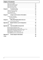
Table of Contents Removing the DIMM 57 Removing the Power Supply 57 Removing the RTC Battery 58 Removing the Processor 58 Removing the Main board 59 Chapter 4 Troubleshooting 60 Power-On Self-Test (POST 61 POST Error Messages List 62 Error Symptoms List 64 Undetermined ...Problems 68 Chapter 5 Jumper and Connector Information 70 Jumpers and Connectors 70 Connector Description 71 Jumper Setting 72 Chapter 6 FRU (Field Replaceable Unit) List 74 Veriton 3200 Exploded ...
Table of Contents Removing the DIMM 57 Removing the Power Supply 57 Removing the RTC Battery 58 Removing the Processor 58 Removing the Main board 59 Chapter 4 Troubleshooting 60 Power-On Self-Test (POST 61 POST Error Messages List 62 Error Symptoms List 64 Undetermined ...Problems 68 Chapter 5 Jumper and Connector Information 70 Jumpers and Connectors 70 Connector Description 71 Jumper Setting 72 Chapter 6 FRU (Field Replaceable Unit) List 74 Veriton 3200 Exploded ...
Veriton 3200 Service Guide
Page 11
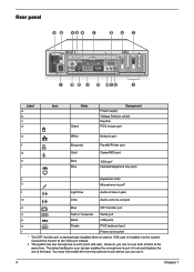
... automatically disabled when an add-on VGA card is installed into the system. Rear panel Label a b c d e f g h i Icon Color Green White Burgundy Gold Blue Blue Component Power supply Voltage Selector switch Keyhole PS/2 mouse port Network port Parallel/Printer port Game/MIDI port VGA port* Handset/telephone line ports j Expansion slots k Microphone-in...
... automatically disabled when an add-on VGA card is installed into the system. Rear panel Label a b c d e f g h i Icon Color Green White Burgundy Gold Blue Blue Component Power supply Voltage Selector switch Keyhole PS/2 mouse port Network port Parallel/Printer port Game/MIDI port VGA port* Handset/telephone line ports j Expansion slots k Microphone-in...
Veriton 3200 Service Guide
Page 24
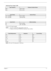
... input 90VRMS and maximum load condition. Output Requirements +5V +12V -12V +3.3V -5V +5Vaux +-5% +-5% +-10% +-5% +-10% +-5% Regulation NOTE: +5V and 3.3V total power is for 145 power supply) NOTE: 1. Switching Power Supply 145W 50Hz 60Hz Input Frequency 47Hz to 53Hz 57Hz to 63Hz Frequency Variation Range Input Voltage 100 - 120 VRMS 200 - 240 VRMS 90...
... input 90VRMS and maximum load condition. Output Requirements +5V +12V -12V +3.3V -5V +5Vaux +-5% +-5% +-10% +-5% +-10% +-5% Regulation NOTE: +5V and 3.3V total power is for 145 power supply) NOTE: 1. Switching Power Supply 145W 50Hz 60Hz Input Frequency 47Hz to 53Hz 57Hz to 63Hz Frequency Variation Range Input Voltage 100 - 120 VRMS 200 - 240 VRMS 90...
Veriton 3200 Service Guide
Page 57
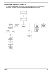
Disassembly Procedure Flowchart The flowchart on the succeeding page gives you a graphical representation on the entire disassembly sequence and instructs you on the components that need to be removed during servicing. Main Unit Upper Case FDD & DVD Bracket Power Supply DVDROM FDD DIMM CPU Fan HDD Bracket CPU HDD Main board Front Panel Audio & USB Board Modem Card Chapter 3 50
Disassembly Procedure Flowchart The flowchart on the succeeding page gives you a graphical representation on the entire disassembly sequence and instructs you on the components that need to be removed during servicing. Main Unit Upper Case FDD & DVD Bracket Power Supply DVDROM FDD DIMM CPU Fan HDD Bracket CPU HDD Main board Front Panel Audio & USB Board Modem Card Chapter 3 50
Veriton 3200 Service Guide
Page 64
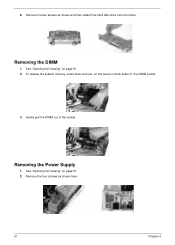
To release the system memory, press down and out on the levers on page 51 2. See "Opening the Housing" on both sides of the socket. Removing the Power Supply 1. Remove the two screws as shown here. 57 Chapter 3 6. See "Opening the Housing" on page 51 2. Remove the four screws as shown and then detach the hard disk drive from the frame. Gently pull the DIMM out of the DIMM socket. 3. Removing the DIMM 1.
To release the system memory, press down and out on the levers on page 51 2. See "Opening the Housing" on both sides of the socket. Removing the Power Supply 1. Remove the two screws as shown here. 57 Chapter 3 6. See "Opening the Housing" on page 51 2. Remove the four screws as shown and then detach the hard disk drive from the frame. Gently pull the DIMM out of the DIMM socket. 3. Removing the DIMM 1.
Veriton 3200 Service Guide
Page 65
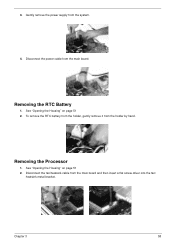
Gently remove the power supply from the holder by hand. Removing the RTC Battery 1. See "Opening the Housing" on page 51 2. To remove the RTC battery from the holder, gently remove it from the system. 4. Disconnect the fan/heatsink cable from the main board. Removing the Processor 1. Chapter 3 58 See "Opening the Housing" on page 51 2. Disconnect the power cable from the main board and then insert a flat screw driver into the fan/ heatsink metal bracket. 3.
Gently remove the power supply from the holder by hand. Removing the RTC Battery 1. See "Opening the Housing" on page 51 2. To remove the RTC battery from the holder, gently remove it from the system. 4. Disconnect the fan/heatsink cable from the main board. Removing the Processor 1. Chapter 3 58 See "Opening the Housing" on page 51 2. Disconnect the power cable from the main board and then insert a flat screw driver into the fan/ heatsink metal bracket. 3.
Veriton 3200 Service Guide
Page 69
...Main board 1. RTC Battery. 3. Ensure the system configuration set in right column is correct. 2. Main board. 1. Main board 1. Remove all power supply voltages, switch, and jumper settings before you replace the main board. Load default settings in the check procedure. If directed to a check procedure... settings. 2. Enter BIOS Setup and load the default settings. 2. Remove all adapter cards that no -power" condition. Ensure that are NOT factory- Also check the power supply voltages if you have done so, you must run the diagnostics program tests but did receive a POST...
...Main board 1. RTC Battery. 3. Ensure the system configuration set in right column is correct. 2. Main board. 1. Main board 1. Remove all power supply voltages, switch, and jumper settings before you replace the main board. Load default settings in the check procedure. If directed to a check procedure... settings. 2. Enter BIOS Setup and load the default settings. 2. Remove all adapter cards that no -power" condition. Ensure that are NOT factory- Also check the power supply voltages if you have done so, you must run the diagnostics program tests but did receive a POST...
Veriton 3200 Service Guide
Page 71
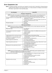
...Index of processor fan connector. Diskette/IDE drive connection/cables 2. Diskette drive 5. Diskette drive 5. System works but power supply fan runs. 1. Diskette drive power 3. Diskette/IDE disk drives 3. Main board Diskette Drive NOTE: Ensure the diskette drive is configured correctly in BIOS... Execute a system test and set to see the potential cause of BIOS Setup. 2. Diskette drive connection/cable 4. See "Power Management" in the left column. Error Symptom Action/FRU Processor / Processor Fan NOTE: Normally, the processor fan should be ...
...Index of processor fan connector. Diskette/IDE drive connection/cables 2. Diskette drive 5. Diskette drive 5. System works but power supply fan runs. 1. Diskette drive power 3. Diskette/IDE disk drives 3. Main board Diskette Drive NOTE: Ensure the diskette drive is configured correctly in BIOS... Execute a system test and set to see the potential cause of BIOS Setup. 2. Diskette drive connection/cable 4. See "Power Management" in the left column. Error Symptom Action/FRU Processor / Processor Fan NOTE: Normally, the processor fan should be ...
Veriton 3200 Service Guide
Page 74
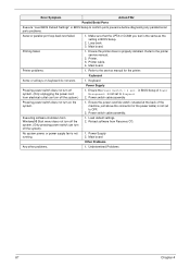
... problems. 1. Keyboard Some or all keys on the system. 1. Keyboard Power Supply Pressing power switch does not turn off the system). 1. Load default settings. 2. No system power, or power supply fan is properly installed. Ensure the printer driver is not running. 1. Printer cable. 4. Power Supply 2. Loop-back. 3. Printer. 3. Power switch cable assembly. Reload software from electrical outlet can turn...
... problems. 1. Keyboard Some or all keys on the system. 1. Keyboard Power Supply Pressing power switch does not turn off the system). 1. Load default settings. 2. No system power, or power supply fan is properly installed. Ensure the printer driver is not running. 1. Printer cable. 4. Power Supply 2. Loop-back. 3. Printer. 3. Power switch cable assembly. Reload software from electrical outlet can turn...
Veriton 3200 Service Guide
Page 75
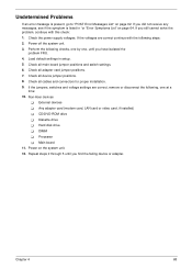
... disconnect the following steps: 2. Power off the system unit. 3. Non-Acer devices ! CD/DVD-ROM drive ! Perform the following checks, one by one at a time: 10. Hard disk drive ! DIMM ! Chapter 4 68 Main board 11. Power on the system unit. 12. Check all device jumper positions. 8. Processor ! Check the power supply voltages. Load default settings...
... disconnect the following steps: 2. Power off the system unit. 3. Non-Acer devices ! CD/DVD-ROM drive ! Perform the following checks, one by one at a time: 10. Hard disk drive ! DIMM ! Chapter 4 68 Main board 11. Power on the system unit. 12. Check all device jumper positions. 8. Processor ! Check the power supply voltages. Load default settings...
Veriton 3200 Service Guide
Page 86
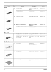
SPS 145W FSP/PFC FSP- 56.04145.GA1 145-60SA 145-60SA POWER SUPPLY 145W PFC SPI/ SPS 145W PFC SPI/FSP145- 56.04145.GC1 FSP145-60SA 60SA Case/Cover/Bracket assembly 1-5 I/O BRACKET ASSEMBLY IO BRACKET(S58M)H34 60.... MODEM BOARD 56K AMBIT MODEM BOARD 56K ASKEY MODEM 56K 90 AMBIT/ T62M154.04 MODEM 56K ASKEY/ 1456VQH20E-004 54.09011.461 54.09262.121 Power Supply 2 POWER SUPPLY 145W FSP/FSP-
SPS 145W FSP/PFC FSP- 56.04145.GA1 145-60SA 145-60SA POWER SUPPLY 145W PFC SPI/ SPS 145W PFC SPI/FSP145- 56.04145.GC1 FSP145-60SA 60SA Case/Cover/Bracket assembly 1-5 I/O BRACKET ASSEMBLY IO BRACKET(S58M)H34 60.... MODEM BOARD 56K AMBIT MODEM BOARD 56K ASKEY MODEM 56K 90 AMBIT/ T62M154.04 MODEM 56K ASKEY/ 1456VQH20E-004 54.09011.461 54.09262.121 Power Supply 2 POWER SUPPLY 145W FSP/FSP-
Veriton 3200 Service Guide
Page 105
... 37 Setup password 37 Serial Port 13 socket memory 9 Socket 370 9 Suspend Mode 18 Switching Power Supply 102W 17 Symptoms List 64 Audio 66 CD/DVD-ROM Drive 65 Diskette Drive 64 Keyboard 67 ...Memory 64 Modem 66 Monitor 66 Other 67 Parallel Port 67 Power Supply 67 Processor / Processor Fan 64 Real-Time Clock 66 Serial Port 67 System Board 64 Video... Setup 47 Load Default Settings 45 Memory/Cache Options 40 Onboard Peripherals 30 PnP/PCI Options 42 Power Management 32 Product Information 25 System Security 37 Time 36 T Temperature 16 Test Compatible Components 86 ...
... 37 Setup password 37 Serial Port 13 socket memory 9 Socket 370 9 Suspend Mode 18 Switching Power Supply 102W 17 Symptoms List 64 Audio 66 CD/DVD-ROM Drive 65 Diskette Drive 64 Keyboard 67 ...Memory 64 Modem 66 Monitor 66 Other 67 Parallel Port 67 Power Supply 67 Processor / Processor Fan 64 Real-Time Clock 66 Serial Port 67 System Board 64 Video... Setup 47 Load Default Settings 45 Memory/Cache Options 40 Onboard Peripherals 30 PnP/PCI Options 42 Power Management 32 Product Information 25 System Security 37 Time 36 T Temperature 16 Test Compatible Components 86 ...
Veriton 3200 User Guide
Page 6
... rating. It should be a detachable type: UL listed/CSA certified, type SPT-2, rated 7A 125V minimum, VDE approved or its equivalent. Never push objects of power supply cord set (provided in your accessories box) for service. 12. Never spill liquid of fire or explosion. When the... power cord or plug is 15 feet (4.6 meters). Adjust only those controls that could result in damage and will often require extensive work by a qualified technician ...
... rating. It should be a detachable type: UL listed/CSA certified, type SPT-2, rated 7A 125V minimum, VDE approved or its equivalent. Never push objects of power supply cord set (provided in your accessories box) for service. 12. Never spill liquid of fire or explosion. When the... power cord or plug is 15 feet (4.6 meters). Adjust only those controls that could result in damage and will often require extensive work by a qualified technician ...
Veriton 3200 User Guide
Page 23
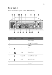
13 Rear panel Your computer's rear panel consists of the following: Label a b c d Icon e f g h Color Green Component Power supply Voltage Selector switch Keyhole PS/2 mouse port Gray Network port Burgundy Parallel/Printer port Gold Game/MIDI port VGA porta
13 Rear panel Your computer's rear panel consists of the following: Label a b c d Icon e f g h Color Green Component Power supply Voltage Selector switch Keyhole PS/2 mouse port Gray Network port Burgundy Parallel/Printer port Gold Game/MIDI port VGA porta
Veriton 3200 User Guide
Page 61
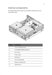
51 Internal components The figure below shows what your computer looks like once you remove the cover: Number Component 1 3.5-inch floppy disk drive 2 CD-ROM/DVD-ROM/CD-RW drive 3 Drive frame 4 Power supply 5 Mainboard 6 VGA card (optional) 7 Modem card (optional) 8 Expansion slot
51 Internal components The figure below shows what your computer looks like once you remove the cover: Number Component 1 3.5-inch floppy disk drive 2 CD-ROM/DVD-ROM/CD-RW drive 3 Drive frame 4 Power supply 5 Mainboard 6 VGA card (optional) 7 Modem card (optional) 8 Expansion slot


