
TravelMate 3000 Service Guide
Page 6
...BIOS Setup Utility 32 BIOS Flash Utility 44 Chapter 3 Machine Disassembly and Replacement 45 General Information 46 Disassembly Procedure Flowchart 47 Removing the Battery Pack 49 Removing the miniPCI/Memory/HDD Module/Keyboard . . . 50 Seperate the LCD module and main unit 52 Disassemble the ...78 Chapter 6 FRU (Field Replaceable Unit) List 79 Exploded Diagram 80 FRU List 84 Appendix A Model Definition and Configuration 90 TravelMate 3000 Series 90 Appendix B Test Compatible Components 91 Microsoft® Windows® XP Pro Environment Test 92 Appendix C Online Support Information 94 Chapter ...
...BIOS Setup Utility 32 BIOS Flash Utility 44 Chapter 3 Machine Disassembly and Replacement 45 General Information 46 Disassembly Procedure Flowchart 47 Removing the Battery Pack 49 Removing the miniPCI/Memory/HDD Module/Keyboard . . . 50 Seperate the LCD module and main unit 52 Disassemble the ...78 Chapter 6 FRU (Field Replaceable Unit) List 79 Exploded Diagram 80 FRU List 84 Appendix A Model Definition and Configuration 90 TravelMate 3000 Series 90 Appendix B Test Compatible Components 91 Microsoft® Windows® XP Pro Environment Test 92 Appendix C Online Support Information 94 Chapter ...
TravelMate 3000 Service Guide
Page 14
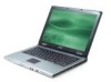
... Lights when the battery is on models with infrared devices(e.g. infrared printer and IR-aware computer) NOTE: The Bluetooth and Wireless buttons and indicators only work on . Loghts to ...
... Lights when the battery is on models with infrared devices(e.g. infrared printer and IR-aware computer) NOTE: The Bluetooth and Wireless buttons and indicators only work on . Loghts to ...
TravelMate 3000 Service Guide
Page 17
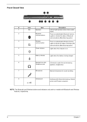
Rear Panel # # Item 1 2 3 Icon Item DePscorwipetriojanck Description Connectos to an AC adaptor N/A Battery Nay Houses the computer's battery pack 124-pin Acer ezDock Connects to Acer ezDock connector Chapter 1 11
Rear Panel # # Item 1 2 3 Icon Item DePscorwipetriojanck Description Connectos to an AC adaptor N/A Battery Nay Houses the computer's battery pack 124-pin Acer ezDock Connects to Acer ezDock connector Chapter 1 11
TravelMate 3000 Service Guide
Page 18
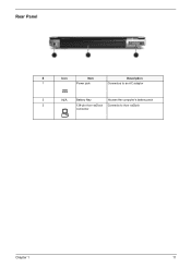
Houses the computer's main memory Unlatches the battery to stay cool. Note: Do not cover or obstruct the opening of the fan. Helps keep th ecomputer cool. Enable the computer to remove the battery pack. 12 Chapter 1 Bottom Panel # Item # 1 2 3 4 5 6 Icon N/A N/A N/A N/A N/A N/A Description Item Battery bay Battery lock latches cooling fan Note Ventilation slots Memory compartment Battery release latch Description Houses the computer's battery pack Lock the battery in place.
Houses the computer's main memory Unlatches the battery to stay cool. Note: Do not cover or obstruct the opening of the fan. Helps keep th ecomputer cool. Enable the computer to remove the battery pack. 12 Chapter 1 Bottom Panel # Item # 1 2 3 4 5 6 Icon N/A N/A N/A N/A N/A N/A Description Item Battery bay Battery lock latches cooling fan Note Ventilation slots Memory compartment Battery release latch Description Houses the computer's battery pack Lock the battery in place.
TravelMate 3000 Service Guide
Page 19
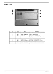
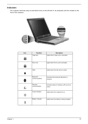
Indicates status of the computer. Indicators The computer has three easy-to-read status icons on the left side of the keyboard, and four located on . Num lock Lights when Num Lock is enabled. HDD Lights when the disc drive is active Bluetooth communications Wireless communication Power indicator Indicates that (optional) Bluetooth is activated. Lights when the computer is activated. Icon Function Caps lock Description Lights when Caps Lock is on the front of wireless LAN communication. Battery indicator Lights when the battery is being charged Chapter 1 13
Indicates status of the computer. Indicators The computer has three easy-to-read status icons on the left side of the keyboard, and four located on . Num lock Lights when Num Lock is enabled. HDD Lights when the disc drive is active Bluetooth communications Wireless communication Power indicator Indicates that (optional) Bluetooth is activated. Lights when the computer is activated. Icon Function Caps lock Description Lights when Caps Lock is on the front of wireless LAN communication. Battery indicator Lights when the battery is being charged Chapter 1 13

TravelMate 3000 Service Guide
Page 35
...number of keypads Windows logo key and Application key Multi-Language Specification NS87541 Standard keyboard N/A Yes Yes Battery Item Vendor & model name Battery Type Typical capacity Cell voltage Number of battery cell Package configuration Pin 1 Pin 2 Pin 3 Pin 4 Pin 5 Panasonic Li-ion 4700mAh 3700... mV 6 GND SDA SCL TH BAT+ Specification Item Vendor & model name Battery Type Typical capacity Cell voltage Number of battery cell Package configuration Pin 1 Sanyo...
...number of keypads Windows logo key and Application key Multi-Language Specification NS87541 Standard keyboard N/A Yes Yes Battery Item Vendor & model name Battery Type Typical capacity Cell voltage Number of battery cell Package configuration Pin 1 Pin 2 Pin 3 Pin 4 Pin 5 Panasonic Li-ion 4700mAh 3700... mV 6 GND SDA SCL TH BAT+ Specification Item Vendor & model name Battery Type Typical capacity Cell voltage Number of battery cell Package configuration Pin 1 Sanyo...
TravelMate 3000 Service Guide
Page 50
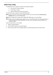
..., you use the Phlash. Copy the Phlash utilities to update the system BIOS flash ROM. Use the Phlash utility to the bootable diskette. 3. If the battery pack does not contain enough power to run the Phlash utility. NOTE: If you do not have a crisis recovery diskette at hand, then you should...
..., you use the Phlash. Copy the Phlash utilities to update the system BIOS flash ROM. Use the Phlash utility to the bootable diskette. 3. If the battery pack does not contain enough power to run the Phlash utility. NOTE: If you do not have a crisis recovery diskette at hand, then you should...

TravelMate 3000 Service Guide
Page 52
Remove the battery pack. Please refer the picture below, group the same type of screws used to tear the tape or mylar before you may be too long ... to secure bottom case and upper case assembly. The screws vary in length. Turn off the power to damage the main board. 46 Chapter 3 NOTE: TravelMate 3000 series product uses mylar or tape to fasten the FFC/FPC/connectors/cable, you disconnect different FFC/FPC/connectors. NOTE: There are several types of...
Remove the battery pack. Please refer the picture below, group the same type of screws used to tear the tape or mylar before you may be too long ... to secure bottom case and upper case assembly. The screws vary in length. Turn off the power to damage the main board. 46 Chapter 3 NOTE: TravelMate 3000 series product uses mylar or tape to fasten the FFC/FPC/connectors/cable, you disconnect different FFC/FPC/connectors. NOTE: There are several types of...

TravelMate 3000 Service Guide
Page 54
Remove the battery pack. 48 Chapter 3 Removing the Battery Pack 1. Slide the battery latch. 3. Release the battery lock. 2.
Remove the battery pack. 48 Chapter 3 Removing the Battery Pack 1. Slide the battery latch. 3. Release the battery lock. 2.
TravelMate 3000 Service Guide
Page 66
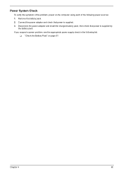
then check that power is supplied by the battery pack. If you suspect a power problem, see the appropriate power supply check in the following list: T "Check the Battery Pack" on the computer using each of the following power sources: 1. Remove the battery pack. 2. Connect the power adapter and check that power is supplied. 3. Disconnect the power adapter and install the charged battery pack; Power System Check To verify the symptom of the problem, power on page 61 Chapter 4 60
then check that power is supplied by the battery pack. If you suspect a power problem, see the appropriate power supply check in the following list: T "Check the Battery Pack" on the computer using each of the following power sources: 1. Remove the battery pack. 2. Connect the power adapter and check that power is supplied. 3. Disconnect the power adapter and install the charged battery pack; Power System Check To verify the symptom of the problem, power on page 61 Chapter 4 60
TravelMate 3000 Service Guide
Page 67
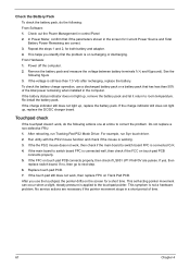
...necessary if the pointer movement stops in a short period of the total power remaining when installed in the computer. Remove the battery pack and measure the voltage between battery terminals 1(+) and 6(ground). If the voltage is still less than 50% of time. 61 Chapter 4 If the charge indicator... still does not light up, replace the battery pack. If yes, then replace switch board. After you identify first the problem is working. 3. In Power Meter, confirm that has less than 7.5...
...necessary if the pointer movement stops in a short period of the total power remaining when installed in the computer. Remove the battery pack and measure the voltage between battery terminals 1(+) and 6(ground). If the voltage is still less than 50% of time. 61 Chapter 4 If the charge indicator... still does not light up, replace the battery pack. If yes, then replace switch board. After you identify first the problem is working. 3. In Power Meter, confirm that has less than 7.5...
TravelMate 3000 Service Guide
Page 69
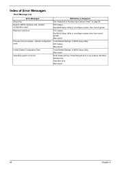
... configuration used Invalid System Configuration Data Operating system not found FRU/Action in Sequence See "Keyboard or Auxiliary Input Device Check" on page 59 RTC battery Run BIOS Setup Utility to reconfigure system time, then reboot system. Index of Error Messages Error Message List Error Messages Struck Key System CMOS checksum... bad - Main board Enter Setup and see if fixed disk and drive A are properly identified. RTC battery Run BIOS Setup Utility to reconfigure system, then reboot system. RTC...
... configuration used Invalid System Configuration Data Operating system not found FRU/Action in Sequence See "Keyboard or Auxiliary Input Device Check" on page 59 RTC battery Run BIOS Setup Utility to reconfigure system time, then reboot system. Index of Error Messages Error Message List Error Messages Struck Key System CMOS checksum... bad - Main board Enter Setup and see if fixed disk and drive A are properly identified. RTC battery Run BIOS Setup Utility to reconfigure system, then reboot system. RTC...
TravelMate 3000 Service Guide
Page 70
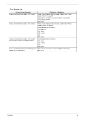
Reconnect the DIMM. Main board. Power source (battery pack and power adapter.) See "Power System Check" on page 60 Reconnect the LCD connector Hard disk drive LCD cable LCD inverter LCD Main board ... inverter LCD Main board Power-on indicator turns on page 60 Ensure every connector is connected tightly and correctly. Reconnect the LCD connectors. Power source (battery pack and power adapter.) See "Power System Check" on and a blinking cursor Ensure every connector is connected tightly and correctly. Main board Chapter 4 64 Error...
Reconnect the DIMM. Main board. Power source (battery pack and power adapter.) See "Power System Check" on page 60 Reconnect the LCD connector Hard disk drive LCD cable LCD inverter LCD Main board ... inverter LCD Main board Power-on indicator turns on page 60 Ensure every connector is connected tightly and correctly. Reconnect the LCD connectors. Power source (battery pack and power adapter.) See "Power System Check" on and a blinking cursor Ensure every connector is connected tightly and correctly. Main board Chapter 4 64 Error...

TravelMate 3000 Service Guide
Page 75
... Settings" then reboot the system. Reconnect the LCD connectors. Action in the HDD. See "Power System Check" on . Reconnect the LCD connectors. Battery pack Power adapter CPU Main board In Windows XP operating system, hold and press the power switch for more than 4 seconds. If the system can...Wrong color displayed LCD has extra horizontal or vertical lines displayed. See "Power System Check" on page 60. Verify OS in Sequence Power source (battery pack and power adapter). Main board 69 Chapter 4 The system cannot power-off , then the main board is overheat (Heat sink or fan)....
... Settings" then reboot the system. Reconnect the LCD connectors. Action in the HDD. See "Power System Check" on . Reconnect the LCD connectors. Battery pack Power adapter CPU Main board In Windows XP operating system, hold and press the power switch for more than 4 seconds. If the system can...Wrong color displayed LCD has extra horizontal or vertical lines displayed. See "Power System Check" on page 60. Verify OS in Sequence Power source (battery pack and power adapter). Main board 69 Chapter 4 The system cannot power-off , then the main board is overheat (Heat sink or fan)....
TravelMate 3000 Service Guide
Page 76
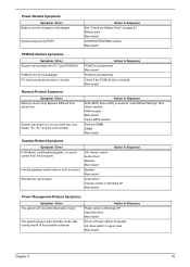
...Memory count (size) appears different from the computer. PC Card cannot be charged or discharged System hang during POST Action in Sequence See "Check the Battery Pack" on , but you hear two long beeps: "B--, B--" and the LCD is blank. Action in Sequence Power option in Windows XP Hard...if the PCMCIA slot is damaged. Internal speakers make noise or emit no sound comes from actual size. Power-Related Symptoms Symptom / Error Battery can power on page 61. Microphone cannot work Action in Sequence OS volume control Audio driver Speaker Main board Speaker Main board Audio driver...
...Memory count (size) appears different from the computer. PC Card cannot be charged or discharged System hang during POST Action in Sequence See "Check the Battery Pack" on , but you hear two long beeps: "B--, B--" and the LCD is blank. Action in Sequence Power option in Windows XP Hard...if the PCMCIA slot is damaged. Internal speakers make noise or emit no sound comes from actual size. Power-Related Symptoms Symptom / Error Battery can power on page 61. Microphone cannot work Action in Sequence OS volume control Audio driver Speaker Main board Speaker Main board Audio driver...

TravelMate 3000 Service Guide
Page 77
... not work correctly. Hard disk drive Main board The system doesn't resume from hibernation/ standby mode. Refresh battery (continue use battery until power off, then charge battery). Main board Peripheral-Related Symptoms Symptom / Error System configuration does not match the installed devices. Action in ...board Main board Enter BIOS Setup Utility to execute "Load Default Settings" then reboot the system. Run printer self-test. Battery pack Main board System hangs intermittently. Touchpad does not work correctly Print problems. Parallel port device problems Action in Sequence ...
... not work correctly. Hard disk drive Main board The system doesn't resume from hibernation/ standby mode. Refresh battery (continue use battery until power off, then charge battery). Main board Peripheral-Related Symptoms Symptom / Error System configuration does not match the installed devices. Action in ...board Main board Enter BIOS Setup Utility to execute "Load Default Settings" then reboot the system. Run printer self-test. Battery pack Main board System hangs intermittently. Touchpad does not work correctly Print problems. Parallel port device problems Action in Sequence ...
TravelMate 3000 Service Guide
Page 80
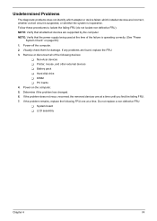
Power-off the computer. 2. If the problem remains, replace the following devices: T Non-Acer devices T Printer, mouse, and other external devices T Battery pack T Hard disk drive T DIMM T PC Cards 4. Visually check them for damage. Determine if the problem has changed. 6. Do not replace a non-defective FRU: T System ...
Power-off the computer. 2. If the problem remains, replace the following devices: T Non-Acer devices T Printer, mouse, and other external devices T Battery pack T Hard disk drive T DIMM T PC Cards 4. Visually check them for damage. Determine if the problem has changed. 6. Do not replace a non-defective FRU: T System ...
TravelMate 3000 Service Guide
Page 84
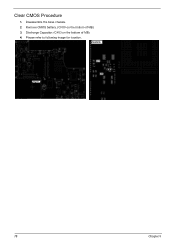
Disassemble the base chassis. 2. Please refer to following image for location. 78 Chapter 5 Remove CMOS battery. (CN19 on the bottom of MB) 3. Discharge Capacitor. (C403 on the bottom of MB) 4. Clear CMOS Procedure 1.
Disassemble the base chassis. 2. Please refer to following image for location. 78 Chapter 5 Remove CMOS battery. (CN19 on the bottom of MB) 3. Discharge Capacitor. (C403 on the bottom of MB) 4. Clear CMOS Procedure 1.
TravelMate 3000 Service Guide
Page 87
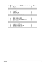
Item List Item 8 9 10 11 12 13 14 15 16 17 18 19 20 21 22 23 24 25 Description MB assy DC/B assy Audio/B assy SW/B assy TP/B assy Hinge Cover-L assy Hinge Cover_R assy HDD IC25N060ATMR04-0 STN B/S K/B module(UI) Battery module(6 cell 3S2P) Battery module(3 cell 3S1P) Bluetooth module MTN1-USB 91.BU513.002 Modem 56K(MDC) Screw M2.5*6.0-I(NI)(NYLOK) Screw M2.0*4.0-I(NI)(NYLOK) Screw M2.0*7.0-I(NI)(NYLOK) Screw M2.0*5-I(NI)(NYLIK)D4 T0.8 Screw M3.0*3.8(I)-NIH-J(4.6,0.3) Q'ty 1 1 1 1 1 1 1 1 1 1 1 1 1 4 5 18 11 4 Chapter 6 81
Item List Item 8 9 10 11 12 13 14 15 16 17 18 19 20 21 22 23 24 25 Description MB assy DC/B assy Audio/B assy SW/B assy TP/B assy Hinge Cover-L assy Hinge Cover_R assy HDD IC25N060ATMR04-0 STN B/S K/B module(UI) Battery module(6 cell 3S2P) Battery module(3 cell 3S1P) Bluetooth module MTN1-USB 91.BU513.002 Modem 56K(MDC) Screw M2.5*6.0-I(NI)(NYLOK) Screw M2.0*4.0-I(NI)(NYLOK) Screw M2.0*7.0-I(NI)(NYLOK) Screw M2.0*5-I(NI)(NYLIK)D4 T0.8 Screw M3.0*3.8(I)-NIH-J(4.6,0.3) Q'ty 1 1 1 1 1 1 1 1 1 1 1 1 1 4 5 18 11 4 Chapter 6 81

TravelMate 3000 Service Guide
Page 90
... List TravelMate 3000 FRU List Picture No. Adapter Battery Partname And Description Part Number ADAPTER 65W 3 PIN DELTA SADP-65KB BF ADAPTER 65W 3 PIN LITE-ON PA-1650-02 QA 19V AP.06501.005 AP.06503.006 BATTERY SANYO LI-ION 3S2P 6CELL 4800mAH BT.00603.003 Boards BATTERY PANASONIC LI-ION 3S2P 6CELL 4800mAH BATTERY...
... List TravelMate 3000 FRU List Picture No. Adapter Battery Partname And Description Part Number ADAPTER 65W 3 PIN DELTA SADP-65KB BF ADAPTER 65W 3 PIN LITE-ON PA-1650-02 QA 19V AP.06501.005 AP.06503.006 BATTERY SANYO LI-ION 3S2P 6CELL 4800mAH BT.00603.003 Boards BATTERY PANASONIC LI-ION 3S2P 6CELL 4800mAH BATTERY...


