
User Manual
Page 11
... AC Power cord 3 Power saving 3 Display Data Channel (DDC) 4 Connector pin assignment 4 15-pin color display signal cable 4 24-pin color display signal cable 5 Standard timing table 6 Installation 7 Users controls 8 Panel controls 8 Using the Shortcut Menu 9 Acer eColor Management 9 Operation instructions 9 Features and benefits 10 Using the OSD Menus 10 Picture Menu 11...
... AC Power cord 3 Power saving 3 Display Data Channel (DDC) 4 Connector pin assignment 4 15-pin color display signal cable 4 24-pin color display signal cable 5 Standard timing table 6 Installation 7 Users controls 8 Panel controls 8 Using the Shortcut Menu 9 Acer eColor Management 9 Operation instructions 9 Features and benefits 10 Using the OSD Menus 10 Picture Menu 11...
User Manual
Page 15
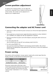
...V. • For units using both of your area. • The monitor has a universal power supply that the power cord you can be kept until a control signal has been detected or the keyboard or mouse is required. • Plug one end of the monitor. The recovery time from the display controller, as... indicated by the control signal from "power saving" mode back to "on" is the correct type required for the country in which the equipment will be switched to hold the...
...V. • For units using both of your area. • The monitor has a universal power supply that the power cord you can be kept until a control signal has been detected or the keyboard or mouse is required. • Plug one end of the monitor. The recovery time from the display controller, as... indicated by the control signal from "power saving" mode back to "on" is the correct type required for the country in which the equipment will be switched to hold the...
User Manual
Page 16
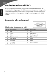
... 9 +5 V 10 Logic ground 11 Monitor ground 12 DDC-serial data 13 H-sync 14 V-sync 15 DDC-serial clock 4 Connector pin assignment 15-pin color display signal cable 1 5 6 10 11 15 PIN No. for example, supported resolutions and corresponding timing. The DDC is able to plug-and-play. Description 1 Red 2 Green 3 Blue...
... 9 +5 V 10 Logic ground 11 Monitor ground 12 DDC-serial data 13 H-sync 14 V-sync 15 DDC-serial clock 4 Connector pin assignment 15-pin color display signal cable 1 5 6 10 11 15 PIN No. for example, supported resolutions and corresponding timing. The DDC is able to plug-and-play. Description 1 Red 2 Green 3 Blue...
User Manual
Page 24
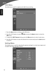
.... Setting Wide Mode DDC/CI ACM Input Language Reset Full ON OFF VGA English 12 OSD Menu The OSD menu is used for current input signal such as aspect ratio, OSD language, and etc. Setting Menu The Setting menu is used for adjusting the general settings for adjusting the OSD timeout...
.... Setting Wide Mode DDC/CI ACM Input Language Reset Full ON OFF VGA English 12 OSD Menu The OSD menu is used for current input signal such as aspect ratio, OSD language, and etc. Setting Menu The Setting menu is used for adjusting the general settings for adjusting the OSD timeout...
User Manual
Page 26
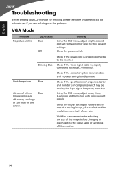
...or reset to their default settings. In case of monitor. Using the OSD menu, adjust focus, clock, H-position and V-position with non-standard signals. Check if the computer system is properly connected at the back of a missing image, please select another resolution or vertical refresh rate. Check if... cord is missing, off the monitor. 14 Check the power switch. Check if the specification of the image before changing or disconnecting the signal cable or switching off -center, too large or too small on your LCD monitor for a few seconds after adjusting the size of graphics...
...or reset to their default settings. In case of monitor. Using the OSD menu, adjust focus, clock, H-position and V-position with non-standard signals. Check if the computer system is properly connected at the back of a missing image, please select another resolution or vertical refresh rate. Check if... cord is missing, off the monitor. 14 Check the power switch. Check if the specification of the image before changing or disconnecting the signal cable or switching off -center, too large or too small on your LCD monitor for a few seconds after adjusting the size of graphics...
User Manual
Page 27
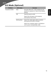
Check if the computer system is properly connected at the back of monitor. English DVI Mode (Optional) Problem No picture visible LED status Blue Off Remedy Using the OSD menu, adjust brightness and contrast to maximum or reset to the monitor. Blinking Blue Check if the video signal cable is switched on and in power saving/standby mode. 15 Check if the AC power cord is properly connected to their default settings. Check the power switch.
Check if the computer system is properly connected at the back of monitor. English DVI Mode (Optional) Problem No picture visible LED status Blue Off Remedy Using the OSD menu, adjust brightness and contrast to maximum or reset to the monitor. Blinking Blue Check if the video signal cable is switched on and in power saving/standby mode. 15 Check if the AC power cord is properly connected to their default settings. Check the power switch.


