

Power SC Service Guide
Page 13
Rear Panel The computer's rear panel consists of the following: Label 1 2 3 4 5 6 7 8 9 10 11 12 13 14 15 16 Description Fan PS/2 keyboard port USB ports Serial port VGA/Monitor port Speaker-out/Line-out port Line-in port Microphone-in port Add-on brackets System main power switch Voltage selector System power socket PS/2 mouse port LAN port Parallel port Game/MIDI port Chapter 1 5
Rear Panel The computer's rear panel consists of the following: Label 1 2 3 4 5 6 7 8 9 10 11 12 13 14 15 16 Description Fan PS/2 keyboard port USB ports Serial port VGA/Monitor port Speaker-out/Line-out port Line-in port Microphone-in port Add-on brackets System main power switch Voltage selector System power socket PS/2 mouse port LAN port Parallel port Game/MIDI port Chapter 1 5
Power SC Service Guide
Page 15
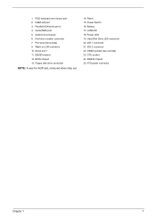
... chipset 25. PS/2 keyboard and mouse port 2. PCI slots (three slots) 9. Serial port 1 11. Battery 17. BIOS chipset 13. Hard Disk Drive LED connector 20. Power Switch 16. 1. USB/LAN port 3. Fax/voice modem connector 7. Audio/CD connector 6. Reset 15. DIMM sockets (two sockets) 23.
... chipset 25. PS/2 keyboard and mouse port 2. PCI slots (three slots) 9. Serial port 1 11. Battery 17. BIOS chipset 13. Hard Disk Drive LED connector 20. Power Switch 16. 1. USB/LAN port 3. Fax/voice modem connector 7. Audio/CD connector 6. Reset 15. DIMM sockets (two sockets) 23.

Power SC Service Guide
Page 28
Switching Power Supply 102W 50MHz 60MHz Input Frequency 47MHz to 53MHz 57MHz to 63MHz Frequency Variation Range Input Voltage 100 - 120 VRMS 200 - 240 VRMS 90 - 132 VRMS 180 - 264 VRMS Variation Range Input Current Measuring Range 4A 90 -132 VRMS 2A 180 - 264 VRMS NOTE: Measure at line input 90 VRMS and maximum load condition. Output Requirements +5V +12V -12V +3.3V +5Vaux +-5% +-5% +-10% +-4% +-5% Regulation NOTE: AcerPower Sc is using 145W power supply. 15A 3A 0.3A 12A 3A Current Rating 20 Chapter 1
Switching Power Supply 102W 50MHz 60MHz Input Frequency 47MHz to 53MHz 57MHz to 63MHz Frequency Variation Range Input Voltage 100 - 120 VRMS 200 - 240 VRMS 90 - 132 VRMS 180 - 264 VRMS Variation Range Input Current Measuring Range 4A 90 -132 VRMS 2A 180 - 264 VRMS NOTE: Measure at line input 90 VRMS and maximum load condition. Output Requirements +5V +12V -12V +3.3V +5Vaux +-5% +-5% +-10% +-4% +-5% Regulation NOTE: AcerPower Sc is using 145W power supply. 15A 3A 0.3A 12A 3A Current Rating 20 Chapter 1
Power SC Service Guide
Page 29
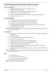
... in , keyboard and mouse for ACPI mode ACPI ! NOTE: AcerPower Sc : Resume method: Return to control the VESA DPMS monitor. ! ACPI specification 1.0. ! Power Management Function (ACPI support function) Device Standby Mode ! Independent power management timer (2-120 minutes, time step=10 minutes) or pushing external switch button. ! Resume recovery time: 3-5 sec. Disable H-sync and V-sync...
... in , keyboard and mouse for ACPI mode ACPI ! NOTE: AcerPower Sc : Resume method: Return to control the VESA DPMS monitor. ! ACPI specification 1.0. ! Power Management Function (ACPI support function) Device Standby Mode ! Independent power management timer (2-120 minutes, time step=10 minutes) or pushing external switch button. ! Resume recovery time: 3-5 sec. Disable H-sync and V-sync...
Power SC Service Guide
Page 44
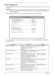
...IDE Hard Disk Standby Timer OFF] System Sleep Timer 30] Minute(s) Sleep Mode Suspend] Power Switch < 4 sec Power Off] System wake-up Event 36 Description Allows you to reduce the system's power consumption. Then the settings in this menu. Lets you specify the activity that the ... parameter is configurable only if the System Sleep Timer is non-effective. Parameter Power Management Mode IDE Hard Disk Standby Timer System Sleep Timer Sleep Mode Power Switch < 4 sec. Power Management The Power Management menu lets you specify whether to automatically turn off the machine or put...
...IDE Hard Disk Standby Timer OFF] System Sleep Timer 30] Minute(s) Sleep Mode Suspend] Power Switch < 4 sec Power Off] System wake-up Event 36 Description Allows you to reduce the system's power consumption. Then the settings in this menu. Lets you specify the activity that the ... parameter is configurable only if the System Sleep Timer is non-effective. Parameter Power Management Mode IDE Hard Disk Standby Timer System Sleep Timer Sleep Mode Power Switch < 4 sec. Power Management The Power Management menu lets you specify whether to automatically turn off the machine or put...
Power SC Service Guide
Page 76
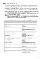
...PS/2 Keyboard Interface Error PS/2 Keyboard Locked Onboard xxx... Enter BIOS Setup and load the default settings. 2. System Board. 1. Also check the power supply voltages if you have done so, you are NOT factory- System board 1. RTC Battery. 3. Memory module. 3. Re-connect PS/2 .... 1. Enter BIOS Setup and load the default settings. 3. Remove all power supply voltages, switch, and jumper settings before you have deemed it necessary to replace an FRU, and have a "system no-power" condition. This system check can be done through the diagnostics program. Enter...
...PS/2 Keyboard Interface Error PS/2 Keyboard Locked Onboard xxx... Enter BIOS Setup and load the default settings. 2. System Board. 1. Also check the power supply voltages if you have done so, you are NOT factory- System board 1. RTC Battery. 3. Memory module. 3. Re-connect PS/2 .... 1. Enter BIOS Setup and load the default settings. 3. Remove all power supply voltages, switch, and jumper settings before you have deemed it necessary to replace an FRU, and have a "system no-power" condition. This system check can be done through the diagnostics program. Enter...
Power SC Service Guide
Page 81
... failed. 1. Printer cable. 4. Keyboard Some or all keys on the system. 1. Reload software from Windows98 Start menu does not turn off the system. (Only pressing power switch can turn on keyboard do not work. 1. Make sure that the LPT# or COM# you test is not running. 1. Ensure the printer driver is not...
... failed. 1. Printer cable. 4. Keyboard Some or all keys on the system. 1. Reload software from Windows98 Start menu does not turn off the system. (Only pressing power switch can turn on keyboard do not work. 1. Make sure that the LPT# or COM# you test is not running. 1. Ensure the printer driver is not...

Power SC Service Guide
Page 84
... checks, one by one at a time: 10. External devices ! Power on the system unit. 12. Check the power supply voltages. System board 11. Undetermined Problems If an error message is listed in setup. 5. Non-Acer devices ! Any adapter card (modem card, LAN card or video card..., if installed) ! Diskette drive ! Check all cables and connectors for proper installation. 9. Check all device jumper positions. 8. Check all system board jumper positions and switch settings. 6. Power off the system ...
... checks, one by one at a time: 10. External devices ! Power on the system unit. 12. Check the power supply voltages. System board 11. Undetermined Problems If an error message is listed in setup. 5. Non-Acer devices ! Any adapter card (modem card, LAN card or video card..., if installed) ! Diskette drive ! Check all cables and connectors for proper installation. 9. Check all device jumper positions. 8. Check all system board jumper positions and switch settings. 6. Power off the system ...

Power SC Service Guide
Page 86
Description CN1 PS/2 CN2 USB/LAN CN3 ATX power connector CN4 COM port CN5 Parallel/VGA/serial port 2 CN7 IDE2 CN8 IDE1 CN9 GAME/MIDI CN11 Audio CD connector CN12 Floppy Disk Drive CN13 ... board codec 2/3: Enable on board codec JP2 PWR LED JP3 1/2, 4/5: 4M flash ROM 2/3, 5/6: 2M flash ROM JP4 Reset JP5 Intrusion JP6 LAN LED JP7 PWR switch JP11 1/2: Clear CMOS 2/3: NOP, no operation SW1 ON OFF* NOTE: Set this to ON when CPU is packaged by FCPGA, hence, it can avoid system...
Description CN1 PS/2 CN2 USB/LAN CN3 ATX power connector CN4 COM port CN5 Parallel/VGA/serial port 2 CN7 IDE2 CN8 IDE1 CN9 GAME/MIDI CN11 Audio CD connector CN12 Floppy Disk Drive CN13 ... board codec 2/3: Enable on board codec JP2 PWR LED JP3 1/2, 4/5: 4M flash ROM 2/3, 5/6: 2M flash ROM JP4 Reset JP5 Intrusion JP6 LAN LED JP7 PWR switch JP11 1/2: Clear CMOS 2/3: NOP, no operation SW1 ON OFF* NOTE: Set this to ON when CPU is packaged by FCPGA, hence, it can avoid system...

Power SC Service Guide
Page 88
Connector Description Connector No. Description CN1 PS/2 connectors CN2 USB/LAN connectors CN3 ATX power connector CN5 Printer/VGA/COM2 connectors CN7 IDE2 connector CN8 IDE1 connector CN9 GAME/MIDI port CN10 12-pin AC'97 connector CN11 Audio CD ... Optional USB ports CN23 Audio-in connector JP1 1-2: Disable on board codec 2-3: Enable on board codec JP2 Power LED connector JP3 1-2 and 4-5: 4M flash ROM 2-3 and 5-6: 2M flash ROM JP6 LAN LED connector JP7 Power switch connector SW1 ON OFF* NOTE: Set this to ON when CPU is packaged by FCPGA, hence, it...
Connector Description Connector No. Description CN1 PS/2 connectors CN2 USB/LAN connectors CN3 ATX power connector CN5 Printer/VGA/COM2 connectors CN7 IDE2 connector CN8 IDE1 connector CN9 GAME/MIDI port CN10 12-pin AC'97 connector CN11 Audio CD ... Optional USB ports CN23 Audio-in connector JP1 1-2: Disable on board codec 2-3: Enable on board codec JP2 Power LED connector JP3 1-2 and 4-5: 4M flash ROM 2-3 and 5-6: 2M flash ROM JP6 LAN LED connector JP7 Power switch connector SW1 ON OFF* NOTE: Set this to ON when CPU is packaged by FCPGA, hence, it...

Power SC Service Guide
Page 89
Connector Description Connector No. Description CN1 PS/2 connectors CN2 USB/LAN connectors CN3 ATX power connector CN5 Printer/VGA/COM2 connectors CN7 IDE2 connector CN8 IDE1 connector CN9 GAME/MIDI port CN10 12-pin AC'97 connector CN11 Audio CD ... connector JP3 1-2 and 4-5: 4M flash ROM 2-3 and 5-6: 2M flash ROM JP4 Reset connector JP5 Intrusion JP6 LAN LED connector JP7 Power switch connector JP9 1-2: set CN21 as slave 2-3: set CN21 as Master SW1 ON OFF* NOTE: Set this to ON when CPU is packaged by FCPGA, hence, ...
Connector Description Connector No. Description CN1 PS/2 connectors CN2 USB/LAN connectors CN3 ATX power connector CN5 Printer/VGA/COM2 connectors CN7 IDE2 connector CN8 IDE1 connector CN9 GAME/MIDI port CN10 12-pin AC'97 connector CN11 Audio CD ... connector JP3 1-2 and 4-5: 4M flash ROM 2-3 and 5-6: 2M flash ROM JP4 Reset connector JP5 Intrusion JP6 LAN LED connector JP7 Power switch connector JP9 1-2: set CN21 as slave 2-3: set CN21 as Master SW1 ON OFF* NOTE: Set this to ON when CPU is packaged by FCPGA, hence, ...

Power SC Service Guide
Page 98
... CHA Description KNOB PWR CHA HIPS 002 H61 Part No. 42.92219.011 NS Power switch knob spring SPRING POWER KNOB 34.02708.001 SUS IDCMT/FU 17 Key lock KEY LOCK SUS430 IDK 34.00115.001 15 RTG Bracket port spring SPRING PLT (A) PBSPS T- ... NAME IO PORT for H61 Rubber Foot T-6.8 IDB3 PLT SLOT (B) CU H40 40.92201.341 47.91012.001 31. 93401.001 Keyboard NS Switch/LED cable kit ASSY SWITCH/LED CABLE 6K.92201.001 PACK H61 NS Keyboard, 104 key US, 52VL KB 104 Key US/ 6511-V41/L 99.P0481.L41 API...
... CHA Description KNOB PWR CHA HIPS 002 H61 Part No. 42.92219.011 NS Power switch knob spring SPRING POWER KNOB 34.02708.001 SUS IDCMT/FU 17 Key lock KEY LOCK SUS430 IDK 34.00115.001 15 RTG Bracket port spring SPRING PLT (A) PBSPS T- ... NAME IO PORT for H61 Rubber Foot T-6.8 IDB3 PLT SLOT (B) CU H40 40.92201.341 47.91012.001 31. 93401.001 Keyboard NS Switch/LED cable kit ASSY SWITCH/LED CABLE 6K.92201.001 PACK H61 NS Keyboard, 104 key US, 52VL KB 104 Key US/ 6511-V41/L 99.P0481.L41 API...

Power SC Service Guide
Page 116
... panel 5 POST 64 Post Check Points 65 POST Error Messages List 64 Power LED jumper 78 Power Management 21, 36 IDE hard disk timer 36 modem ring indicator 37 modes 36 PCI Power Management 37 power switch > 4 seconds 36 Restart on AC/ Power Failure 37 Sleep mode 36 system sleep timer 36 system wake-up event... 36 Power-On Self-Test (POST) 64 Product Information 28 BIOS Release Date 29 main board ID...
... panel 5 POST 64 Post Check Points 65 POST Error Messages List 64 Power LED jumper 78 Power Management 21, 36 IDE hard disk timer 36 modem ring indicator 37 modes 36 PCI Power Management 37 power switch > 4 seconds 36 Restart on AC/ Power Failure 37 Sleep mode 36 system sleep timer 36 system wake-up event... 36 Power-On Self-Test (POST) 64 Product Information 28 BIOS Release Date 29 main board ID...
Power SC Service Guide
Page 117
Suspend Mode 21 Switching Power Supply 102W 20 Symptoms List 70 Audio 72 CD/DVD-ROM Drive 71 Diskette Drive 70 Keyboard 73 Memory 70 Modem 72 Monitor 72 Other 73 Parallel Port 73 Power Supply 73 Processor / Processor Fan 70 Real-Time Clock 72 Serial Port 73 System Board 70 Video 72 System... 38 Date 39 Disk Drives 30 Exiting Setup 49 108 Load Default Settings 47 Memory/Cache Options 43 Onboard Peripherals 33 PnP/PCI Options 45 Power Management 36 Product Information 28 System Security 40 Time 39 T Temperature 19 Test Compatible Components 93 Time 39 To 24 Troubleshooting 63 U UART 16 ...
Suspend Mode 21 Switching Power Supply 102W 20 Symptoms List 70 Audio 72 CD/DVD-ROM Drive 71 Diskette Drive 70 Keyboard 73 Memory 70 Modem 72 Monitor 72 Other 73 Parallel Port 73 Power Supply 73 Processor / Processor Fan 70 Real-Time Clock 72 Serial Port 73 System Board 70 Video 72 System... 38 Date 39 Disk Drives 30 Exiting Setup 49 108 Load Default Settings 47 Memory/Cache Options 43 Onboard Peripherals 33 PnP/PCI Options 45 Power Management 36 Product Information 28 System Security 40 Time 39 T Temperature 19 Test Compatible Components 93 Time 39 To 24 Troubleshooting 63 U UART 16 ...

Power Sc User's Guide
Page 21
... USB ports are only available in some regions. 11 Rear panel Your computer's rear panel consists of the following: No. 1 2 3 4 5 6 7 8 9 Component System main power switch Voltage selector System power socket Fan PS/2 keyboard port PS/2 mouse port LAN port USB ports Serial 2 port No. 10 11 12 13 14 15 16 17 Component...
... USB ports are only available in some regions. 11 Rear panel Your computer's rear panel consists of the following: No. 1 2 3 4 5 6 7 8 9 Component System main power switch Voltage selector System power socket Fan PS/2 keyboard port PS/2 mouse port LAN port USB ports Serial 2 port No. 10 11 12 13 14 15 16 17 Component...

Power Sc User's Guide
Page 38
If they don't match, change your computer's voltage setting according to your area. Then plug the other end of the power cable into the power cable socket located on the rear panel of your computer). Plug the power cable into a power outlet. 28 3 Setting up your computer Power cable Caution: Before you proceed, check the voltage range in your area's voltage range. Make sure that it matches your computer's voltage setting (see the voltage setting switch located on the rear panel of your computer.
If they don't match, change your computer's voltage setting according to your area. Then plug the other end of the power cable into the power cable socket located on the rear panel of your computer). Plug the power cable into a power outlet. 28 3 Setting up your computer Power cable Caution: Before you proceed, check the voltage range in your area's voltage range. Make sure that it matches your computer's voltage setting (see the voltage setting switch located on the rear panel of your computer.

Power Sc User's Guide
Page 44
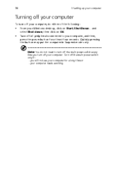
34 3 Setting up your computer Turning on your computer such as the monitor, printer, fax, speakers, etc. To turn on your computer: 1 2 Turn on the rear panel of your computer. Locate and turn the computer on and get to turn on the main power switch on all peripherals connected to your computer After connecting the necessary peripherals and plugging in the power cable, you are now ready to work.
34 3 Setting up your computer Turning on your computer such as the monitor, printer, fax, speakers, etc. To turn on your computer: 1 2 Turn on the rear panel of your computer. Locate and turn the computer on and get to turn on the main power switch on all peripherals connected to your computer After connecting the necessary peripherals and plugging in the power cable, you are now ready to work.
Power Sc User's Guide
Page 46
... at least four seconds. Note: You do either of the following: • • From your Windows desktop, click on OK. you turn off the main power switch only if: - then click on Start, Shut Down...and select Shut down; Turn off all peripherals connected to turn off your computer, and then, press...
... at least four seconds. Note: You do either of the following: • • From your Windows desktop, click on OK. you turn off the main power switch only if: - then click on Start, Shut Down...and select Shut down; Turn off all peripherals connected to turn off your computer, and then, press...

Power Sc User's Guide
Page 57
47 Connector JP7 JP9 Description Power switch connector 1-2: set CN21 as slave 2-3: set CN21 as Master CPU frequency table S4 0 0 0 0 0 0 0 1 S3 0 0 0 0 1 1 1 0 S2 0 0 1 1 0 1 1 0 S1 0 1 0 1 1 0 1 0 CPU 66 100 150 133 100 100 133 66 SDRAM 100 100 100 100 133 150 133 66
47 Connector JP7 JP9 Description Power switch connector 1-2: set CN21 as slave 2-3: set CN21 as Master CPU frequency table S4 0 0 0 0 0 0 0 1 S3 0 0 0 0 1 1 1 0 S2 0 0 1 1 0 1 1 0 S1 0 1 0 1 1 0 1 0 CPU 66 100 150 133 100 100 133 66 SDRAM 100 100 100 100 133 150 133 66


