
Aspire T650/E500 and Power F5 Service Guide
Page 6
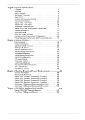
... E500 Front Pane 18 AcerPower F5 Front Panel 19 Aspire T650/E500, AcerPower F5 Rear Panel 20 System Peripherals 21 Acer eRecovery 23 Acer disc-to-disc recovery 25 Hardware Specifications and Configurations 26 Power Management Function (ACPI support function...) . . . . 33 Chapter 2 System Utilities 35 Entering Setup 36 Product Information 37 Standard CMOS Features 38 Primary IDE Master 40 Advanced BIOS...
... E500 Front Pane 18 AcerPower F5 Front Panel 19 Aspire T650/E500, AcerPower F5 Rear Panel 20 System Peripherals 21 Acer eRecovery 23 Acer disc-to-disc recovery 25 Hardware Specifications and Configurations 26 Power Management Function (ACPI support function...) . . . . 33 Chapter 2 System Utilities 35 Entering Setup 36 Product Information 37 Standard CMOS Features 38 Primary IDE Master 40 Advanced BIOS...
Aspire T650/E500 and Power F5 Service Guide
Page 12
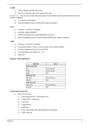
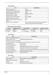
Default is enabled. LAN T T T T Controller : ULI M1573 compatible LAN Chip : Marvell 8EE8001 Should be worked under 10/100/1000 Mbs environment Reserved disabled function on BIOS side. Default is enabled USB T T T T T Controller : ULI M1573 compatible Connectors Quantity : 8 (four on rear connector, four on-board header) 2 for ... solution for multi-media and also user-friendliness for Multi-Media card reader (Pin : 1*5) USB 2.0/1.1 System LED Definition LED Item Power state LED S0 S1/S3 S4/S5 HDD state LED IDE active IDE idle LAN state LED LAN active LAN idle Color Green Steady...
Default is enabled. LAN T T T T Controller : ULI M1573 compatible LAN Chip : Marvell 8EE8001 Should be worked under 10/100/1000 Mbs environment Reserved disabled function on BIOS side. Default is enabled USB T T T T T Controller : ULI M1573 compatible Connectors Quantity : 8 (four on rear connector, four on-board header) 2 for ... solution for multi-media and also user-friendliness for Multi-Media card reader (Pin : 1*5) USB 2.0/1.1 System LED Definition LED Item Power state LED S0 S1/S3 S4/S5 HDD state LED IDE active IDE idle LAN state LED LAN active LAN idle Color Green Steady...

Aspire T650/E500 and Power F5 Service Guide
Page 15
MainBoard Placement Mainboard Items Item 1 2 3 4 5 6 7 8 9 10 11 12 13 14 Label CPU Socket DIMM1,2 IR1 CPU_FAN ATX_POWER BIOS_TBL BIOS_WP FDD IDE2 IDE1 TBD CLR_CMOS SATA1~4 CASE_FAN Description LGA775 socket for Pentium 4 CPUs 240-pin DDR2 SDRAM slots Infrared header CPU cooling fan connector Standard 24-pin ATX power connector BIOS Prevent header BIOS protection jumper Floppy diskette drive connector Secondary IDE channel Primary IDE channel TBD Clear CMOS jumper Serial ATA connectors Case cooling fan connector 8 Chapter 1
MainBoard Placement Mainboard Items Item 1 2 3 4 5 6 7 8 9 10 11 12 13 14 Label CPU Socket DIMM1,2 IR1 CPU_FAN ATX_POWER BIOS_TBL BIOS_WP FDD IDE2 IDE1 TBD CLR_CMOS SATA1~4 CASE_FAN Description LGA775 socket for Pentium 4 CPUs 240-pin DDR2 SDRAM slots Infrared header CPU cooling fan connector Standard 24-pin ATX power connector BIOS Prevent header BIOS protection jumper Floppy diskette drive connector Secondary IDE channel Primary IDE channel TBD Clear CMOS jumper Serial ATA connectors Case cooling fan connector 8 Chapter 1
Aspire T650/E500 and Power F5 Service Guide
Page 18
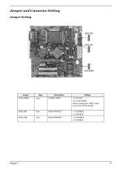
Jumper and Connector Setting Jumper Setting Jumper CLR_CMOS Type 3-pin Description CLEAR CMOS BIOS_WP BIOS_TBL 3-pin 3-pin BIOS PROTECT BIOS PREVENT Setting 1-2: Normal 2-3: Clear CMOS Before clearing the CMOS, make sure to turn off the system. 1-2: DISABLE 2-3: ENABLE 1-2: DISABLE 2-3: ENABLE Chapter 1 11
Jumper and Connector Setting Jumper Setting Jumper CLR_CMOS Type 3-pin Description CLEAR CMOS BIOS_WP BIOS_TBL 3-pin 3-pin BIOS PROTECT BIOS PREVENT Setting 1-2: Normal 2-3: Clear CMOS Before clearing the CMOS, make sure to turn off the system. 1-2: DISABLE 2-3: ENABLE 1-2: DISABLE 2-3: ENABLE Chapter 1 11
Aspire T650/E500 and Power F5 Service Guide
Page 33
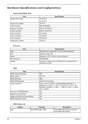
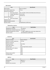
... Processor voltage can be detected by any system without setting any jumper BIOS Item BIOS code programmer BIOS version BIOS ROM size BIOS ROM package Support protocol Boot from CD-ROM feature Support to LS-120 drive Support to BIOS boot block feature BIOS Password Control Specification AMI R01-A0 4MB 32-pin PLCC package PCIX... (VBE/PM V1.1), SMBIOS 2.3, E-IDE 1.1, ACPI 1.0b,ESCD1.03, PnP 1.0a, Bootable CD-ROM 1.0, USB 1.1~ USB 2.0, UHCI 1.0, ANSI ATA 3.0 ATAPI Yes Yes Yes Yes BIOS Hotkey List Hotkey c Function Enter BIOS Setup Utility Description Press while the system is booting to enter...
... Processor voltage can be detected by any system without setting any jumper BIOS Item BIOS code programmer BIOS version BIOS ROM size BIOS ROM package Support protocol Boot from CD-ROM feature Support to LS-120 drive Support to BIOS boot block feature BIOS Password Control Specification AMI R01-A0 4MB 32-pin PLCC package PCIX... (VBE/PM V1.1), SMBIOS 2.3, E-IDE 1.1, ACPI 1.0b,ESCD1.03, PnP 1.0a, Bootable CD-ROM 1.0, USB 1.1~ USB 2.0, UHCI 1.0, ANSI ATA 3.0 ATAPI Yes Yes Yes Yes BIOS Hotkey List Hotkey c Function Enter BIOS Setup Utility Description Press while the system is booting to enter...
Aspire T650/E500 and Power F5 Service Guide
Page 34
...Processor L2 Cache RAM type PBSRAM (Pipelined-burst Synchronous RAM) L2 Cache RAM size Depends on board Enable/Disable by BIOS Setup Chapter 1 27 VRM (Voltage Regulator Module) Function CPU VRM CPU VRM VRM Specification VRM10.1 VRM 9.0 Typical Voltage 0.8375~1.6v... 1.1-1.85 Voltage Power Source 12 Voltage 12 Voltage Maximum Output 101A 70A Cache Memory Item Specification First-Level Cache Configurations Cache function control Enable/Disable by BIOS Setup Second-Level Cache Configurations The information below is only applicable...
...Processor L2 Cache RAM type PBSRAM (Pipelined-burst Synchronous RAM) L2 Cache RAM size Depends on board Enable/Disable by BIOS Setup Chapter 1 27 VRM (Voltage Regulator Module) Function CPU VRM CPU VRM VRM Specification VRM10.1 VRM 9.0 Typical Voltage 0.8375~1.6v... 1.1-1.85 Voltage Power Source 12 Voltage 12 Voltage Maximum Output 101A 70A Cache Memory Item Specification First-Level Cache Configurations Cache function control Enable/Disable by BIOS Setup Second-Level Cache Configurations The information below is only applicable...
Aspire T650/E500 and Power F5 Service Guide
Page 35
... HDD, CD-ROM, CD-RW, DVD-ROM,Combo,DVD burner PIO 0/1/2/3/4 33/66/100/133 2 HDD Yes Yes Enable/Disable by BIOS setup Diskette Drive Interface Item Diskette Drive Controller Diskette Drive Controller Resident Bus Supported Diskette Drive Formats Function Control Specification ULi M1573 LPC Bus ...1.44MB, 2.88MB format and slim type diskette drive Enable/Disable by BIOS Setup Serial Port Item Serial port controller Serial port controller resident bus Number of serial port Serial port location 16550 UART support Connector...
... HDD, CD-ROM, CD-RW, DVD-ROM,Combo,DVD burner PIO 0/1/2/3/4 33/66/100/133 2 HDD Yes Yes Enable/Disable by BIOS setup Diskette Drive Interface Item Diskette Drive Controller Diskette Drive Controller Resident Bus Supported Diskette Drive Formats Function Control Specification ULi M1573 LPC Bus ...1.44MB, 2.88MB format and slim type diskette drive Enable/Disable by BIOS Setup Serial Port Item Serial port controller Serial port controller resident bus Number of serial port Serial port location 16550 UART support Connector...
Aspire T650/E500 and Power F5 Service Guide
Page 41
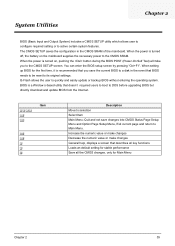
... e ^ Item { } l t u Description Move to selection Select Item Main Menu: Quit and not save the current BIOS to a disk in the CMOS SRAM of the mainboard. When the power is recommended that BIOS needs to be reset to the CMOS SETUP screen. Increase the numeric value or make changes Decrease the... users to boot to Main Menu. Q-Flash allows the user to active certain system features. You can enter the BIOS setup screen by pressing "Ctrl+F1". When the power is a Window s-based utility that describes all key functions Loads an default setting for stable performance Save all the CMOS...
... e ^ Item { } l t u Description Move to selection Select Item Main Menu: Quit and not save the current BIOS to a disk in the CMOS SRAM of the mainboard. When the power is recommended that BIOS needs to be reset to the CMOS SETUP screen. Increase the numeric value or make changes Decrease the... users to boot to Main Menu. Q-Flash allows the user to active certain system features. You can enter the BIOS setup screen by pressing "Ctrl+F1". When the power is a Window s-based utility that describes all key functions Loads an default setting for stable performance Save all the CMOS...

Aspire T650/E500 and Power F5 Service Guide
Page 42
f Product Information f Standard CMOS Setup f Advanced BIOS Features f Advanced Chipset Features f Integrated Peripherals f Power Management Setup f PnP/PCI Configuration f PC Health Status f Frequency Control Load Default Settings Set Supervisor Password Set User Password...the system Save CMOS value settings to Setup Change, set or disable password. Parameter Product Information Standard CMOS Features Advanced BIOS Features Integrated Peripherals Power Management Setup PnP/PCI Configuration PC Health Status Load Default Settings Set Supervisor Password Set User Password Save & Exit Setup...
f Product Information f Standard CMOS Setup f Advanced BIOS Features f Advanced Chipset Features f Integrated Peripherals f Power Management Setup f PnP/PCI Configuration f PC Health Status f Frequency Control Load Default Settings Set Supervisor Password Set User Password...the system Save CMOS value settings to Setup Change, set or disable password. Parameter Product Information Standard CMOS Features Advanced BIOS Features Integrated Peripherals Power Management Setup PnP/PCI Configuration PC Health Status Load Default Settings Set Supervisor Password Set User Password Save & Exit Setup...
Aspire T650/E500 and Power F5 Service Guide
Page 43
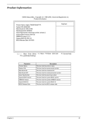
Product Information Product Name: Aspire T650/E500/AP F5 System S/N: 00000000 Main Board ID: ERC410M Main Board S/N: 0000000 Asset Tag Number: Asset tag number: at least 2 System BIOS Version: R01-A3 SMBIOS Version: 2.3.1 System BIOS ID: R01-A3 BIOS Release Date: 06/16/05 Help Item mnlk :Move Enter : ...help F9: Load Default Settings Parameter Product Name System S/N Main Board ID Main Board S/N Asset Tag Number System BIOS Version SMBIOS Version System BIOS ID BIOS Release Date Description This item lists the product name This item lists the system serial number This item lists the ...
Product Information Product Name: Aspire T650/E500/AP F5 System S/N: 00000000 Main Board ID: ERC410M Main Board S/N: 0000000 Asset Tag Number: Asset tag number: at least 2 System BIOS Version: R01-A3 SMBIOS Version: 2.3.1 System BIOS ID: R01-A3 BIOS Release Date: 06/16/05 Help Item mnlk :Move Enter : ...help F9: Load Default Settings Parameter Product Name System S/N Main Board ID Main Board S/N Asset Tag Number System BIOS Version SMBIOS Version System BIOS ID BIOS Release Date Description This item lists the product name This item lists the system serial number This item lists the ...

Aspire T650/E500 and Power F5 Service Guide
Page 44
... set the date following the hour-minutesecond format The items format is display only Month : from 1999 to configure system Time. to Sat., determined by BIOS and is . Standard CMOS Setup System Date System Time fPrimary IDE Master fPrimary IDE Slave fSecondary IDE Master fSecondary IDE Slave fThird IDE Master fThird...
... set the date following the hour-minutesecond format The items format is display only Month : from 1999 to configure system Time. to Sat., determined by BIOS and is . Standard CMOS Setup System Date System Time fPrimary IDE Master fPrimary IDE Slave fSecondary IDE Master fSecondary IDE Slave fThird IDE Master fThird...
Aspire T650/E500 and Power F5 Service Guide
Page 45
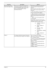
... T Head : Number of heads T Precomp : Write precomp T Landing Zone : Landing Zone T Sector : Number of sectors The category identifies the types of three methods: Auto : Allows BIOS to automatically detect IDE devices during POST (default) None : Select this if no IDE devices are used and the system will skip the automatic detection...
... T Head : Number of heads T Precomp : Write precomp T Landing Zone : Landing Zone T Sector : Number of sectors The category identifies the types of three methods: Auto : Allows BIOS to automatically detect IDE devices during POST (default) None : Select this if no IDE devices are used and the system will skip the automatic detection...
Aspire T650/E500 and Power F5 Service Guide
Page 47
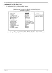
Copyright (C) 1985-2004, American Megatrends, Inc. Advanced BIOS Features Virus Warning Silent Boot Confuguration Table Quick Power On Self Test fRemovable Drives fHard Disk Drives fCD/DVD Drives First Boot Device Second Boot Device Third Boot Device Boot Other Device Boot Up ...:SS-PIONEER] [Enabled] [On] [Enabled] [Enabled] mnlk :Move Enter : Select +/-/: Value F10: Save ESC: Exit F9: Load Default Settings F1: General help Chapter 2 41 Advanced BIOS Features The following screen shows the Advanced...
Copyright (C) 1985-2004, American Megatrends, Inc. Advanced BIOS Features Virus Warning Silent Boot Confuguration Table Quick Power On Self Test fRemovable Drives fHard Disk Drives fCD/DVD Drives First Boot Device Second Boot Device Third Boot Device Boot Other Device Boot Up ...:SS-PIONEER] [Enabled] [On] [Enabled] [Enabled] mnlk :Move Enter : Select +/-/: Value F10: Save ESC: Exit F9: Load Default Settings F1: General help Chapter 2 41 Advanced BIOS Features The following screen shows the Advanced...
Aspire T650/E500 and Power F5 Service Guide
Page 48
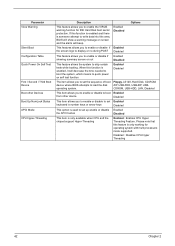
...allows you to enable the VIRUS warning function for operating system with multi processors mode supported. Parameter Virus Warning Silent Boot Configuration Table Quick Power On Self Test First / Second / Third Boot Device Boot other device Disabled This item allows you to enable or disable to set ... CPU Hyper Threading 42 Chapter 2 operating system. If this function is enabled and there is someone attempt to write data into this area, BIOS will show a warning message on self test function Enabled Disabled The item allows you to enable or disable if showing summary screen or not ...
...allows you to enable the VIRUS warning function for operating system with multi processors mode supported. Parameter Virus Warning Silent Boot Configuration Table Quick Power On Self Test First / Second / Third Boot Device Boot other device Disabled This item allows you to enable or disable to set ... CPU Hyper Threading 42 Chapter 2 operating system. If this function is enabled and there is someone attempt to write data into this area, BIOS will show a warning message on self test function Enabled Disabled The item allows you to enable or disable if showing summary screen or not ...
Aspire T650/E500 and Power F5 Service Guide
Page 50
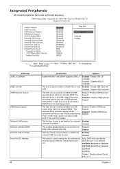
... keyboard command and lets you use a USB mouse during POST or after boot if you enable or disable the USB mouse driver within the onboard BIOS. Integrated Peripherals All onboard peripherals can be set whether the onboard Enabled LAN card is used to enable or disable the on-chip Enabled : Enable... USB Controller USB Disabled : Disable USB Controller This item lets you enable or disable the USB keyboard driver within the onboard BIOS. The keyboard driver is used to assign the I/O address and interrupt request (IRQ) for onboard serial port 1 or 2 Auto...
... keyboard command and lets you use a USB mouse during POST or after boot if you enable or disable the USB mouse driver within the onboard BIOS. Integrated Peripherals All onboard peripherals can be set whether the onboard Enabled LAN card is used to enable or disable the on-chip Enabled : Enable... USB Controller USB Disabled : Disable USB Controller This item lets you enable or disable the USB keyboard driver within the onboard BIOS. The keyboard driver is used to assign the I/O address and interrupt request (IRQ) for onboard serial port 1 or 2 Auto...

Aspire T650/E500 and Power F5 Service Guide
Page 56
... the EMI(ElectroMagnetic Interference) generated by the system. 50 Chapter 2 This item indicates the ratio actual value of this motherboard When this item is enabled, BIOS will disable the clock signal of the motherboard. Frequency Control This page helps you to set up the frequency control of free PCI slots If...
... the EMI(ElectroMagnetic Interference) generated by the system. 50 Chapter 2 This item indicates the ratio actual value of this motherboard When this item is enabled, BIOS will disable the clock signal of the motherboard. Frequency Control This page helps you to set up the frequency control of free PCI slots If...

Aspire T650/E500 and Power F5 Service Guide
Page 57
Press and then to install the defaults. If you install optimized defaults for all appropriate items in the Setup Utility. Chapter 2 51 detects. Load Default Settings Selecting the field loads the factory defaults for a specific option, select and display that lets you only want to install setup dafaults for BIOS and Chipset Features which the system automatically. THis option opens a dialog box that option, and then press. Press and then to not install the defaults.
Press and then to install the defaults. If you install optimized defaults for all appropriate items in the Setup Utility. Chapter 2 51 detects. Load Default Settings Selecting the field loads the factory defaults for a specific option, select and display that lets you only want to install setup dafaults for BIOS and Chipset Features which the system automatically. THis option opens a dialog box that option, and then press. Press and then to not install the defaults.

Aspire T650/E500 and Power F5 Service Guide
Page 58
... "Setup" at the center of the screen to assist you in "Security Option" of "BIOS Features Setup" menu, you will be promped for the password only when you try to enter BIOS Setup. A message will be prompted for the password every time the system reboots or any ...Chapter 2 You may also press to eight characters, and press. To disable password, just press when you system or entering BIOS Setup but can not modify any previously entered password from "BIOS Features Setup" menu, you have selected "System" in creating a password. Also you are prompted to enter password.
... "Setup" at the center of the screen to assist you in "Security Option" of "BIOS Features Setup" menu, you will be promped for the password only when you try to enter BIOS Setup. A message will be prompted for the password every time the system reboots or any ...Chapter 2 You may also press to eight characters, and press. To disable password, just press when you system or entering BIOS Setup but can not modify any previously entered password from "BIOS Features Setup" menu, you have selected "System" in creating a password. Also you are prompted to enter password.


