

Aspire T650/E500 and Power F5 Service Guide
Page 5
... regional offices or the responsible personnel/channel to order FRU parts for repair and service of a machine (e.g. You MUST use the list provided by your Acer office may have decided to the BASIC CONFIGURATION decided for whatever reason, a part number change is made, it supports, please read the following general information... local market requirements and enhance product competitiveness, your regional office MAY have a DIFFERENT part number code to -date information available on card, modem, or extra memory capability). If, for Acer's "global" product offering.
... regional offices or the responsible personnel/channel to order FRU parts for repair and service of a machine (e.g. You MUST use the list provided by your Acer office may have decided to the BASIC CONFIGURATION decided for whatever reason, a part number change is made, it supports, please read the following general information... local market requirements and enhance product competitiveness, your regional office MAY have a DIFFERENT part number code to -date information available on card, modem, or extra memory capability). If, for Acer's "global" product offering.
Aspire T650/E500 and Power F5 Service Guide
Page 8
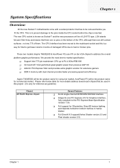
.... Please refer below table for more details address toward each chipset that there are still contact surfaces - These two models (Aspire T650/E500 & AcerPower F5) use ATI on the bottom of the CPU, although there are no less 775 of them. Chapter 1 System Specifications Overview All the new Socket-T...mainstream CPU up to P4 4.0Ghz/FSB 800 T On board ATI VGA performed great graphic power than previous AGP 8X T Add-On PCI-Express VGA card provides extra graphic solution for extensive gamers T DDR II memory with a socket protector that has to be used in this is known as guideline) ...
.... Please refer below table for more details address toward each chipset that there are still contact surfaces - These two models (Aspire T650/E500 & AcerPower F5) use ATI on the bottom of the CPU, although there are no less 775 of them. Chapter 1 System Specifications Overview All the new Socket-T...mainstream CPU up to P4 4.0Ghz/FSB 800 T On board ATI VGA performed great graphic power than previous AGP 8X T Add-On PCI-Express VGA card provides extra graphic solution for extensive gamers T DDR II memory with a socket protector that has to be used in this is known as guideline) ...
Aspire T650/E500 and Power F5 Service Guide
Page 13
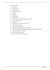
T On-Board Connectors T 1 CPU Socket T 2 Memory Socket T 1 PCI Express x1 Slot T 1 PCI Express x16 Slot T 2 PCI Slots T 1 FDD Slot T 2 PATA IDE Slots T 2 SATA IDE Slots T 1 2*5 pin Intel FPIO sepecification USB pin ... connector (CD-ROM Audio Input) T 1 3/4 pin CPU Fan connector T 1 3 pin System FAN connectors T 1 24pin/4pin ATX interface PS3/PS2 SPS connector T 1 2*4pin Intel FPIO specification Power Switch/Power State LED/HDD active LED T 1 2 pin LAN activity monitor connector T 2 reserved 2pin GPIO connector T Color management for on board connector 6 Chapter 1
T On-Board Connectors T 1 CPU Socket T 2 Memory Socket T 1 PCI Express x1 Slot T 1 PCI Express x16 Slot T 2 PCI Slots T 1 FDD Slot T 2 PATA IDE Slots T 2 SATA IDE Slots T 1 2*5 pin Intel FPIO sepecification USB pin ... connector (CD-ROM Audio Input) T 1 3/4 pin CPU Fan connector T 1 3 pin System FAN connectors T 1 24pin/4pin ATX interface PS3/PS2 SPS connector T 1 2*4pin Intel FPIO specification Power Switch/Power State LED/HDD active LED T 1 2 pin LAN activity monitor connector T 2 reserved 2pin GPIO connector T Color management for on board connector 6 Chapter 1
Aspire T650/E500 and Power F5 Service Guide
Page 33
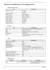
Hardware Specifications and Configurations System Board Major Chip Item System Core Logic Super I/O Controller LAN Controller Memory Controller E-IDE Controller RJ45 Controller Audio Controller VGA Controller Keyboard Controller ATI RC410 ULI M1573 ITE 8712 Marvell 8EE8001 Build in ATI RC410 Build in ...
Hardware Specifications and Configurations System Board Major Chip Item System Core Logic Super I/O Controller LAN Controller Memory Controller E-IDE Controller RJ45 Controller Audio Controller VGA Controller Keyboard Controller ATI RC410 ULI M1573 ITE 8712 Marvell 8EE8001 Build in ATI RC410 Build in ...
Aspire T650/E500 and Power F5 Service Guide
Page 34
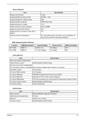
...VRM CPU VRM VRM Specification VRM10.1 VRM 9.0 Typical Voltage 0.8375~1.6v 1.1-1.85 Voltage Power Source 12 Voltage 12 Voltage Maximum Output 101A 70A Cache Memory Item Specification First-Level Cache Configurations Cache function control Enable/Disable by BIOS Setup Second-...L2 Cache function control Enable/Disable by BIOS Setup Chapter 1 27 System Memory Item Memory Slot Number Supported Memory Size per Slot Supported Maximum Memory Size Supported Memory Speed Supported memory voltage Support memory module package Support to parity check feature Support to system installed with ...
...VRM CPU VRM VRM Specification VRM10.1 VRM 9.0 Typical Voltage 0.8375~1.6v 1.1-1.85 Voltage Power Source 12 Voltage 12 Voltage Maximum Output 101A 70A Cache Memory Item Specification First-Level Cache Configurations Cache function control Enable/Disable by BIOS Setup Second-...L2 Cache function control Enable/Disable by BIOS Setup Chapter 1 27 System Memory Item Memory Slot Number Supported Memory Size per Slot Supported Maximum Memory Size Supported Memory Speed Supported memory voltage Support memory module package Support to parity check feature Support to system installed with ...

Aspire T650/E500 and Power F5 Service Guide
Page 36
... Disabled Thermal Design Item Thermal Design Description T Dynamic FAN speed control by hardware monitor T CPU Over-temperature (over 120oC) power off protection. Power On / Wake-up Event Item Power On/ Wake-Up Event Description T Power Button: S1/S3/S4/S5 T PS/2 Keyboard: S1/S3/S4/S5 T USB Keyboard: S1/S3/S4/S5 T ...RTC: S1/S5 T LAN: S1/S3/S5 T Modem (Ring): S1/S3/S5 Memory Address Map Address 0000000 - 009FFFF 00A0000-00BFFFF Size 640 KB System Memory 128 KB Video RAM 00C0000-...
... Disabled Thermal Design Item Thermal Design Description T Dynamic FAN speed control by hardware monitor T CPU Over-temperature (over 120oC) power off protection. Power On / Wake-up Event Item Power On/ Wake-Up Event Description T Power Button: S1/S3/S4/S5 T PS/2 Keyboard: S1/S3/S4/S5 T USB Keyboard: S1/S3/S4/S5 T ...RTC: S1/S5 T LAN: S1/S3/S5 T Modem (Ring): S1/S3/S5 Memory Address Map Address 0000000 - 009FFFF 00A0000-00BFFFF Size 640 KB System Memory 128 KB Video RAM 00C0000-...

Aspire T650/E500 and Power F5 Service Guide
Page 53
...from S3 sleep state. If the item is s power-down . Disabled : Disable Power On by Ring function Enabled : Enable Power On by Alarm" item to enabled and key in which power is saved to essential components such as main memory and wake-capable devices and all system context. ...hardware maintains all system context is supplied only to main memory. Date (of the USB devices Enabled to Instant-Off, then the power button causes a software power down button then power off : Press down . Instand-off instantly Delay 4 Sec. : Press power button 4 sec. S1(POS): The S1 sleep mode...
...from S3 sleep state. If the item is s power-down . Disabled : Disable Power On by Ring function Enabled : Enable Power On by Alarm" item to enabled and key in which power is saved to essential components such as main memory and wake-capable devices and all system context. ...hardware maintains all system context is supplied only to main memory. Date (of the USB devices Enabled to Instant-Off, then the power button causes a software power down button then power off : Press down . Instand-off instantly Delay 4 Sec. : Press power button 4 sec. S1(POS): The S1 sleep mode...

Aspire T650/E500 and Power F5 Service Guide
Page 58
... and you are prompted to enter password. Set Supervisor/User Password When this function is selected, the following message appears at "Security Option" from CMOS memory. Supervisor Password has higher priority than User Password. You may also press to eight characters, and press. If you have selected "System" in creating a password...
... and you are prompted to enter password. Set Supervisor/User Password When this function is selected, the following message appears at "Security Option" from CMOS memory. Supervisor Password has higher priority than User Password. You may also press to eight characters, and press. If you have selected "System" in creating a password...

Aspire T650/E500 and Power F5 Service Guide
Page 68
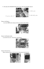
FDD cable P1 power cable ODD IDE cable Remove the Memory Loose the DIMM Latch and pop out the two memory shown bellow. 11. Disconnect the ODD&FDD IDE and P1 power cable from the M/B connector. Remove the front bezel Release the three latches on the front bezel, then remove the front bezel. 62 Remove the Heatsink module. Loosen the four screws , then remove the Heatsink.
FDD cable P1 power cable ODD IDE cable Remove the Memory Loose the DIMM Latch and pop out the two memory shown bellow. 11. Disconnect the ODD&FDD IDE and P1 power cable from the M/B connector. Remove the front bezel Release the three latches on the front bezel, then remove the front bezel. 62 Remove the Heatsink module. Loosen the four screws , then remove the Heatsink.
Aspire T650/E500 and Power F5 Service Guide
Page 75
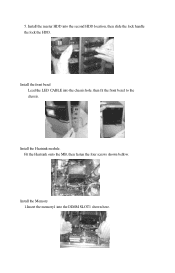
Fit the Heatsink onto the MB, then fasten the four screws shown bellow. Install the Heatsink module. Install the master HDD into the DIMM SLOT1 shown here. Install the Memory 1.Insert the memory1 into the second HDD location, then slide the lock handle the lock the HDD. 5. Install the front bezel Lead the LED CABLE into the chassis hole, then fit the front bezel to the chassis.
Fit the Heatsink onto the MB, then fasten the four screws shown bellow. Install the Heatsink module. Install the master HDD into the DIMM SLOT1 shown here. Install the Memory 1.Insert the memory1 into the second HDD location, then slide the lock handle the lock the HDD. 5. Install the front bezel Lead the LED CABLE into the chassis hole, then fit the front bezel to the chassis.

Aspire T650/E500 and Power F5 Service Guide
Page 85
Remove the front bezel 1. FDD cable P1 power cable ODD IDE cable Remove the Memory Loose the DIMM Latch and pop out the two memory shown bellow. Loosen the four screws , then remove the Heatsink. 11. Disconnect the ODD&FDD IDE and P1 power cable from the M/B connector. Release the three latches on the front bezel, then remove the front bezel. Remove the Heatsink module.
Remove the front bezel 1. FDD cable P1 power cable ODD IDE cable Remove the Memory Loose the DIMM Latch and pop out the two memory shown bellow. Loosen the four screws , then remove the Heatsink. 11. Disconnect the ODD&FDD IDE and P1 power cable from the M/B connector. Release the three latches on the front bezel, then remove the front bezel. Remove the Heatsink module.

Aspire T650/E500 and Power F5 Service Guide
Page 93
Connect the system fan power cable to the M/B connector. Install the Memory 1.Insert the memory1 into the DIMM SLOT1 shown here. 2.Insert the memory2 into the DIMM SLOT2 shown here. Connect the ODD&FDD IDE and P1 power cable to the M/B Connector. FDD cable P1 power cable ODD IDE cable 2. Connect the Cables 1.
Connect the system fan power cable to the M/B connector. Install the Memory 1.Insert the memory1 into the DIMM SLOT1 shown here. 2.Insert the memory2 into the DIMM SLOT2 shown here. Connect the ODD&FDD IDE and P1 power cable to the M/B Connector. FDD cable P1 power cable ODD IDE cable 2. Connect the Cables 1.
Aspire T650/E500 and Power F5 Service Guide
Page 102
11. Remove the front bezel Release the three latches on the front bezel, then remove the front bezel. FDD cable P1 power cable ODD IDE cable Remove the Memory Loose the DIMM Latch and pop out the two memory shown bellow. Remove the Heatsink module. Disconnect the ODD&FDD IDE and P1 power cable from the M/B connector. Loosen the four screws , then remove the Heatsink.
11. Remove the front bezel Release the three latches on the front bezel, then remove the front bezel. FDD cable P1 power cable ODD IDE cable Remove the Memory Loose the DIMM Latch and pop out the two memory shown bellow. Remove the Heatsink module. Disconnect the ODD&FDD IDE and P1 power cable from the M/B connector. Loosen the four screws , then remove the Heatsink.

Aspire T650/E500 and Power F5 Service Guide
Page 109
Install the Heatsink module. 5. Install the master HDD into the DIMM SLOT1 shown here. Fit the Heatsink onto the MB, then fasten the four screws shown bellow. Install the Memory 1.Insert the memory1 into the second HDD location, then slide the lock handle the lock the HDD. Install the front bezel Lead the LED CABLE into the chassis hole, then fit the front bezel to the chassis.
Install the Heatsink module. 5. Install the master HDD into the DIMM SLOT1 shown here. Fit the Heatsink onto the MB, then fasten the four screws shown bellow. Install the Memory 1.Insert the memory1 into the second HDD location, then slide the lock handle the lock the HDD. Install the front bezel Lead the LED CABLE into the chassis hole, then fit the front bezel to the chassis.

Aspire T650 User's Guide EN
Page 8
English 4 System Features Your computer features: Performance • Intel® Pentium® 4 Socket LGA775 CPU • System Memory DDRII 400/533 DIMM, 4 DDR DIMM Slots, expandable to 4GB • Power management functions • 3.5 inch floppy drive / card reader (optional) • CD-ROM, DVD-ROM, CD-RW (52X/24X), DVD/CD-RW combo or...
English 4 System Features Your computer features: Performance • Intel® Pentium® 4 Socket LGA775 CPU • System Memory DDRII 400/533 DIMM, 4 DDR DIMM Slots, expandable to 4GB • Power management functions • 3.5 inch floppy drive / card reader (optional) • CD-ROM, DVD-ROM, CD-RW (52X/24X), DVD/CD-RW combo or...
Aspire T650 User's Guide EN
Page 11
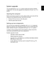
Before you choose new components, please ask your authorized Acer dealer whether the part is compatible with Aspire T650A computers. Opening the computer ...components. Possible upgrades include: - Install additional interface cards in empty PCI slots e.g., PCI fax/modem card Expand high-level memory - In order to High Capacity HDD - You can also upgrade the components of your new components. English 7 System ... side panel. • Slide the panel back and off the computer and unplug the power cord from a CD-ROM drive to CD-RW, DVD-ROM, DVD/CDRW combo or DVD writer -
Before you choose new components, please ask your authorized Acer dealer whether the part is compatible with Aspire T650A computers. Opening the computer ...components. Possible upgrades include: - Install additional interface cards in empty PCI slots e.g., PCI fax/modem card Expand high-level memory - In order to High Capacity HDD - You can also upgrade the components of your new components. English 7 System ... side panel. • Slide the panel back and off the computer and unplug the power cord from a CD-ROM drive to CD-RW, DVD-ROM, DVD/CDRW combo or DVD writer -


