
Power F1/ Aspire T310 Service Guide
Page 16
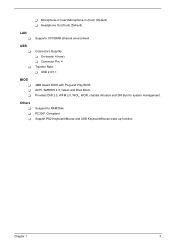
Provides DMI 2.0, WFM 2.0, WOL, WOR, chassis intrusion and SM Bus for system management. Others T T T Suspend to RAM/Disk PC2001 Compliant Support PS2 Keyboard/Mouse and USB Keyboard/Mouse wake up function Chapter 1 3 T Microphone-in (rear)/Microphone-in (front) (Default) T Headphone Out (front) (Default) LAN T Supports 10/100MB ethernet environment USB T T Connectors Quantity: T On-board: 4 (rear) T Connector Pin: 4 Transfer Rate: T USB 2.0/1.1 BIOS T T T 4MB Award BIOS with Plug and Play BIOS ACPI, SMBIOS 2.3, Green and Boot Block.
Provides DMI 2.0, WFM 2.0, WOL, WOR, chassis intrusion and SM Bus for system management. Others T T T Suspend to RAM/Disk PC2001 Compliant Support PS2 Keyboard/Mouse and USB Keyboard/Mouse wake up function Chapter 1 3 T Microphone-in (rear)/Microphone-in (front) (Default) T Headphone Out (front) (Default) LAN T Supports 10/100MB ethernet environment USB T T Connectors Quantity: T On-board: 4 (rear) T Connector Pin: 4 Transfer Rate: T USB 2.0/1.1 BIOS T T T 4MB Award BIOS with Plug and Play BIOS ACPI, SMBIOS 2.3, Green and Boot Block.

Power F1/ Aspire T310 Service Guide
Page 22
... 64MB~1G 64MB~1G 2G Cache Memory Item First-Level Cache Configurations Cache function control Second-Level Cache Configurations L2 Cache RAM type L2 Cache RAM size L2 Cache RAM speed L2 Cache RAM voltage L2 Cache function control L2 Cache scheme Specification Enable/Disable by BIOS Setup PBSRAM Celeron: 128K Intel P4: 256K...
... 64MB~1G 64MB~1G 2G Cache Memory Item First-Level Cache Configurations Cache function control Second-Level Cache Configurations L2 Cache RAM type L2 Cache RAM size L2 Cache RAM speed L2 Cache RAM voltage L2 Cache function control L2 Cache scheme Specification Enable/Disable by BIOS Setup PBSRAM Celeron: 128K Intel P4: 256K...
Power F1/ Aspire T310 Service Guide
Page 30
... you exit Setup. NOTE: If you have saved all open files. The Setup program loads configuration values into the battery-backed nonvolatile memory called CMOS RAM. In this case, the system cannot retain configuration values in CMOS. Chapter 2 17 This memory area is no need to run Setup, make sure that...
... you exit Setup. NOTE: If you have saved all open files. The Setup program loads configuration values into the battery-backed nonvolatile memory called CMOS RAM. In this case, the system cannot retain configuration values in CMOS. Chapter 2 17 This memory area is no need to run Setup, make sure that...
Power F1/ Aspire T310 Service Guide
Page 37
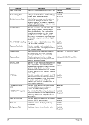
... whether the BIOS will be Enabled copied to Enabled will swap floppy drive a: and Enabled b:. When Normal is selected, A20 is On powered on . Non-OS2 OS2 HDD S.M.A.R.T Capability The S.M.A.R.T (Self-Monitoring, Analysis, and Reporting Technology) system is controlled by a keyboard controller... chipset hardware. Enabled Disabled Configuration Table Enables or disables the configuration table. Parameter Description Options Swap Floppy Drive Setting to RAM for faster execution. A20 refers to On will allows users to select the delay between when the key was first pressed...
... whether the BIOS will be Enabled copied to Enabled will swap floppy drive a: and Enabled b:. When Normal is selected, A20 is On powered on . Non-OS2 OS2 HDD S.M.A.R.T Capability The S.M.A.R.T (Self-Monitoring, Analysis, and Reporting Technology) system is controlled by a keyboard controller... chipset hardware. Enabled Disabled Configuration Table Enables or disables the configuration table. Parameter Description Options Swap Floppy Drive Setting to RAM for faster execution. A20 refers to On will allows users to select the delay between when the key was first pressed...

Power F1/ Aspire T310 Service Guide
Page 39
... Description Shows the CPU and DRAM frequency. This item allows you change specifications of the installed DRAM or the installed CPU. Techniques such as the RAM Access (data read or write and starting another from the same (non-page mode) DRAM. Auto, 1x, 2x, 4x ,8x 26 Chapter ...: Parameter AGP Aperture Size Graphic Window WR Combin AGP Fast Write Support AGP Data Rate Description Options This setting controls just how much system RAM can be allocated to set the amount of Page Mode DRAM are presented below. Enabled Disabled Enables you to a DRAM is the amount ...
... Description Shows the CPU and DRAM frequency. This item allows you change specifications of the installed DRAM or the installed CPU. Techniques such as the RAM Access (data read or write and starting another from the same (non-page mode) DRAM. Auto, 1x, 2x, 4x ,8x 26 Chapter ...: Parameter AGP Aperture Size Graphic Window WR Combin AGP Fast Write Support AGP Data Rate Description Options This setting controls just how much system RAM can be allocated to set the amount of Page Mode DRAM are presented below. Enabled Disabled Enables you to a DRAM is the amount ...

Power F1/ Aspire T310 Service Guide
Page 40
OnChip AGP Control Press [Enter] to enter the sub-menu and the following screen appears: Parameter VGA Share Memory Size Description Selects the VGA share memory size Options 16, 32MB, 64MB, 128MB Parameter System BIOS Cacheable Video RAM Cacheable Description Options Enables or disables the system BIOS cacheable. Disabled Enabled Enables or disables the video RAM cacheable. Disabled Enabled Chapter 2 27
OnChip AGP Control Press [Enter] to enter the sub-menu and the following screen appears: Parameter VGA Share Memory Size Description Selects the VGA share memory size Options 16, 32MB, 64MB, 128MB Parameter System BIOS Cacheable Video RAM Cacheable Description Options Enables or disables the system BIOS cacheable. Disabled Enabled Enables or disables the video RAM cacheable. Disabled Enabled Chapter 2 27
Power F1/ Aspire T310 Service Guide
Page 69
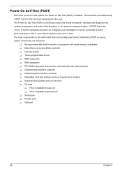
... Memory Access (DMA) controller T Interrupt system T Three programmable timers T ROM subsystem T RAM subsystem T RTC RAM subsystem and real time clock/calendar with built-in system operations at port 80h or even halts the system if the error is fatal. Power-On Self-Test (POST) Each time you turn on the system, the... Power-on screen, generates a check point code at power-on, it displays ...
... Memory Access (DMA) controller T Interrupt system T Three programmable timers T ROM subsystem T RAM subsystem T RTC RAM subsystem and real time clock/calendar with built-in system operations at port 80h or even halts the system if the error is fatal. Power-On Self-Test (POST) Each time you turn on the system, the... Power-on screen, generates a check point code at power-on, it displays ...

Power F1/ Aspire T310 Service Guide
Page 70
... 05h 06h 07h 08h 09h 0Ah 0Bh 0Ch 0Dh 0Eh 0Fh 10h 11h Description Test CMOS R/W functionality Early chipset initialization: • Disable shadow RAM • Disable L2 Cache (socket 7 or below) • Program basic chipset registers Detect memory • Auto-detection of DRAM size, ... the stages it is R/W-able or not. A unique check point number represents each task. keep beeping the speaker. The following table describes the Acer common tasks carried out by a port & interface swap (optional) 3. Reset keyboard for Winbond 977 series Super I /O chips 2. Auto detect ports...
... 05h 06h 07h 08h 09h 0Ah 0Bh 0Ch 0Dh 0Eh 0Fh 10h 11h Description Test CMOS R/W functionality Early chipset initialization: • Disable shadow RAM • Disable L2 Cache (socket 7 or below) • Program basic chipset registers Detect memory • Auto-detection of DRAM size, ... the stages it is R/W-able or not. A unique check point number represents each task. keep beeping the speaker. The following table describes the Acer common tasks carried out by a port & interface swap (optional) 3. Reset keyboard for Winbond 977 series Super I /O chips 2. Auto detect ports...

Power F1/ Aspire T310 Service Guide
Page 76
...On Board Serial Port 2 Conflict(s) Action/FRU 1. System board. 1. System board 1. Enter BIOS Setup and load the default settings. 3. Remove all power supply voltages, switch, and jumper settings before you did receive a POST error message, use "POST Error Messages List" to replace an FRU, and ...Real Time Clock Error CMOS Battery Bad CMOS Checksum Error Equipment Configuration Error System Management Memory Bad Memory Error at MMMM:SSSS:OOOOh RAM Parity Error PS/2 Keyboard Error or Keyboard Not Connected PS/2 Keyboard Interface Error PS/2 Keyboard Locked Onboard xxx... System board. 1....
...On Board Serial Port 2 Conflict(s) Action/FRU 1. System board. 1. System board 1. Enter BIOS Setup and load the default settings. 3. Remove all power supply voltages, switch, and jumper settings before you did receive a POST error message, use "POST Error Messages List" to replace an FRU, and ...Real Time Clock Error CMOS Battery Bad CMOS Checksum Error Equipment Configuration Error System Management Memory Bad Memory Error at MMMM:SSSS:OOOOh RAM Parity Error PS/2 Keyboard Error or Keyboard Not Connected PS/2 Keyboard Interface Error PS/2 Keyboard Locked Onboard xxx... System board. 1....


