
PD115 Service Guide
Page 14
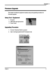
Setup Tool / Equipment 1. Chapter 2 Firmware Upgrade This chapter provides the equipment needed, setup and upgrading procedure for Firmware upgrade. USB Cable (see right picture) 3. Connect Download Cable to projector 2. Power Coard Upgrading Procedure 1. Open burning programma (DLP Composer Lite) Chapter 2 8 Computer 2.
Setup Tool / Equipment 1. Chapter 2 Firmware Upgrade This chapter provides the equipment needed, setup and upgrading procedure for Firmware upgrade. USB Cable (see right picture) 3. Connect Download Cable to projector 2. Power Coard Upgrading Procedure 1. Open burning programma (DLP Composer Lite) Chapter 2 8 Computer 2.
PD115 Service Guide
Page 15
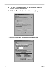
Click the Start Download button and then start to burning of Burning than remove Power Cord and Burning Cord . 9 Chapter 2 Completion of program . 5. 3. Press Power and Menu button together and connect the power cord into the projector . Than release these 2 bottoms . 4.
Click the Start Download button and then start to burning of Burning than remove Power Cord and Burning Cord . 9 Chapter 2 Completion of program . 5. 3. Press Power and Menu button together and connect the power cord into the projector . Than release these 2 bottoms . 4.
PD115 Service Guide
Page 19
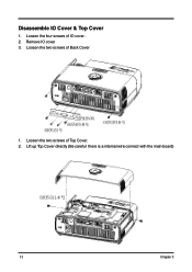
Loosen the four screws of Top Cover. 2. Loosen the two screws of IO cover. 2. Lift up Top Cover directly (Be careful there is a internal wire connect with the main board) 13 Chapter 3 Disassemble IO Cover & Top Cover 1. Remove IO cover 3. Loosen the two screws of Back Cover 1.
Loosen the four screws of Top Cover. 2. Loosen the two screws of IO cover. 2. Lift up Top Cover directly (Be careful there is a internal wire connect with the main board) 13 Chapter 3 Disassemble IO Cover & Top Cover 1. Remove IO cover 3. Loosen the two screws of Back Cover 1.
PD115 Service Guide
Page 20
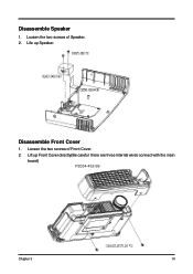
Disassemble Front Cover 1. Loosen the two screws of Speaker. 2. Life up Front Cover directly(Be careful there are three internal wires connect with the main board) P2034-452-99 Chapter 3 14 Loosen the two screws of Front Cover. 2. Lift up Speaker. Disassemble Speaker 1.
Disassemble Front Cover 1. Loosen the two screws of Speaker. 2. Life up Front Cover directly(Be careful there are three internal wires connect with the main board) P2034-452-99 Chapter 3 14 Loosen the two screws of Front Cover. 2. Lift up Speaker. Disassemble Speaker 1.
PD115 Service Guide
Page 37
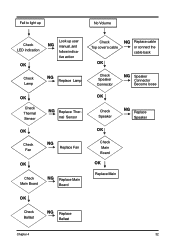
mal Sensor OK Check Speaker NG Replace Speaker OK OK Check Fan NG Replace Fan OK Check Main Board NG Replace Main Board Check Main Board OK Replace Main OK Check Ballast NG Replace Ballast Chapter 4 32 Fail to light up No Volume Check LED indication OK Look up user NG manual ,and follow indica- tive action Check Lamp NG Replace Lamp Check Top cover's cable NG Replace cable or connect the cable back OK Check Speaker Connector NG Speaker Connector Become loose OK Check Thermal Sensor NG Replace Ther-
mal Sensor OK Check Speaker NG Replace Speaker OK OK Check Fan NG Replace Fan OK Check Main Board NG Replace Main Board Check Main Board OK Replace Main OK Check Ballast NG Replace Ballast Chapter 4 32 Fail to light up No Volume Check LED indication OK Look up user NG manual ,and follow indica- tive action Check Lamp NG Replace Lamp Check Top cover's cable NG Replace cable or connect the cable back OK Check Speaker Connector NG Speaker Connector Become loose OK Check Thermal Sensor NG Replace Ther-
PD115 Service Guide
Page 39
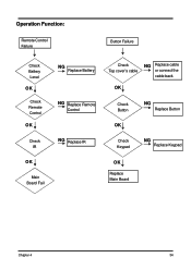
Operation Function: Remote Control Failure Button Failure Check Battery Level OK Check Remote Control OK Check IR OK Main Board Fail NG Replace Battery NG Replace Remote Control NG Replace IR Check Top cover's cable NG Replace cable or connect the cable back OK Check Button OK NG Replace Button Check Keypad NG Replace Keypad OK Replace Main Board Chapter 4 34
Operation Function: Remote Control Failure Button Failure Check Battery Level OK Check Remote Control OK Check IR OK Main Board Fail NG Replace Battery NG Replace Remote Control NG Replace IR Check Top cover's cable NG Replace cable or connect the cable back OK Check Button OK NG Replace Button Check Keypad NG Replace Keypad OK Replace Main Board Chapter 4 34
PD115 User's Guide EN
Page 1
English Table of Contents Table of Contents 1 Usage Notice 2 Precautions ...2 Introduction 4 Product Features 4 Package Overview 5 Product Overview 6 Main Unit ...6 Control Panel ...7 Connection Ports ...8 Remote Control with Laser Pointer 9 Installation 10 Connecting the Projector 10 Powering On/Off the Projector 11 Powering On the Projector 11 Powering Off the projector 12 Warning Indicator ...12...
English Table of Contents Table of Contents 1 Usage Notice 2 Precautions ...2 Introduction 4 Product Features 4 Package Overview 5 Product Overview 6 Main Unit ...6 Control Panel ...7 Connection Ports ...8 Remote Control with Laser Pointer 9 Installation 10 Connecting the Projector 10 Powering On/Off the Projector 11 Powering On the Projector 11 Powering Off the projector 12 Warning Indicator ...12...

PD115 User's Guide EN
Page 4
... addressable pixels ‹ Single chip DLPTM technology ‹ NTSC 3.58/NTSC 4.43/PAL/SECAM and HDTV compatible (480i/p, 576i/p, 720p, 1080i) ‹ High-tech DVI connection for digital signal with HDCP function and supports 480p, 576p, 720p and 1080i (Optional) ‹ Full function remote control with laser pointer ‹ User friendly...
... addressable pixels ‹ Single chip DLPTM technology ‹ NTSC 3.58/NTSC 4.43/PAL/SECAM and HDTV compatible (480i/p, 576i/p, 720p, 1080i) ‹ High-tech DVI connection for digital signal with HDCP function and supports 480p, 576p, 720p and 1080i (Optional) ‹ Full function remote control with laser pointer ‹ User friendly...
PD115 User's Guide EN
Page 6
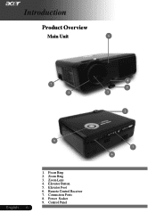
Zoom Ring 3. Zoom Lens 4. Introduction Product Overview Main Unit 6 7 1 4 5 3 2 9 English ... 6 1. Remote Control Receiver 7. Control Panel 7 6 Elevator Button 5. Power Socket 9. Elevator Foot 6. Connection Ports 8. Focus Ring 2.
Zoom Ring 3. Zoom Lens 4. Introduction Product Overview Main Unit 6 7 1 4 5 3 2 9 English ... 6 1. Remote Control Receiver 7. Control Panel 7 6 Elevator Button 5. Power Socket 9. Elevator Foot 6. Connection Ports 8. Focus Ring 2.
PD115 User's Guide EN
Page 8
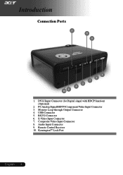
RS232 Connector 6. Introduction Connection Ports 5 8 6 10 9 1 2 7 3 4 1. Remote Control Receiver 10. Audio Input Connector 9. Monitor Loop-through Output Connector 4. PC Analog Signal/HDTV/Component Video Input Connector 3. USB Connector 5. DVI-I Input Connector (for Digital singal with HDCP function) (Optional) 2. Composite Video Input Connector 8. S-Video Input Connector 7. KensingtonTM Lock Port English ... 8
RS232 Connector 6. Introduction Connection Ports 5 8 6 10 9 1 2 7 3 4 1. Remote Control Receiver 10. Audio Input Connector 9. Monitor Loop-through Output Connector 4. PC Analog Signal/HDTV/Component Video Input Connector 3. USB Connector 5. DVI-I Input Connector (for Digital singal with HDCP function) (Optional) 2. Composite Video Input Connector 8. S-Video Input Connector 7. KensingtonTM Lock Port English ... 8
PD115 User's Guide EN
Page 10
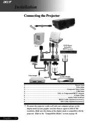
... computer, please set the display mode of the display mode is compatible with the projector. Refer to the "Compatibility Modes" section on page 34. Installation Connecting the Projector 1 USB RGB DVI RS232 8 4 29 DVD Player, Settop Box, HDTV receiver Video Output 7 3 6 5 S-Video Output English ... 10 1...Power Cord 2...VGA Cable 3 Composite Video...
... computer, please set the display mode of the display mode is compatible with the projector. Refer to the "Compatibility Modes" section on page 34. Installation Connecting the Projector 1 USB RGB DVI RS232 8 4 29 DVD Player, Settop Box, HDTV receiver Video Output 7 3 6 5 S-Video Output English ... 10 1...Power Cord 2...VGA Cable 3 Composite Video...
PD115 User's Guide EN
Page 11
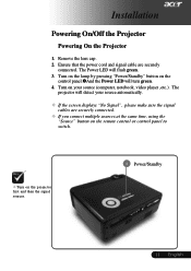
... ,etc.). Turn on the control panel.nAnd the Power LED will turn green. 4. English Ensure that the power cord and signal cable are securely connected. ™ If you connect multiple sources at the same time, using the "Source" button on the remote control or control panel to switch. ™ Turn on the... lamp by pressing "Power/Standby" button on your source automatically. ™ If the screen displays "No Signal", please make sure the signal cables are securely connected. Installation Powering On/Off the Projector Powering On the Projector 1.
... ,etc.). Turn on the control panel.nAnd the Power LED will turn green. 4. English Ensure that the power cord and signal cable are securely connected. ™ If you connect multiple sources at the same time, using the "Source" button on the remote control or control panel to switch. ™ Turn on the... lamp by pressing "Power/Standby" button on your source automatically. ™ If the screen displays "No Signal", please make sure the signal cables are securely connected. Installation Powering On/Off the Projector Powering On the Projector 1.

PD115 User's Guide EN
Page 16
... Button 4 Aim the remote at the viewing screen, press and hold this button to page down. This function is only available when the projector is connected to a computer via an USB cable. Source 4 Press "Source" to pause the screen image. User Controls English ... 16 Using the Remote Control Power 4 Refer to... Keys 4 Use your selection. Page Up (Computer mode only) 4 Use this button to the input source. This function is only available when the projector is connected to launch the on pages 11-12.
... Button 4 Aim the remote at the viewing screen, press and hold this button to page down. This function is only available when the projector is connected to a computer via an USB cable. Source 4 Press "Source" to pause the screen image. User Controls English ... 16 Using the Remote Control Power 4 Refer to... Keys 4 Use your selection. Page Up (Computer mode only) 4 Use this button to the input source. This function is only available when the projector is connected to launch the on pages 11-12.

PD115 User's Guide EN
Page 27
.... 2. Press and hold "Menu/Enter" button then press " " button. 5. English Please make sure the USB cable has been plugged and connected to your PC to their desired image. Before the download starts, the projector must enter "Download Mode" first. Please follow the instruction below to... the factory default settings. 27 ... Make sure all menus to enter "Download Mode". 1. User Controls Management (Computer / Video Mode) Acer My Start-up Screen is blinking. 4. Reset Press the button after choosing "Yes" to return the display parameters on again, release both buttons, ...
.... 2. Press and hold "Menu/Enter" button then press " " button. 5. English Please make sure the USB cable has been plugged and connected to your PC to their desired image. Before the download starts, the projector must enter "Download Mode" first. Please follow the instruction below to... the factory default settings. 27 ... Make sure all menus to enter "Download Mode". 1. User Controls Management (Computer / Video Mode) Acer My Start-up Screen is blinking. 4. Reset Press the button after choosing "Yes" to return the display parameters on again, release both buttons, ...
PD115 User's Guide EN
Page 28
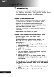
... than or equal to reset the resolution. Verify that your display resolution setting is switched on screen. 4 Ensure all the cables and power connections are correctly and securely connected as described in the Main group. 2. If the projector is not enabled. Refer to 1024 x 768 resolution. Please refer to the following steps...
... than or equal to reset the resolution. Verify that your display resolution setting is switched on screen. 4 Ensure all the cables and power connections are correctly and securely connected as described in the Main group. 2. If the projector is not enabled. Refer to 1024 x 768 resolution. Please refer to the following steps...


