
User Manual
Page 16
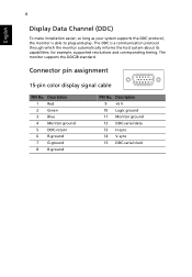
...DDC is able to plug-and-play. for example, supported resolutions and corresponding timing. Description 9 +5 V 10 Logic ground 11 Monitor ground 12 DDC-serial data 13 H-sync 14 V-sync 15 DDC-serial clock Description 1 Red 2 Green 3 Blue 4 Monitor ground 5 DDC-return 6 R-ground 7 G-ground 8 ...B-ground PIN No. Connector pin assignment 15-pin color display signal cable 1 5 6 10 11 15 PIN No. The monitor supports the DDC2B standard. 4 English Display Data Channel (DDC) ...
...DDC is able to plug-and-play. for example, supported resolutions and corresponding timing. Description 9 +5 V 10 Logic ground 11 Monitor ground 12 DDC-serial data 13 H-sync 14 V-sync 15 DDC-serial clock Description 1 Red 2 Green 3 Blue 4 Monitor ground 5 DDC-return 6 R-ground 7 G-ground 8 ...B-ground PIN No. Connector pin assignment 15-pin color display signal cable 1 5 6 10 11 15 PIN No. The monitor supports the DDC2B standard. 4 English Display Data Channel (DDC) ...
User Manual
Page 26
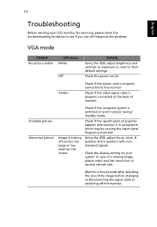
... missing, off the monitor. Image is in power saving/ standby mode. Using the OSD, adjust focus, clock, Hposition and V-position with nonstandard signals. Check the power switch. 14 English Troubleshooting Before sending your system. Check if the specification of a missing image, please select another resolution or vertical refresh rate. Unstable picture Abnormal...
... missing, off the monitor. Image is in power saving/ standby mode. Using the OSD, adjust focus, clock, Hposition and V-position with nonstandard signals. Check the power switch. 14 English Troubleshooting Before sending your system. Check if the specification of a missing image, please select another resolution or vertical refresh rate. Unstable picture Abnormal...


