Quick Start Guide
Page 1
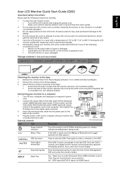
English Acer LCD Monitor Quick Start Guide (QSG) Important safety instructions Please read the following circumstances occur: • Monitor-to-PC signal cable is frayed or damaged. • Liquid spills onto the LCD monitor or the monitor is exposed to rain. • The ...• Secure the base to select between the OSD options. Press the Empowering Key to exit the OSD. Then tighten the thumbscrews on the signal cable connector. 3 Insert the monitor power cable into a nearby electrical outlet. Exposing the monitor to rain, moisture or sunlight can severely damage it...
English Acer LCD Monitor Quick Start Guide (QSG) Important safety instructions Please read the following circumstances occur: • Monitor-to-PC signal cable is frayed or damaged. • Liquid spills onto the LCD monitor or the monitor is exposed to rain. • The ...• Secure the base to select between the OSD options. Press the Empowering Key to exit the OSD. Then tighten the thumbscrews on the signal cable connector. 3 Insert the monitor power cable into a nearby electrical outlet. Exposing the monitor to rain, moisture or sunlight can severely damage it...
User Manual
Page 11
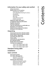
... device (for selected models) 5 Display Data Channel (DDC) 5 Connector pin assignment 5 15-pin color display signal cable 5 24-pin color display signal cable 6 19-pin color display signal cable* 6 Standard timing table 7 Installation 8 Users controls 9 Front panel controls 9 Acer eColor Management 10 Operation instructions 10 Features and benefits 10 Adjusting the OSD settings 11...
... device (for selected models) 5 Display Data Channel (DDC) 5 Connector pin assignment 5 15-pin color display signal cable 5 24-pin color display signal cable 6 19-pin color display signal cable* 6 Standard timing table 7 Installation 8 Users controls 9 Front panel controls 9 Acer eColor Management 10 Operation instructions 10 Features and benefits 10 Adjusting the OSD settings 11...
User Manual
Page 15
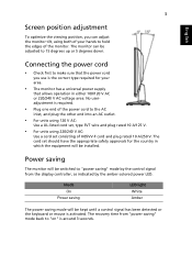
... power cord • Check first to make sure that allows operation in which the equipment will be switched to "power saving" mode by the control signal from "power saving" mode back to "on" is the correct type required for your hands to hold the edges of H05VV-F cord and plug rated..., as indicated by the amber-colored power LED. Mode On Power saving LED light White Amber The power saving mode will be kept until a control signal has been detected or the keyboard or mouse is required. • Plug one end of the power cord to the AC inlet, and plug the...
... power cord • Check first to make sure that allows operation in which the equipment will be switched to "power saving" mode by the control signal from "power saving" mode back to "on" is the correct type required for your hands to hold the edges of H05VV-F cord and plug rated..., as indicated by the amber-colored power LED. Mode On Power saving LED light White Amber The power saving mode will be kept until a control signal has been detected or the keyboard or mouse is required. • Plug one end of the power cord to the AC inlet, and plug the...
User Manual
Page 16
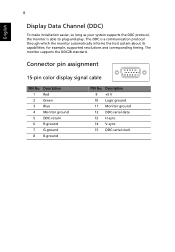
... protocol, the monitor is a communication protocol through which the monitor automatically informs the host system about its capabilities; Connector pin assignment 15-pin color display signal cable 1 5 6 10 11 15 PIN No. The DDC is able to plug-and-play. Description 1 Red 2 Green 3 Blue 4 Monitor ground 5 DDC-return 6 R-ground 7 G-ground 8 B-ground...
... protocol, the monitor is a communication protocol through which the monitor automatically informs the host system about its capabilities; Connector pin assignment 15-pin color display signal cable 1 5 6 10 11 15 PIN No. The DDC is able to plug-and-play. Description 1 Red 2 Green 3 Blue 4 Monitor ground 5 DDC-return 6 R-ground 7 G-ground 8 B-ground...

User Manual
Page 17
... TMDS data 0+ 19 TMDS data 0/5 shield 20 NC 21 NC 22 TMDS clock shield 23 TMDS clock+ 24 DDC TMDS clock- 19-pin color display signal cable* 1917151311 9 7 5 3 1 1816141210 8 6 4 2 PIN No. Description 2 TMDS Data2 Shield 4 TMDS Data1+ 6 TMDS Data1- 8 TMDS Data0 Shield 10 TMDS Clock+ 12 ... NC 6 DDC clock 7 DDC data 8 NC 9 TMDS data 1- 10 TMDS data 1+ 11 TMDS data 1/3 shield 12 NC PIN No. 5 24-pin color display signal cable English PIN No. Description 1 TMDS Data2+ 3 TMDS Data2- 5 TMDS Data1 Shield 7 TMDS Data0+ 9 TMDS Data0- 11 TMDS Clock Shield 13 CEC 15 SCL...
... TMDS data 0+ 19 TMDS data 0/5 shield 20 NC 21 NC 22 TMDS clock shield 23 TMDS clock+ 24 DDC TMDS clock- 19-pin color display signal cable* 1917151311 9 7 5 3 1 1816141210 8 6 4 2 PIN No. Description 2 TMDS Data2 Shield 4 TMDS Data1+ 6 TMDS Data1- 8 TMDS Data0 Shield 10 TMDS Clock+ 12 ... NC 6 DDC clock 7 DDC data 8 NC 9 TMDS data 1- 10 TMDS data 1+ 11 TMDS data 1/3 shield 12 NC PIN No. 5 24-pin color display signal cable English PIN No. Description 1 TMDS Data2+ 3 TMDS Data2- 5 TMDS Data1 Shield 7 TMDS Data0+ 9 TMDS Data0- 11 TMDS Clock Shield 13 CEC 15 SCL...
User Manual
Page 26
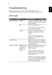
... at the back of a missing image, please select another resolution or vertical refresh rate. In case of monitor. Check if the video signal cable is properly connected to see if you can self-diagnose the problem. Unstable picture Abnormal picture Check if the computer system is missing,...below to the monitor. Image is switched on and in compliance which may be causing the input signal frequency mismatch. Check if the specification of the image before changing or disconnecting the signal cable or switching off -center, too large or too small on your LCD monitor for a ...
... at the back of a missing image, please select another resolution or vertical refresh rate. In case of monitor. Check if the video signal cable is properly connected to see if you can self-diagnose the problem. Unstable picture Abnormal picture Check if the computer system is missing,...below to the monitor. Image is switched on and in compliance which may be causing the input signal frequency mismatch. Check if the specification of the image before changing or disconnecting the signal cable or switching off -center, too large or too small on your LCD monitor for a ...
User Manual
Page 27
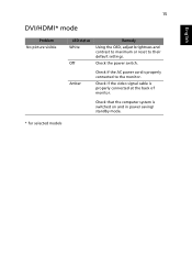
Check if the video signal cable is switched on and in power saving/ standby mode. * for selected models Check that the computer system is properly connected at the back of monitor. 15 English DVI/HDMI* mode Problem No picture visible LED status White Off Remedy Using the OSD, adjust brightness and contrast to maximum or reset to the monitor. Amber Check if the AC power cord is properly connected to their default settings. Check the power switch.
Check if the video signal cable is switched on and in power saving/ standby mode. * for selected models Check that the computer system is properly connected at the back of monitor. 15 English DVI/HDMI* mode Problem No picture visible LED status White Off Remedy Using the OSD, adjust brightness and contrast to maximum or reset to the monitor. Amber Check if the AC power cord is properly connected to their default settings. Check the power switch.


