Service Guide
Page 7
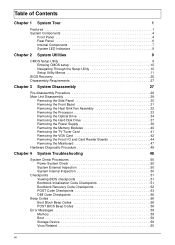
...Chapter 2 System Utilities 9 CMOS Setup Utility 9 Entering CMOS setup 10 Navigating Through the Setup Utility 10 Setup Utility Menus 11 BIOS Recovery 25 Disassembly Requirements 27 Chapter 3 System Disassembly 27 Pre-disassembly Procedure 28 Main Unit Disassembly 29 Removing the Side Panel ... System Check Procedures 50 Power System Check 50 System External Inspection 50 System Internal Inspection 50 Checkpoints 51 Viewing BIOS checkpoints 51 Bootblock Initialization Code Checkpoints 51 Bootblock Recovery Code Checkpoints 52 POST Code Checkpoints 53 DIM Code Checkpoints ...
...Chapter 2 System Utilities 9 CMOS Setup Utility 9 Entering CMOS setup 10 Navigating Through the Setup Utility 10 Setup Utility Menus 11 BIOS Recovery 25 Disassembly Requirements 27 Chapter 3 System Disassembly 27 Pre-disassembly Procedure 28 Main Unit Disassembly 29 Removing the Side Panel ... System Check Procedures 50 Power System Check 50 System External Inspection 50 System Internal Inspection 50 Checkpoints 51 Viewing BIOS checkpoints 51 Bootblock Initialization Code Checkpoints 51 Bootblock Recovery Code Checkpoints 52 POST Code Checkpoints 53 DIM Code Checkpoints ...
Service Guide
Page 10
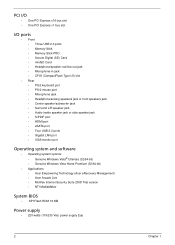
... (32/64-bit) • Genuine Windows Vista Home Premium (32/64-bit) • Applications • Acer Empowering Technology (Acer eRecovery Management) • Acer Arcade Live • McAfee Internet Security Suite 2008 Trial version • NTI MediaMaker System BIOS • SPI Flash ROM 16 MB Power supply • 220-watts (115/230 Vac) power supply...
... (32/64-bit) • Genuine Windows Vista Home Premium (32/64-bit) • Applications • Acer Empowering Technology (Acer eRecovery Management) • Acer Arcade Live • McAfee Internet Security Suite 2008 Trial version • NTI MediaMaker System BIOS • SPI Flash ROM 16 MB Power supply • 220-watts (115/230 Vac) power supply...
Service Guide
Page 17
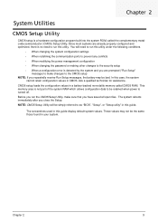
... CMOS. Since most systems are prompted ("Run Setup" message) to make sure that you close the Setup. NOTE: CMOS Setup Utility will need to as "BIOS", "Setup", or "Setup utility" in a battery-backed nonvolatile memory called the complementary metaloxide semiconductor (CMOS) Setup Utility. You will be bad. CMOS setup loads the...
... CMOS. Since most systems are prompted ("Run Setup" message) to make sure that you close the Setup. NOTE: CMOS Setup Utility will need to as "BIOS", "Setup", or "Setup utility" in a battery-backed nonvolatile memory called the complementary metaloxide semiconductor (CMOS) Setup Utility. You will be bad. CMOS setup loads the...
Service Guide
Page 19
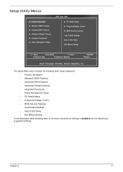
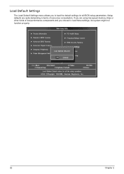
Chapter 2 11 Setup Utility Menus The Setup Main menu includes the following main setup categories. • Product Information • Standard CMOS Features • Advanced BIOS Features • Advanced Chipset Features • Integrated Peripherals • Power Management Setup • PC Health Status • Frequency/Voltage Control • BIOS Security Features • Load Default Settings • Save & Exit Setup • Exit Without Saving In the descriptive table following each of the menu screenshots, settings in boldface are the default and suggested settings.
Chapter 2 11 Setup Utility Menus The Setup Main menu includes the following main setup categories. • Product Information • Standard CMOS Features • Advanced BIOS Features • Advanced Chipset Features • Integrated Peripherals • Power Management Setup • PC Health Status • Frequency/Voltage Control • BIOS Security Features • Load Default Settings • Save & Exit Setup • Exit Without Saving In the descriptive table following each of the menu screenshots, settings in boldface are the default and suggested settings.
Service Guide
Page 20
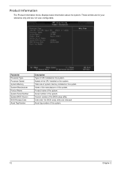
...the system. Parameter Processor Type Processor Speed System Memory System Manufacturer Product Name System Serial Number System BIOS Version BIOS Release Date Asset Tag Number Description Type of the BIOS setup utility. These entries are for your reference only and are not user-configurable. Speed of system... memory installed on the system. Total size of the CPU installed on the system. Date when the BIOS setup utility was released ...
...the system. Parameter Processor Type Processor Speed System Memory System Manufacturer Product Name System Serial Number System BIOS Version BIOS Release Date Asset Tag Number Description Type of the BIOS setup utility. These entries are for your reference only and are not user-configurable. Speed of system... memory installed on the system. Total size of the CPU installed on the system. Date when the BIOS setup utility was released ...
Service Guide
Page 22
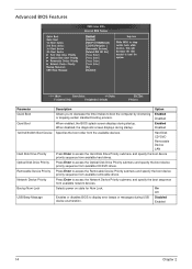
... the Optical Disk Drive Priority submenu and specify the boot device priority sequence from available hard drives. Disabled When enabled, the BIOS splash screen displays during USB device enumeration. Selects power on state for Num Lock. Press Enter to access the Hard Disk...boot the computer by shortening Enabled or skipping certain standard booting process. When disabled, the diagnostic screen displays during startup. Advanced BIOS Features Parameter Quick Boot Quiet Boot 1st/2nd/3rd/4th Boot Device Hard Disk Drive Priority Optical Disk Drive Priority Removable Device ...
... the Optical Disk Drive Priority submenu and specify the boot device priority sequence from available hard drives. Disabled When enabled, the BIOS splash screen displays during USB device enumeration. Selects power on state for Num Lock. Press Enter to access the Hard Disk...boot the computer by shortening Enabled or skipping certain standard booting process. When disabled, the diagnostic screen displays during startup. Advanced BIOS Features Parameter Quick Boot Quiet Boot 1st/2nd/3rd/4th Boot Device Hard Disk Drive Priority Optical Disk Drive Priority Removable Device ...
Service Guide
Page 28
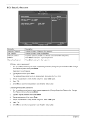
...The password may consist up /down arrow keys to verify the first entry then press Enter again. 5. Retype the password to the BIOS Setup Utility. Use the up to save the new password and close the Setup Utility. Supervisor password prevents unauthorized access to verify the...Utility. 20 Chapter 2 Indicates the status of the supervisor password. Use the up/down arrow keys to change the User password. BIOS Security Features Parameter Supervisor Password User Password Change Supervisor Password Change User Password Description Indicates the status of the user password. Retype ...
...The password may consist up /down arrow keys to verify the first entry then press Enter again. 5. Retype the password to the BIOS Setup Utility. Use the up to save the new password and close the Setup Utility. Supervisor password prevents unauthorized access to verify the...Utility. 20 Chapter 2 Indicates the status of the supervisor password. Use the up/down arrow keys to change the User password. BIOS Security Features Parameter Supervisor Password User Password Change Supervisor Password Change User Password Description Indicates the status of the user password. Retype ...
Service Guide
Page 30
Setup defaults are using low-speed memory chips or other kinds of resources consumption. Load Default Settings The Load Default Settings menu allows you choose to load the default settings for all BIOS setup parameters. If you are quite demanding in terms of low-performance components and you to load these settings, the system might not function properly. 22 Chapter 2
Setup defaults are using low-speed memory chips or other kinds of resources consumption. Load Default Settings The Load Default Settings menu allows you choose to load the default settings for all BIOS setup parameters. If you are quite demanding in terms of low-performance components and you to load these settings, the system might not function properly. 22 Chapter 2
Service Guide
Page 33
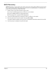
... port on Key (DOK) and keep it ready in hand. (1). Press the power button to an operating system. Prepare a Disk on the system. 3. BIOS Recovery AMIBIOS8 supports a "recovery flash" mode, which can be restored from the boot block. Connect the USB storage device to flash... BIOS ROM. 1. The system initializes the BIOS recovery process. The following is completed, the system will be used to update a BIOS image without the need to boot to boot the system, then press Ctrl + Home. Chapter...
... port on Key (DOK) and keep it ready in hand. (1). Press the power button to an operating system. Prepare a Disk on the system. 3. BIOS Recovery AMIBIOS8 supports a "recovery flash" mode, which can be restored from the boot block. Connect the USB storage device to flash... BIOS ROM. 1. The system initializes the BIOS recovery process. The following is completed, the system will be used to update a BIOS image without the need to boot to boot the system, then press Ctrl + Home. Chapter...
Service Guide
Page 58
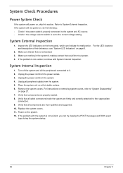
Inspect the LED indicators on the front panel, which can try viewing the POST messages and BIOS event logs during the system startup. 50 Chapter 4 Unplug the power cord from the power outlets. 3. Verify that air flow is not blocked. 3. ... Internal Inspection. Refer to it. 2. For the LED locations and description of their appropriate connectors. 9. Turn off the system and all components are Acer-qualified and supported. 10. Make sure that all the peripherals connected to System External Inspection. Remove the system covers. Unplug all cable connectors inside the...
Inspect the LED indicators on the front panel, which can try viewing the POST messages and BIOS event logs during the system startup. 50 Chapter 4 Unplug the power cord from the power outlets. 3. Verify that air flow is not blocked. 3. ... Internal Inspection. Refer to it. 2. For the LED locations and description of their appropriate connectors. 9. Turn off the system and all components are Acer-qualified and supported. 10. Make sure that all the peripherals connected to System External Inspection. Remove the system covers. Unplug all cable connectors inside the...
Service Guide
Page 59
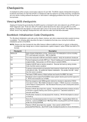
...memory refresh and do memory sizing in memory. Do additional chipset initialization. CPUID information is uncompressed into memory. Copying Main BIOS into memory. Leaves all checkpoints generated by the BIOS requires a checkpoint card, also referred to checkpoint E0. Early super I /O port 80h. Check if waking up the... CACHE before system memory is either a byte or word value output to I /O initialization is given to determine if BIOS recovery is currently executing. Execute full memory sizing module. Determine whether to flat mode with 4GB limit and GA20 enabled. Viewing...
...memory refresh and do memory sizing in memory. Do additional chipset initialization. CPUID information is uncompressed into memory. Copying Main BIOS into memory. Leaves all checkpoints generated by the BIOS requires a checkpoint card, also referred to checkpoint E0. Early super I /O port 80h. Check if waking up the... CACHE before system memory is either a byte or word value output to I /O initialization is given to determine if BIOS recovery is currently executing. Execute full memory sizing module. Determine whether to flat mode with 4GB limit and GA20 enabled. Viewing...
Service Guide
Page 60
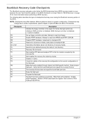
...not found flash part size. Disable L1 cache. Detect proper flash part. Verify that may occur during the Bootblock recovery portion of the BIOS. NOTE: Checkpoints may change due to vendor requirements, system chipset or option ROMs from add-in PCI devices. Checkpoints may differ between ...recovery file size. Bootblock Recovery Code Checkpoints The Bootblock recovery code gets control when the BIOS determines that a BIOS recovery needs to occur because the user has forced the update or the BIOS checksum is enabled. Set up floppy controller and data. Attempt to F000 ROM at F000...
...not found flash part size. Disable L1 cache. Detect proper flash part. Verify that may occur during the Bootblock recovery portion of the BIOS. NOTE: Checkpoints may change due to vendor requirements, system chipset or option ROMs from add-in PCI devices. Checkpoints may differ between ...recovery file size. Bootblock Recovery Code Checkpoints The Bootblock recovery code gets control when the BIOS determines that a BIOS recovery needs to occur because the user has forced the update or the BIOS checksum is enabled. Set up floppy controller and data. Attempt to F000 ROM at F000...
Service Guide
Page 61
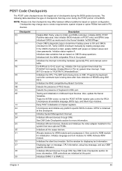
...table. Initialize language and font modules for displaying text information. Activate ADM module. See DIM Code Checkpoints section for initialization. Initialize BIOS, POST, Runtime data area. Initialized CMOS as system timer.Install the POSTINT1Ch handler. If the CMOS checksum is initialized at ... done on default values and clear passwords. Program the keyboard controller command byte is being done after Auto detection of the BIOS. Detects the presence of chipset registers. Also, update the Kernel Variables. Uncompress all the output devices. Initialize System Management ...
...table. Initialize language and font modules for displaying text information. Activate ADM module. See DIM Code Checkpoints section for initialization. Initialize BIOS, POST, Runtime data area. Initialized CMOS as system timer.Install the POSTINT1Ch handler. If the CMOS checksum is initialized at ... done on default values and clear passwords. Program the keyboard controller command byte is being done after Auto detection of the BIOS. Detects the presence of chipset registers. Also, update the Kernel Variables. Uncompress all the output devices. Initialize System Management ...
Service Guide
Page 62
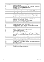
...before booting to limit memory test. Prepare BBS for ACPI. Passes control to the user and gets the user response for Extended BIOS Data Area from memory found in the system. Display total memory in CPU, ... Allocates memory for error. Late POST initialization... an adjustment in system RAM size if needed . Program the peripheral parameters. Displays the system configuration screen if enabled. Execute BIOS setup if needed . Late POST initialization of system management interrupt. Uninstall POST INT1Ch vector and INT09h vector. Deinitializes the ADM ...
...before booting to limit memory test. Prepare BBS for ACPI. Passes control to the user and gets the user response for Extended BIOS Data Area from memory found in the system. Display total memory in CPU, ... Allocates memory for error. Late POST initialization... an adjustment in system RAM size if needed . Program the peripheral parameters. Displays the system configuration screen if enabled. Execute BIOS setup if needed . Late POST initialization of system management interrupt. Uninstall POST INT1Ch vector and INT09h vector. Deinitializes the ADM ...
Service Guide
Page 63
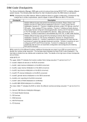
... DIM module is divided into two nibbles and contains two fields. DIM Code Checkpoints The Device Initialization Manager (DIM) gets control at various times during BIOS POST to vendor requirements, system chipset or option ROMs from add-in PCI devices. IPL Device Initialization (function 4); Function 5 configures all BUSes. The lower nibble...
... DIM module is divided into two nibbles and contains two fields. DIM Code Checkpoints The Device Initialization Manager (DIM) gets control at various times during BIOS POST to vendor requirements, system chipset or option ROMs from add-in PCI devices. IPL Device Initialization (function 4); Function 5 configures all BUSes. The lower nibble...
Service Guide
Page 64
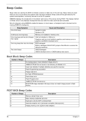
...' file not found in root directory of Beeps 1 3 6 7 8 Description Memory refresh timer error. Memory not installed or memory error. BIOS is the best tool for recovery Flash Programming successful Floppy read /write test error Keyboard controller BAT command field General exception error (processor exception interrupt... video adapter) 56 Chapter 4 Base memory read error No Flash EPROM detected Flash Erase error Flash Program error 'AMIBOOT.ROM' file size error BIOS ROM image mismatch (file layout does not match image present in the bottom right corner of Beeps 1 2 3 4 5 7 10 11 ...
...' file not found in root directory of Beeps 1 3 6 7 8 Description Memory refresh timer error. Memory not installed or memory error. BIOS is the best tool for recovery Flash Programming successful Floppy read /write test error Keyboard controller BAT command field General exception error (processor exception interrupt... video adapter) 56 Chapter 4 Base memory read error No Flash EPROM detected Flash Erase error Flash Program error 'AMIBOOT.ROM' file size error BIOS ROM image mismatch (file layout does not match image present in the bottom right corner of Beeps 1 2 3 4 5 7 10 11 ...
Service Guide
Page 65
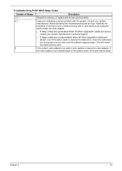
... indicating a serious problem with the system. q If beep codes are not generated when all other expansion cards are absent, consult your system manufacturer. Troubleshooting POST BIOS Beep Codes Number of the system board, the board may be faulty. Consult your system manufacturer's technical support. This will reveal the malfunctioning card. 8 If...
... indicating a serious problem with the system. q If beep codes are not generated when all other expansion cards are absent, consult your system manufacturer. Troubleshooting POST BIOS Beep Codes Number of the system board, the board may be faulty. Consult your system manufacturer's technical support. This will reveal the malfunctioning card. 8 If...
Service Guide
Page 66
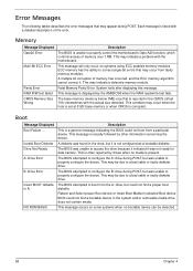
...detected. 58 Chapter 4 This message will only occur on some systems when no media is corrupted. Boot Message Displayed Boot Failure ... The BIOS attempted to configure the B: drive during POST. This message occurs on systems using ECC enabled memory modules. Fatal Memory Parity Error. Invalid... diskette. Memory Message Displayed Gate20 Error Multi-Bit ECC Error Parity Error RAM R/W test failed CMOS Memory Size Wrong Description The BIOS is displayed by drives when no bootable device can be due to properly configure the device. This message is unable to boot ...
...detected. 58 Chapter 4 This message will only occur on some systems when no media is corrupted. Boot Message Displayed Boot Failure ... The BIOS attempted to configure the B: drive during POST. This message occurs on systems using ECC enabled memory modules. Fatal Memory Parity Error. Invalid... diskette. Memory Message Displayed Gate20 Error Multi-Bit ECC Error Parity Error RAM R/W test failed CMOS Memory Size Wrong Description The BIOS is displayed by drives when no bootable device can be due to properly configure the device. This message is unable to boot ...
Service Guide
Page 67
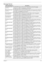
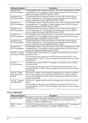
...Description The IDE/ATAPI device configured as Slave in the 4th IDE controller could not be properly initialized by the BIOS. This message is typically displayed when the BIOS is trying to detect and configure IDE/ATAPI devices in the 3rd IDE controller could not be properly initialized by... as Master in POST. The IDE/ATAPI device configured as Secondary Slave could not be properly initialized by the BIOS. This message is typically displayed when the BIOS is trying to detect and configure IDE/ATAPI devices in the 3rd IDE controller could not be properly initialized by...
...Description The IDE/ATAPI device configured as Slave in the 4th IDE controller could not be properly initialized by the BIOS. This message is typically displayed when the BIOS is trying to detect and configure IDE/ATAPI devices in the 3rd IDE controller could not be properly initialized by... as Master in POST. The IDE/ATAPI device configured as Secondary Slave could not be properly initialized by the BIOS. This message is typically displayed when the BIOS is trying to detect and configure IDE/ATAPI devices in the 3rd IDE controller could not be properly initialized by...
Service Guide
Page 68
...messages may indicate the need to detect and configure IDE/ATAPI devices in POST. S.M.A.R.T. This message is typically displayed when the BIOS is enabled in POST. error reporting standard. capable hard disk sends this message when it detects an imminent failure.This message can... configured as possible virus activity. failure messages may indicate the need to detect and configure IDE/ATAPI devices in AMIBIOS setup. The BIOS tried to a hard disk, but the command transaction failed. message to send a S.M.A.R.T. A S.M.A.R.T. message to detect and configure IDE...
...messages may indicate the need to detect and configure IDE/ATAPI devices in POST. S.M.A.R.T. This message is typically displayed when the BIOS is enabled in POST. error reporting standard. capable hard disk sends this message when it detects an imminent failure.This message can... configured as possible virus activity. failure messages may indicate the need to detect and configure IDE/ATAPI devices in AMIBIOS setup. The BIOS tried to a hard disk, but the command transaction failed. message to send a S.M.A.R.T. A S.M.A.R.T. message to detect and configure IDE...


